US461002A - Lubricating device - Google Patents
Lubricating device Download PDFInfo
- Publication number
- US461002A US461002A US461002DA US461002A US 461002 A US461002 A US 461002A US 461002D A US461002D A US 461002DA US 461002 A US461002 A US 461002A
- Authority
- US
- United States
- Prior art keywords
- oil
- steam
- plug
- channel
- perforations
- Prior art date
- Legal status (The legal status is an assumption and is not a legal conclusion. Google has not performed a legal analysis and makes no representation as to the accuracy of the status listed.)
- Expired - Lifetime
Links
- 230000001050 lubricating effect Effects 0.000 title description 3
- 230000037431 insertion Effects 0.000 description 2
- 238000003780 insertion Methods 0.000 description 2
- 238000004140 cleaning Methods 0.000 description 1
- 238000010276 construction Methods 0.000 description 1
- 238000007599 discharging Methods 0.000 description 1
- 230000000694 effects Effects 0.000 description 1
- 230000001788 irregular Effects 0.000 description 1
- 230000008439 repair process Effects 0.000 description 1
- 230000000717 retained effect Effects 0.000 description 1
- 230000008016 vaporization Effects 0.000 description 1
- 239000002699 waste material Substances 0.000 description 1
Images
Classifications
-
- F—MECHANICAL ENGINEERING; LIGHTING; HEATING; WEAPONS; BLASTING
- F16—ENGINEERING ELEMENTS AND UNITS; GENERAL MEASURES FOR PRODUCING AND MAINTAINING EFFECTIVE FUNCTIONING OF MACHINES OR INSTALLATIONS; THERMAL INSULATION IN GENERAL
- F16N—LUBRICATING
- F16N7/00—Arrangements for supplying oil or unspecified lubricant from a stationary reservoir or the equivalent in or on the machine or member to be lubricated
- F16N7/30—Arrangements for supplying oil or unspecified lubricant from a stationary reservoir or the equivalent in or on the machine or member to be lubricated the oil being fed or carried along by another fluid
Definitions
- Our invention relates to lubricators, and more particularly to those adapted for lubricating steam-cylinders, and has for its object to atomize the oil and distribute it to the cylinder equally over all its parts, wherebya superior effect is accomplished and the oil is used economically.
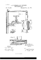
- Figure 1 is a vertical sectional view of our improved device and so much of a steamengine as is necessary to show its application and use.
- Fig. 2 is a detail perspective view of one portion of it, and
- Fig. 3 is a vertical sectional view of another form.
- 1 indicates a cock, which is provided with the usual valve 2, which regulates the flow of oil from the reservoir 3, to which the cock is connected in any convenient manner.
- the cock is provided at the exit or discharge with an extension 4, which leads into or con- 11 ects with the steam-pipe 5, leading to the cylinder.
- the extension is provided with two channels or passages 6 and 7, one of which 6 is preferably made round and is for the passage of the steam from the steam-pipe into the interior of the other channel near the valve 2.
- the other channel 7 is a continuation of the channel through the cock and is of irregular cross-section and is provided with an inclined surface 8, leading from the valve 2 or inlet into the channel 7, and is located directly under the inlet of the channel 6.
- the foot of the incline is placed a plug 9, the inner end of which is made hollow and provided with small perforations upon its upper surface and projects into the channel 7, which at this point is preferably made perpendicular.
- a thin plate 10, provided with small perforations, is placed at or near the end of the hollow portion of the plug, which will assist in breaking up or vaporizing the oil, as will be hereinafter more fully explained.
- From the end of the plug the channel 7 extends in a straight line to the inner end of the extension and terminates ina downwardly-extending pipe 11 in the steam-pipe. The lower end of this pipe is closed by a plug 12 and is provided with small perforations just above the plug.
- the extension can be made separate and be attached to the cock in any suitable manner, or it can be cast integral therewith, and the channels through it formed in the most convenient way, an enlarged oil-chamber 13 being formed above the inclined surface 8, and the opening 14 for the insertion of the plug 9 being preferably provided with screw-ch reads for the insertion or removal of the plug.
- the channel through the cock is opened by raising the valve 2, which will permit the passage of the oil from the reservoir, which maybe connected with the steampipe by a small pipe 15, which will force the oil through the cock.
- the oil enters the extension it is cold and sluggish and flows down the inclined surface S; but it hardly starts down the incline until it passes under the inlet or opening of the channel ,6, which is curved, so as to cause the steam to strike the incline almost perpendicularly.
- the hot steam entering through the channel 6 heats the oil to nearly steam heat and vaporizes it within the oil-chamber 13.
- the plug 9 provided with screw-threads for securing it in the extensions and having a head or shoulders for the reception of awrench, it could be made without them and any other ordinary means adapted for securing it in the extension, and the hollow in the inner end may be dispensed with and the perforations be passed entirely through it, or if the hollow is retained the perforations might be extended entirely around the plug, as the object of the perforations is to break up the oil, and they can be arranged in any manner which will best accomplish that object without obstructing the passage of the oil, and the plate 10 may be provided with shoulders 17 and be fitted intoa slot 18, out near the end of the plug, so that it may be easily removed for cleaning or for repairs.
- FIG. 3 Another form of our atomizer is shown in Fig. 3, and consists of aplug 19, which is connected with the oil-reservoir in any suitable manner, and is provided with small perforations 20 near its inner end.
- a valve-seat 21 is formed, upon which rests a valve 22, the stem of which passes beyond the perforations 20, and is provided with a head or piston 23, which fits the chamber or bore of the tube at that point.
- the combination with a body provided with two passages, each communicating with the steam-supply pipe and one of them with the oil-supply, of a perforated plug across the oil-passage beyond the entrance of
Landscapes
- Engineering & Computer Science (AREA)
- General Engineering & Computer Science (AREA)
- Chemical & Material Sciences (AREA)
- Combustion & Propulsion (AREA)
- Oil, Petroleum & Natural Gas (AREA)
- Mechanical Engineering (AREA)
- Fats And Perfumes (AREA)
Description
(No Model.) I
J. E. TOTMAN & M. ERICKSEN.
LUBRIGATING DEVICE.
No. 461,002. Patented Oct. 13,1891.
A9 JZemesZT 2323mm marzzzzr e s @71/ W/T/VESSES. INVENTORS,
MW MM QM A UNITED STATES PATENT OFFICE.
JAMES E. TOTMAN AND MARTIN ERICKSEN, OF LA CROSSE, ISCONSIN.
LUBRICATING DEVICE.
SPECIFICATION forming part of Letters Patent No. 461,002, dated October 13, 1891.
Application filed April 4, 1891. Serial N0. 387,594. (No model.)
T 0 all whom it may concern:
Be it known that we, J AMES E. TOTMAN and MARTIN ERICKSEN, citizens of the United States, residingat La Crosse, in the county of La Orosse and State of I/Visconsin, have invented certain new and useful Improvements in Lubricating Devices; and we do declare the following to be a full, clear, and exact description of the invention, such as will enable others skilled in the art to which it appertains to make and usethe same, reference being had to the accompanying drawings, and to the figures of reference marked thereon, which form a part of this specification.
Our invention relates to lubricators, and more particularly to those adapted for lubricating steam-cylinders, and has for its object to atomize the oil and distribute it to the cylinder equally over all its parts, wherebya superior effect is accomplished and the oil is used economically.
To this end the invention consists in the improved construction and arrangements of parts, as will be hereinafter more particularly set forth.
In the accompanying drawings, in which the same reference numerals indicate similar parts, Figure 1 is a vertical sectional view of our improved device and so much of a steamengine as is necessary to show its application and use. Fig. 2 is a detail perspective view of one portion of it, and Fig. 3 is a vertical sectional view of another form.
Referring more particularly to the drawings, 1 indicates a cock, which is provided with the usual valve 2, which regulates the flow of oil from the reservoir 3, to which the cock is connected in any convenient manner. The cock is provided at the exit or discharge with an extension 4, which leads into or con- 11 ects with the steam-pipe 5, leading to the cylinder. The extension is provided with two channels or passages 6 and 7, one of which 6 is preferably made round and is for the passage of the steam from the steam-pipe into the interior of the other channel near the valve 2. The other channel 7 is a continuation of the channel through the cock and is of irregular cross-section and is provided with an inclined surface 8, leading from the valve 2 or inlet into the channel 7, and is located directly under the inlet of the channel 6. At
the foot of the incline is placed a plug 9, the inner end of which is made hollow and provided with small perforations upon its upper surface and projects into the channel 7, which at this point is preferably made perpendicular. A thin plate 10, provided with small perforations, is placed at or near the end of the hollow portion of the plug, which will assist in breaking up or vaporizing the oil, as will be hereinafter more fully explained. From the end of the plug the channel 7 extends in a straight line to the inner end of the extension and terminates ina downwardly-extending pipe 11 in the steam-pipe. The lower end of this pipe is closed by a plug 12 and is provided with small perforations just above the plug.
The extension can be made separate and be attached to the cock in any suitable manner, or it can be cast integral therewith, and the channels through it formed in the most convenient way, an enlarged oil-chamber 13 being formed above the inclined surface 8, and the opening 14 for the insertion of the plug 9 being preferably provided with screw-ch reads for the insertion or removal of the plug.
In operation the channel through the cock is opened by raising the valve 2, which will permit the passage of the oil from the reservoir, which maybe connected with the steampipe by a small pipe 15, which will force the oil through the cock. As the oil enters the extension it is cold and sluggish and flows down the inclined surface S; but it hardly starts down the incline until it passes under the inlet or opening of the channel ,6, which is curved, so as to cause the steam to strike the incline almost perpendicularly. The hot steam entering through the channel 6 heats the oil to nearly steam heat and vaporizes it within the oil-chamber 13. From here the oil and steam pass through the small perforations 16 into the interior of the plug 9, and from whence they pass through the perforated plate 10 into'the straight portion of the channel. In the passage through the perforations in the plug and the plate the oil is very considerably broken up and mixed with the steam, which also heats it to a great extent. From the channel 7 the steam and oil pass through the fine perforations in the end of the pipe or tube 11 out into the steam-pipe time the oil is completely broken up or atomized and is evenly distributed to every part to which the steam is admitted. In this manner we find that a very small quantity of oil -is needed, and that it is applied in such a manner that the most satisfactory results are obtained.
Although we have shown the plug 9 provided with screw-threads for securing it in the extensions and having a head or shoulders for the reception of awrench, it could be made without them and any other ordinary means adapted for securing it in the extension, and the hollow in the inner end may be dispensed with and the perforations be passed entirely through it, or if the hollow is retained the perforations might be extended entirely around the plug, as the object of the perforations is to break up the oil, and they can be arranged in any manner which will best accomplish that object without obstructing the passage of the oil, and the plate 10 may be provided with shoulders 17 and be fitted intoa slot 18, out near the end of the plug, so that it may be easily removed for cleaning or for repairs.
' Another form of our atomizer is shown in Fig. 3, and consists of aplug 19, which is connected with the oil-reservoir in any suitable manner, and is provided with small perforations 20 near its inner end. At any convenient point within the tube a valve-seat 21 is formed, upon which rests a valve 22, the stem of which passes beyond the perforations 20, and is provided with a head or piston 23, which fits the chamber or bore of the tube at that point. Now it is evident that when the engine is inoperation the pressure of the steam upon the head 23, which is of a larger area than the valve 22, will force the valve off its seat against the pressure ofthe oil from the reservoir and let the oil flow through the tube and be driven out through the perforations 20 and commingled with the steam that is passing to the engine. As soon as the steampressure is shut off, as in stopping the engine, the pressure of the oil upon the valve will force it upon its seat, and thus automatically shutoif the flow of oil and prevent any waste which would occur if it continued to flow after the steam had been shut off.
Having thus described our invention, we claim a 1. In an attachment for lubricators for steam-cylinders, the combination, with a body provided with an enlarged oil-conduit and having an inclined surface a portion of its length, of a perforated plug in the conduit beyond the inclined surface, and a steam-conduit leading from the steam-pipe and communicating with the oil-conduit opposite to and discharging upon the inclined surface, sub
stantially as described.
2. In an. attachment for lubricators for steam-cylinders, the combination, with a body having two channels, each communicating with the steam-supply pipe and one of them with the oil-supply, of a perforated plug across one of the channels, said channel being formed with an inclined surface, and an oil-chamber above the plug, substantially as described.
3. In an attachment for lubricators for steam-cylinders, the combination, with abody provided with a channel for the passage of the oil anda second passage for the entrance of steam thereto from the steam-pipe, of a plug in the passage, the inner end of which is hollow and provided with perforations, and a perforated plate in the end of the plug, substantially as described.
at. In an attachment for lubricators for steam-cylinders, the combination, with a body provided with two passages, each communicating with the steam-supply pipe and one of them with the oil-supply, of a perforated plug across the oil-passage beyond the entrance of
Publications (1)
| Publication Number | Publication Date |
|---|---|
| US461002A true US461002A (en) | 1891-10-13 |
Family
ID=2529875
Family Applications (1)
| Application Number | Title | Priority Date | Filing Date |
|---|---|---|---|
| US461002D Expired - Lifetime US461002A (en) | Lubricating device |
Country Status (1)
| Country | Link |
|---|---|
| US (1) | US461002A (en) |
-
0
- US US461002D patent/US461002A/en not_active Expired - Lifetime
Similar Documents
| Publication | Publication Date | Title |
|---|---|---|
| US909190A (en) | Hydrocarbon-burner. | |
| US339251A (en) | Lubricator | |
| US300619A (en) | cheistophee | |
| US187964A (en) | Improvement in lubricators | |
| US1116662A (en) | Lubricating device. | |
| US204672A (en) | Improvement in lubricators | |
| US1353081A (en) | Method of and means for feeding lubricant to steam-engines | |
| US312973A (en) | Lubricator | |
| US854553A (en) | Oil-burner. | |
| US611759A (en) | mccoy | |
| US1050690A (en) | Lubricator. | |
| US626166A (en) | Nohhis peters co | |
| US790461A (en) | Engine self-oiling mechanism. | |
| US387114A (en) | Oil-feeder | |
| US1102034A (en) | Atomizer. | |
| US294151A (en) | Lubricator | |
| US265180A (en) | Allen w | |
| US298011A (en) | Lubricator | |
| US298813A (en) | Luther b | |
| US1066048A (en) | Sight-feed lubricator. | |
| US1195695A (en) | lewis | |
| US377593A (en) | Lubricator | |
| US413295A (en) | Milton s | |
| US165901A (en) | Improvement in lubricators for steam-engines | |
| US154051A (en) | Improvement in lubricators |