US4609090A - Method and apparatus for moving and handling heavy objects - Google Patents
Method and apparatus for moving and handling heavy objects Download PDFInfo
- Publication number
- US4609090A US4609090A US06/441,933 US44193382A US4609090A US 4609090 A US4609090 A US 4609090A US 44193382 A US44193382 A US 44193382A US 4609090 A US4609090 A US 4609090A
- Authority
- US
- United States
- Prior art keywords
- workpiece
- ramp
- contour
- gravity
- center
- Prior art date
- Legal status (The legal status is an assumption and is not a legal conclusion. Google has not performed a legal analysis and makes no representation as to the accuracy of the status listed.)
- Expired - Fee Related
Links
- 238000000034 method Methods 0.000 title claims abstract description 15
- 238000005096 rolling process Methods 0.000 claims abstract description 29
- 230000005484 gravity Effects 0.000 claims abstract description 20
- 239000000463 material Substances 0.000 claims description 13
- 230000008878 coupling Effects 0.000 claims 2
- 238000010168 coupling process Methods 0.000 claims 2
- 238000005859 coupling reaction Methods 0.000 claims 2
- 230000001154 acute effect Effects 0.000 description 8
- 238000010586 diagram Methods 0.000 description 8
- 239000002783 friction material Substances 0.000 description 3
- 230000001788 irregular Effects 0.000 description 2
- 238000004519 manufacturing process Methods 0.000 description 2
- 101150044059 BEGAIN gene Proteins 0.000 description 1
- 238000012938 design process Methods 0.000 description 1
- 229920001971 elastomer Polymers 0.000 description 1
- 229920001084 poly(chloroprene) Polymers 0.000 description 1
- 230000000284 resting effect Effects 0.000 description 1
Images


Classifications
-
- B—PERFORMING OPERATIONS; TRANSPORTING
- B65—CONVEYING; PACKING; STORING; HANDLING THIN OR FILAMENTARY MATERIAL
- B65G—TRANSPORT OR STORAGE DEVICES, e.g. CONVEYORS FOR LOADING OR TIPPING, SHOP CONVEYOR SYSTEMS OR PNEUMATIC TUBE CONVEYORS
- B65G7/00—Devices for assisting manual moving or tilting heavy loads
- B65G7/02—Devices adapted to be interposed between loads and the ground or floor, e.g. crowbars with means for assisting conveyance of loads
- B65G7/08—Devices adapted to be interposed between loads and the ground or floor, e.g. crowbars with means for assisting conveyance of loads for tilting the loads
-
- B—PERFORMING OPERATIONS; TRANSPORTING
- B65—CONVEYING; PACKING; STORING; HANDLING THIN OR FILAMENTARY MATERIAL
- B65G—TRANSPORT OR STORAGE DEVICES, e.g. CONVEYORS FOR LOADING OR TIPPING, SHOP CONVEYOR SYSTEMS OR PNEUMATIC TUBE CONVEYORS
- B65G7/00—Devices for assisting manual moving or tilting heavy loads
- B65G7/02—Devices adapted to be interposed between loads and the ground or floor, e.g. crowbars with means for assisting conveyance of loads
- B65G7/10—Devices adapted to be interposed between loads and the ground or floor, e.g. crowbars with means for assisting conveyance of loads for rolling cylindrical loads
Definitions
- the invention pertains to the art of handling and moving bulky objects.
- it is often necessary to repetitively move large numbers of identical objects.
- such items are large, bulky and heavy.
- the form of motion required includes rolling to provide access to facilitate assembly and testing of variously located parts of a workpiece. Frequently such objects must be moved by hand.
- This invention significantly reduces the work required to move such objects by reducing the amount of energy expended.
- This invention provides a method for rolling heavy, bulky workpieces from one point to another with a minimum expenditure of mechanical work.
- This invention also provides a method for rapidly handling large numbers of identical heavy, bulky workpieces in sequence.
- a ramp having a surface contoured to correspond with the contour of the workpiece to be moved as it rotates about its center of gravity (CG) which remains at a constant elevation as it horizontally translates along the ramp.
- CG center of gravity
- the simplest example of such a ramp is a flat horizontal plane in conjunction with a circular object such as a wheel or a ball having a geometrically central CG.
- a ramp constructed according to the present invention facilitates rolling an aconcentric, asymmetric workpiece without changing the elevation of the CG of that workpiece, and a method for designing the contour of that ramp.
- a solution can be determined by competent designers for any workpiece which does not include an unrounded acute angle corner through which it must be rolled.
- acute angle corners When acute angle corners are encountered, the extent of rounding required to accommodate this invention without binding depends on the sharpness of the angle and the overall contour of the rolling workpiece. Therefore, the extent of corner rounding will vary from case to case and must be determined by the designer.
- Another important feature of the invention is the contact material between the rolling workpiece and the ramp. If significant slippage were to occur between the workpiece and the ramp, the elevation of the CG and the geometric relationship between the contact surfaces would both change. Therefore, it is extremely important that such slippage be prevented.
- FIG. 1 is a "time lapse" illustration of a workpiece rolling on a flat surface.
- FIG. 2 is a "time lapse" illustration of a workpiece rolling about an axis through its CG with imaginary support.
- FIG. 3 is a "time lapse" illustration of a workpiece rolling on a ramp which permits only rotation and horizontal translation of the workpiece's CG.
- FIG. 4 is an isometric view of a rectangular workpiece--ramp system constructed according to the principles of the present invention.
- FIG. 5 is an analytical geometry diagram of the workpiece--ramp system of FIG. 4.
- FIG. 6 is a schematic diagram of a continuous system of ramps according to the invention permitting continuous rotation of a workpiece.
- FIG. 7 is a schematic diagram of a system comprising a workpiece, a ramp according to the invention and a conveyor.
- FIG. 8 is a schematic diagram showing the difference in operation of a workpiece--ramp system where the workpiece includes an acute angle corner versus one with a rounded acute angle corner.
- FIG. 9 is a schematic diagram of a system having an irregular multifaceted workpiece.
- FIG. 10 is a schematic diagram showing systems having workpieces with aconcentric centers of gravity.
- FIG. 11 is a schematic diagram showing a system having a rolling-friction sheet which follows the rolling workpiece.
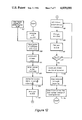
- FIG. 12 is a flow diagram for computing the profile of a ramp constructed according to the principles of the present invention for the workpiece of FIG. 4.
- FIGS. 13a and 13b are profiles of the ramp of FIG. 12.
- Workpiece A rigid body, having a center of gravity and substantially prismatic external contour.
- the cross-sectional shape of the workpiece may be a regular or irregular convex polygon, which may have rounded corners or sides.
- Examples of workpieces include slabs, rectangular boxes, extruded bar stock, hexagonal stock, rods, tubes, cans, rounds loaded pallets, and the like.
- Rotation Angular movement of a workpiece about an axis without translation.
- Centroidal Rotation Angular movement of a workpiece about an axis which passes through its center of gravity without translation.
- the preferred embodiment is the case where the contour of the workpiece comprises entirely planar or flat surfaces.
- workpiece 1 is shown in a position where CG 2 is vertically above corner 3 of workpiece 1 so that CG 2 at its highest point relative to supporting surface 4.
- CG 2 becomes progressively lower in elevation relative to supporting surface 4 and also becomes offset relative to corner 3 thereby creating a moment arm which tends to cause workpiece 1 to drop onto supporting surface 4 due to the force of gravity.
- sufficient force would have to be applied to workpiece 1 to raise CG 2 back to its initial position.
- the work required to accomplish this task equals the difference in elevation from the initial position to the final position times the weight of workpiece 1.
- ramp 5 is designed such that CG 2 is in fact maintained at a constant elevation while workpiece 1 rotates about CG 2, provided CG 2 is permitted to translate horizontally as workpiece 1 rolls on said ramp 5.
- certain limitations must be ascribed to the system. To prevent a moment arm from being created between support 6 of workpiece 1 and CG 2, support 6 must be maintained exactly below CG 2. Further, in order for ramp 5 to rollably support the weight of workpiece 1, slippage, or relative movement, between workpiece 1 and ramp 5 must be prevented. This antislipping constraint also assumes that the locus of points describing the contour of ramp 5 also describes and corresponds to points on the contour of workpiece 1 as it rotates about CG 2. Support point 6 of workpiece 1 instantaneously experiences zero translation relative to ramp 5 when located vertically below CG 2.
- This equation expresses in hyperbolic trigonometric terms a family of curves which describe the contour of the preferred embodiment of the invention where B is the value of the y-coordinate and D is the value x-coordinate of the CG in an orthogonal rectangular coordinate system within the workpiece.
- B is the value of the y-coordinate
- D is the value x-coordinate of the CG in an orthogonal rectangular coordinate system within the workpiece.
- low point 7 corresponds to the position of workpiece 1 when CG 2 is vertically above new corner 3' and the rolling contour of workpiece 1 is subsequently supported on new contour 5'.
- conveyor 10 is designed to intersect the high point of ramp 5 so that workpiece 1 can easily be loaded on to or off of conveyor 10 located adjacent ramp 5.
- a sheet of relatively deformable material is anchored to the surface of the ramp to provide rolling friction for the workpiece to engage while rolling along the ramp.
- deformable material may be a sheet of stiff rubber or neoprene of thickness ranging from 1/16" to 3/16".
- the rolling friction material may be affixed to the ramp or to the workpiece or both.
- the deformable rolling-friction material is not always adhered to the ramp over its entire surface. Rather, as shown in FIG. 11, material 20 is attached to ramp 5 only at high point 22. The remainder of said material lays loosely on ramp 5 until hook 25, which is attached to the lower end of material 20, engages flange 30 on corner 3 of workpiece 1. Then material 20 conforms to the contour of ramps and follows workpiece 1 as it rolls either up or down ramp 5. Hence, material 20 prevents slippage between workpiece 1 and ramp 5 by its rolling friction characteristics. Tension in material 20 between high point 22 and hook 25 created by the weight of workpiece 1 resting in hook 25 further assures that workpiece 1 will not slip just as it begins to engage ramp 5.
- the present invention as described can accommodate any irregularly shaped workpiece provided it comprises planar sides having approximately rounded acute angle corners where necessary.
- the invention can be equally applied to circular or non-circular items with an eccentric CG without changing the design process.
- the designer must first determine the location of the CG relative to the contour of the workpiece.
- the locus of points representing the contour of the ramp must then be determined by differentially following the locus points of support interface 6 of workpiece 1, where CG 2 moves horizontally and where support interface point 6 is always disposed directly below CG 2 and always has zero translation at the instant of contact. This will often require the designer to model the contour of workpiece 1 in order to accomplish the calculus necessary to model the locus of the contour of ramp 5.
- Table I is a complete listing of all of the routines and subroutines of instructions employed in accordance with FIG. 12 to provide a full-scale profile of the contour of a ramp constructed according to the present invention as shown in FIG. 13 for rolling a heavy box having its CG at linear coordinates x and y.
- the present invention includes a method for computing and plotting the profile of the contour of a ramp for rolling a box without changing the vertical height of the CG thereof.
- Block 102 scales the plotter in millimeters. Units of measure on the full scale plotted hardcopy will then be in units of millimeters.
- Block 103 allows the designer to enter the location of the CG within the object into the computer via a keyboard terminal. The location is specified as x and y coordinates (in millimeters) with the origin at the corner of the rotating box.
- Block 104 locates, plots and labels the x and y axes (133 of FIGS. 13A and 13B), which are used as the basis for a plot of the locus of points describing the surface of the ramp. These axes are separate and unique from the axes which are used to locate the CG within the object and which are a frame of reference which moves with the object.
- Block 105 plots out the words "x-coord:” and "y-coord:” and the coordinates of the CG of the rolling object entered by the designer at Block 103 as shown at 134 of FIGS. 13A and 13B.
- Block 107 moves the plotter pen to the origin, where the plot will begain.
- Block 109 of FIG. 12 moves the plotter pen to the newly calculated point on the curve.
- Block 110 of FIG. 12 moves the plotter pen vertically downward to the x-axis to provide contrast for the profile of the ramp.
- Block 111 of FIG. 12 is a decision mode. If the value calculated for F(x) is less than 0, then the program moves to Block 112. If the value of F(x) is zero or greater the program returns to Block 108, and new values for x and F(x) are calculated per Block 108. Thus, the entire ramp profile is produced.
- Block 112 of FIG. 12 locates, plots and labels the line which the CG will follow as workpiece 1 rolls along the ramp. This is shown by 135 of FIGS. 13A and 13B.
- Block 113 of FIG. 12 draws the contour of the object to be rotated, in the case of the preferred embodiment, rectangular box 1 balanced at the maximum point of the plotted curve, 131 in FIG. 13A.
- the CG is located and labeled within the rectangular box.
- Block 114 of FIG. 12 plots additional curves, required to correspond with the remaining sides of the object plotted in Block 113.
- FIGS. 13a and 13b illustrate the versatility of the present invention.
- the profile of a ramp is shown for horizontally translating a box from two different starting orientations.
- ramp 131 is specified for the larger side of workpiece 1
- ramp 132 is specified for the shorter side of workpiece 1 with respect to the starting orientation of workpiece 1.
- a ramp designed in accordance with the principles of the present invention receives a workpiece at a point where the relative geometries correspond and rolling friction material is aligned to prevent relative slippage. Once aligned, the workpiece can be rolled along the ramp by simply applying sufficient force to overcome torsional momentum and rolling friction at its point or line of contact with the ramp's surface.
- the ramp of the present invention always provides support for the workpiece at a contact point or line orthogonal to the direction of horizontal translation of the workpiece without change of the elevation of the CG. Obviously, since the CG always remains over the point of contact, the workpiece is always balanced. Hence, the workpiece can be stopped, and it will remain, at any point and in any rotational orientation during translation along the ramp.
Landscapes
- Bending Of Plates, Rods, And Pipes (AREA)
Abstract
Description
Claims (11)
Priority Applications (1)
| Application Number | Priority Date | Filing Date | Title |
|---|---|---|---|
| US06/441,933 US4609090A (en) | 1982-11-18 | 1982-11-18 | Method and apparatus for moving and handling heavy objects |
Applications Claiming Priority (1)
| Application Number | Priority Date | Filing Date | Title |
|---|---|---|---|
| US06/441,933 US4609090A (en) | 1982-11-18 | 1982-11-18 | Method and apparatus for moving and handling heavy objects |
Publications (1)
| Publication Number | Publication Date |
|---|---|
| US4609090A true US4609090A (en) | 1986-09-02 |
Family
ID=23754873
Family Applications (1)
| Application Number | Title | Priority Date | Filing Date |
|---|---|---|---|
| US06/441,933 Expired - Fee Related US4609090A (en) | 1982-11-18 | 1982-11-18 | Method and apparatus for moving and handling heavy objects |
Country Status (1)
| Country | Link |
|---|---|
| US (1) | US4609090A (en) |
Cited By (1)
| Publication number | Priority date | Publication date | Assignee | Title |
|---|---|---|---|---|
| US5588354A (en) * | 1995-09-21 | 1996-12-31 | Marshall Air Systems, Inc. | Apparatus for conveyorized griddle-like cooking of food products |
Citations (7)
| Publication number | Priority date | Publication date | Assignee | Title |
|---|---|---|---|---|
| US2420130A (en) * | 1944-10-31 | 1947-05-06 | George H Foss | Apparatus for jacking up and lowering motor vehicle wheels |
| US2499499A (en) * | 1948-05-29 | 1950-03-07 | Harry W Hedburg | Tipover device |
| US2500361A (en) * | 1948-03-08 | 1950-03-14 | Arthur K Jordan | Baker's dump table |
| US3033052A (en) * | 1960-01-28 | 1962-05-08 | Ibm | Balanced speed-varying mechanism |
| US3361418A (en) * | 1964-03-03 | 1968-01-02 | Marguerite S.C. Fromont | Device for imparting rotational and transitional movements to products being treatedin thermic appliances |
| US3693954A (en) * | 1971-04-05 | 1972-09-26 | Koppers Co Inc | Cooling bed |
| DE2907839A1 (en) * | 1978-03-01 | 1979-09-06 | Kobe Steel Ltd | DEVICE FOR TRANSFERRING LONGITUDINAL MATERIAL |
-
1982
- 1982-11-18 US US06/441,933 patent/US4609090A/en not_active Expired - Fee Related
Patent Citations (7)
| Publication number | Priority date | Publication date | Assignee | Title |
|---|---|---|---|---|
| US2420130A (en) * | 1944-10-31 | 1947-05-06 | George H Foss | Apparatus for jacking up and lowering motor vehicle wheels |
| US2500361A (en) * | 1948-03-08 | 1950-03-14 | Arthur K Jordan | Baker's dump table |
| US2499499A (en) * | 1948-05-29 | 1950-03-07 | Harry W Hedburg | Tipover device |
| US3033052A (en) * | 1960-01-28 | 1962-05-08 | Ibm | Balanced speed-varying mechanism |
| US3361418A (en) * | 1964-03-03 | 1968-01-02 | Marguerite S.C. Fromont | Device for imparting rotational and transitional movements to products being treatedin thermic appliances |
| US3693954A (en) * | 1971-04-05 | 1972-09-26 | Koppers Co Inc | Cooling bed |
| DE2907839A1 (en) * | 1978-03-01 | 1979-09-06 | Kobe Steel Ltd | DEVICE FOR TRANSFERRING LONGITUDINAL MATERIAL |
Cited By (1)
| Publication number | Priority date | Publication date | Assignee | Title |
|---|---|---|---|---|
| US5588354A (en) * | 1995-09-21 | 1996-12-31 | Marshall Air Systems, Inc. | Apparatus for conveyorized griddle-like cooking of food products |
Similar Documents
| Publication | Publication Date | Title |
|---|---|---|
| Jeong et al. | Kinematics and workspace analysis of a parallel wire mechanism for measuring a robot pose | |
| CN212551130U (en) | Front material supporting device of numerical control bending machine | |
| US5510977A (en) | Method and apparatus for measuring features of a part or item | |
| US5379987A (en) | Adapter for a jacking device | |
| US4609090A (en) | Method and apparatus for moving and handling heavy objects | |
| WO2001041546A3 (en) | Geometric model database for use in ubiquitous computing | |
| Katsoulas¹ et al. | An efficient depalletizing system based on 2D range imagery | |
| CN212099992U (en) | Oil tank protection device for oil storage and transportation | |
| KR20100063369A (en) | Hands position inspection apparatus and method of articulated robot | |
| JP2000131047A (en) | Shape measurement method for plate-like articles | |
| Chen et al. | Deformation identification and estimation of one‐dimensional objects by vision sensors | |
| CN222098641U (en) | Clamping device and warehousing system | |
| EP4003640B1 (en) | Platform for conveying work parts in an assembly line, and method for placing work parts on the same | |
| CN213230495U (en) | Device for grabbing storage box from bin cabinet by using mechanical arm | |
| CN2355322Y (en) | Turnover plate flexere support assembly | |
| CN223719090U (en) | Plank terminal surface grinding device of beverage bottle packing box | |
| Kotiveerachari et al. | Study of some aspects of burnishing | |
| Ngan et al. | A non-contact technique for the on-site inspection of molds and dies polishing | |
| CN221050366U (en) | Workpiece transferring structure | |
| CN215363285U (en) | Anti-static transmission device for electronic component | |
| CN217276477U (en) | Finished product wine checking machine | |
| CN223575306U (en) | Multi-dimensional cargo size and weight integrated detection device | |
| EP0604380B1 (en) | A co-ordinate measuring machine | |
| CN220729198U (en) | Novel three-coordinate tool | |
| Wang et al. | Square punch forming: section analysis and bending study |
Legal Events
| Date | Code | Title | Description |
|---|---|---|---|
| AS | Assignment |
Owner name: MCILVAINE, GEORGE VICTOR Free format text: ASSIGNMENT OF ASSIGNORS INTEREST.;ASSIGNOR:BAKER, THOMPSON A.;REEL/FRAME:004127/0169 Effective date: 19830103 Owner name: UEBELACKER, WALTER URBAN Free format text: ASSIGNMENT OF ASSIGNORS INTEREST.;ASSIGNOR:BAKER, THOMPSON A.;REEL/FRAME:004127/0169 Effective date: 19830103 |
|
| AS | Assignment |
Owner name: MCILVAINE, GEORGE VICTOR Free format text: ASSIGNMENT OF ASSIGNORS INTEREST.;ASSIGNOR:UEBELACKER, WALTER U;REEL/FRAME:004311/0022 Effective date: 19841004 |
|
| REMI | Maintenance fee reminder mailed | ||
| LAPS | Lapse for failure to pay maintenance fees | ||
| STCH | Information on status: patent discontinuation |
Free format text: PATENT EXPIRED DUE TO NONPAYMENT OF MAINTENANCE FEES UNDER 37 CFR 1.362 |
|
| FP | Expired due to failure to pay maintenance fee |
Effective date: 19900902 |