US460752A - Island - Google Patents
Island Download PDFInfo
- Publication number
- US460752A US460752A US460752DA US460752A US 460752 A US460752 A US 460752A US 460752D A US460752D A US 460752DA US 460752 A US460752 A US 460752A
- Authority
- US
- United States
- Prior art keywords
- spring
- disk
- dial
- numerals
- arm
- Prior art date
- Legal status (The legal status is an assumption and is not a legal conclusion. Google has not performed a legal analysis and makes no representation as to the accuracy of the status listed.)
- Expired - Lifetime
Links
- 230000009471 action Effects 0.000 description 3
- 230000006872 improvement Effects 0.000 description 2
- MBEVSMZJMIQVBG-UHFFFAOYSA-N 2-(hydroxymethyl)guanidine Chemical compound NC(N)=NCO MBEVSMZJMIQVBG-UHFFFAOYSA-N 0.000 description 1
- 241000220010 Rhode Species 0.000 description 1
- 241001251753 Riparia cincta Species 0.000 description 1
- 230000004075 alteration Effects 0.000 description 1
- 238000010276 construction Methods 0.000 description 1
- 230000007547 defect Effects 0.000 description 1
- 230000000694 effects Effects 0.000 description 1
- 230000007246 mechanism Effects 0.000 description 1
- 238000000034 method Methods 0.000 description 1
- 230000004048 modification Effects 0.000 description 1
- 238000012986 modification Methods 0.000 description 1
Images

Classifications
-
- G—PHYSICS
- G04—HOROLOGY
- G04B—MECHANICALLY-DRIVEN CLOCKS OR WATCHES; MECHANICAL PARTS OF CLOCKS OR WATCHES IN GENERAL; TIME PIECES USING THE POSITION OF THE SUN, MOON OR STARS
- G04B19/00—Indicating the time by visual means
- G04B19/06—Dials
- G04B19/16—Shiftable dials, e.g. indicating alternately from 1 to 12 and from 13 to 24
- G04B19/163—Shiftable dials, e.g. indicating alternately from 1 to 12 and from 13 to 24 numbers which are visible alternately from 1 to 12 and from 13 to 24 on the same dial G04B19/085
Definitions
- My invention is applicable to all kinds of clock and watch work, and also to electric and pneumatic clocks; and the object of my invention is to produce attachments for such time-pieces, whereby without altering their working parts to indicate time on the twentyfour hour system in a manner which shall avoid all difficulty in reading the dial, and at the same time preserve the usual appearance of the dial-face.
- the same consists in the provision of a disk carrying numbers from one to twelve,-arranged alternately with numbers from thirteen to twentyfour and disposed in a single continuous annular series, the said disk being pivoted movably upon a dial-face having an annular series of twelve apertures, through which the numbers of each series are periodically exposed to view.
- My invention further consists in the provision of certain spring attachments for imparting the required movements to the disk.
- My invention still further consists in the provision of an attachment to the clock-work for automatically bringing the springs into action at required intervals, all as hereinafter described and claimed.
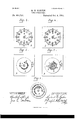
- Figure 1 is a front elevation of a clock mechanism with a portion of my improvement applied.
- Fig. 2 is a transverse vertical section of the same with the dial attached, the latter being also shown in section.
- Figs. 3, 3 8, and 3 are detached views of the actuating-arm in various positions.
- Fig. at is a front elevation of my improved dial set to indicate ante-meridian time.
- Fig. 5 is a rear elevation of the same.
- Fig. 6 is a front elevation of my improved dial set to indicate post-meridian time.
- Fig. 7 is a rear view of the same.
- Fig. 8 is a front elevation of the movable disk.
- A designates the dialface, which may be either square, as shown in the drawings, or round, orof any othersuitable or preferred form.
- said dial-face is formed with an annular series of apertures a, either angular, round, oval, or otherwise, twelve in number.
- Said dial-face is also formed with the central aperture (if for the hand-arbors, and, in some cases, with the aperture a for the winding-arbor.
- This disk designates the movable disk, which is formed with the central aperture 1) for the hand-arbors, and in some cases with the elongated aperture 1) for the winding-arbor.
- This disk which is preferably circular, is pivoted upon the rear side of the face A by a hollow pivot c, and is of such diameter as to cover the apertures a, of said face.
- the disk also carries upon the side contiguous to face A a series of numerals, beginning with the nu Ineral 1 and ending with the numeral 24-. These numerals are not arranged consecutively, but run in order from 1 to 12, while the spaces between these numerals are occupied by numerals running from 13 (which is between 12 and 1) to 24 (which is between 11 and 12).
- the two series of numerals alternate with each other.
- the apertures a are of such size as to clearly expose one set of numerals, while such apertures are placed at such distance apart that the numerals of the alternate series shall be completely concealed.
- the disk In order to expose first one series of numerals and then the other, the disk mustmove to the right and then to the left a distance equal to the width of the apertures at. These movements of the disk are caused by springs d and 6. These springs are secured at one end to the dial-face A, and act in opposite directions upon the disk B, the spring 61 being sufficiently more powerful than spring 6 to move said disk against the action of spring 6.
- the spring 6 is permanently attached to disk 13, while spring (1 works at its free end in a slot b which is formed in the disk B.
- the free end of spring (2 is bent inward at right angles, so as to pass through the slot W.
- This slot has at one end a lateral extension which forms a shoulder upon the disk.
- Anotch Z1 is formed upon the -periphery of disk B and works in conjunction with a stop a upon the dial A, so as to limit the movements of the disk.
- F designates an arm, which is shown as secured upon the hour-hand arbor by a sleeve f, similar in character to the sleeves generally used in securing hour-hands upon their arbors; but said arm may be keyed upon the arbor or secured removably thereon in any way, or said arm may be formed upon the arbor.
- a cam-extension f At the inner part of this arm near to the sleeve is formed a cam-extension f, while a pawl f having a cam-surface disposed oppositely to the cam-surface of extension f, is pivoted near the outer end of the arm.
- the extension f and pawl f are upon that side of arm F which is contiguous to the inner side of disk B.
- pawl f Upon the outer extremity of arm F is placed or formed a stop f and a stop f opposite to stop f and having a screw-stud The outer end of pawl f works between these stops, and said pawl is held in engagement with stop f by a spring f", which is coiled around the pivot of the pawl and one end of which is secured to the pawl, while the opposite end is secured to the arm.
- the arm F will have moved so as to bring the pawl into engagement with the end of spring (1, which is in the extension of slot b and as the arm F continues to move the end of the spring d will ride upon the canrsurlace of the pawl, and thus at twelve oclock midday be drawn out of the extension of the slot, whereupon the spring 0 will throw the disk so as to conceal the series of numerals from 1 to 12 and expose the series of numerals from 13 to 24.
- the attachment is capable of being readily applied to all kinds of clock and watch movements and also to electric and pneumatic clocks without involving any changes in the working parts.
Landscapes
- Physics & Mathematics (AREA)
- General Physics & Mathematics (AREA)
- Electromechanical Clocks (AREA)
Description
(No Model.) 2 Sheets-Sheet 1.
M. B. MARTIN. TIME PIECE DIAL.
No. 460,752. Patented Oct. 6, 1891;
WIT-M55555. INVIN/ZUH.
jiff if (No Model.) 2 Sheets-Sheet 2.
M. B. MARTIN.
TIME PIEGE DIAL. No. 460,752. Patented Oct. 6, 1891.
Figr. Fig. 6
WTTNEEEIE j INVINTUH.
UNITED STATES PATENT OFFICE.
MICHAEL B. MARTIN, OF PROVIDENCE, RHODE ISLAND.
TIME-PIECE DIAL.
SPECIFICATION forming part of Letters Patent No. 460,752, dated October 6, 1891.
Application filed February 10, 1886. Serial No. 155,466. (No model.)
To all whmn it may concern.-
Be it known that I, MICHAEL B. MARTIN, of
the city and county of Providence, and State of Rhode Island, have invented a new and useful Improvement in Time-Pieces, of which the following is a full, clear, and exact description, reference being had to the accompanying drawings, forming a part of this specification.
My invention is applicable to all kinds of clock and watch work, and also to electric and pneumatic clocks; and the object of my invention is to produce attachments for such time-pieces, whereby without altering their working parts to indicate time on the twentyfour hour system in a manner which shall avoid all difficulty in reading the dial, and at the same time preserve the usual appearance of the dial-face.
Heretofore various attempts have been made to indicate the lapse of time in a day by dividing the dials into spaces represent ing twenty-four hours; but this object has either necessitated changes in the working parts of the clock or has rendered the dial difficult to read. By virtue of my invention I overcome these defects and provide celtain simple attachments requiring no alteration in the clock-work, nor any duplication of the number or arrangement of figures upon the dial, and at the same time indicating plainly the lapse of the twenty-four hours comprised in a calendar day. This being the object of my invention, the same consists in the provision of a disk carrying numbers from one to twelve,-arranged alternately with numbers from thirteen to twentyfour and disposed in a single continuous annular series, the said disk being pivoted movably upon a dial-face having an annular series of twelve apertures, through which the numbers of each series are periodically exposed to view.
My invention further consists in the provision of certain spring attachments for imparting the required movements to the disk.
My invention still further consists in the provision of an attachment to the clock-work for automatically bringing the springs into action at required intervals, all as hereinafter described and claimed.
In order that my invention may be fully understood, I will proceed to describe itwith reference to the accompanying drawings, in which Figure 1 is a front elevation of a clock mechanism with a portion of my improvement applied. Fig. 2 is a transverse vertical section of the same with the dial attached, the latter being also shown in section. Figs. 3, 3 8, and 3 are detached views of the actuating-arm in various positions. Fig. at is a front elevation of my improved dial set to indicate ante-meridian time. Fig. 5 is a rear elevation of the same. Fig. 6 is a front elevation of my improved dial set to indicate post-meridian time. Fig. 7 is a rear view of the same. Fig. 8 is a front elevation of the movable disk.
In the said drawings, A designates the dialface, which may be either square, as shown in the drawings, or round, orof any othersuitable or preferred form. In any event, said dial-face is formed with an annular series of apertures a, either angular, round, oval, or otherwise, twelve in number. Said dial-face is also formed with the central aperture (if for the hand-arbors, and, in some cases, with the aperture a for the winding-arbor.
B designates the movable disk, which is formed with the central aperture 1) for the hand-arbors, and in some cases with the elongated aperture 1) for the winding-arbor. This disk, which is preferably circular, is pivoted upon the rear side of the face A by a hollow pivot c, and is of such diameter as to cover the apertures a, of said face. The disk also carries upon the side contiguous to face A a series of numerals, beginning with the nu Ineral 1 and ending with the numeral 24-. These numerals are not arranged consecutively, but run in order from 1 to 12, while the spaces between these numerals are occupied by numerals running from 13 (which is between 12 and 1) to 24 (which is between 11 and 12). Thus it will be seen that the two series of numerals alternate with each other. The apertures a are of such size as to clearly expose one set of numerals, while such apertures are placed at such distance apart that the numerals of the alternate series shall be completely concealed. In order to expose first one series of numerals and then the other, the disk mustmove to the right and then to the left a distance equal to the width of the apertures at. These movements of the disk are caused by springs d and 6. These springs are secured at one end to the dial-face A, and act in opposite directions upon the disk B, the spring 61 being sufficiently more powerful than spring 6 to move said disk against the action of spring 6. The spring 6 is permanently attached to disk 13, while spring (1 works at its free end in a slot b which is formed in the disk B. The free end of spring (2 is bent inward at right angles, so as to pass through the slot W. This slot has at one end a lateral extension which forms a shoulder upon the disk. Anotch Z1 is formed upon the -periphery of disk B and works in conjunction with a stop a upon the dial A, so as to limit the movements of the disk. Thus it will be seen that if the free end of spring d be carried forward and into the extension of slot b the spring (1, being more powerful than spring e, will contract and move the disk backward as far as the notch 11 will permit, and that if spring (1 be released from the extension the spring will throw the disk forward as far as the notch will permit. When the spring (I is out of the extension of slot 11 the disk exposes the series of numerals from 12 to 1, while when spring cl is in said notch the series of numerals from 13 to 2% are exposed. In order to effect these movements of the spring (Z and disk B,I employ an attachment for the hourhand arbor, which I will now proceed to describe.
F designates an arm, which is shown as secured upon the hour-hand arbor by a sleeve f, similar in character to the sleeves generally used in securing hour-hands upon their arbors; but said arm may be keyed upon the arbor or secured removably thereon in any way, or said arm may be formed upon the arbor. At the inner part of this arm near to the sleeve is formed a cam-extension f, while a pawl f having a cam-surface disposed oppositely to the cam-surface of extension f, is pivoted near the outer end of the arm. The extension f and pawl f are upon that side of arm F which is contiguous to the inner side of disk B. Upon the outer extremity of arm F is placed or formed a stop f and a stop f opposite to stop f and having a screw-stud The outer end of pawl f works between these stops, and said pawl is held in engagement with stop f by a spring f", which is coiled around the pivot of the pawl and one end of which is secured to the pawl, while the opposite end is secured to the arm.
By reference to Figs. 3, 3", 3, and 3 the action of the arm F upon spring 61 will be clearly understood. In Fig. 3 the arm F, moving with the hour-hand, is in the position which it occupies at forty minutes past twenty-two p. 111., or forty minutes past ten o'clock pm. by the usual method of time:
dial reading. In this position the free end of spring (Z has just been engaged by the extension f. The arm F continues to move in the direction indicated by the arrow and carries the spring end along the slot b till at -thirty minutes past twelve a. m., or thirty minutes past twenty-four oclock, (see Fig. 3",) the end of the spring (Z will have been carried by extension f into the extension of the slot and extension f will have passed sufficiently to clear the spring (I, the result being that at half an hour past midnight the spring d will throw the disk so as to conceal the series of numerals from 13 to 2% and ex.- pose the numerals from I to 12. At forty minutes past eleven oclock a. m. the arm F will have moved so as to bring the pawl into engagement with the end of spring (1, which is in the extension of slot b and as the arm F continues to move the end of the spring d will ride upon the canrsurlace of the pawl, and thus at twelve oclock midday be drawn out of the extension of the slot, whereupon the spring 0 will throw the disk so as to conceal the series of numerals from 1 to 12 and expose the series of numerals from 13 to 24.
By virtue of this invention but one series of numerals is presented at the same time, and consequently no confusion can occur in reading the dial, while the changes in the numerals are made with the utmost certainty. The attachment is capable of being readily applied to all kinds of clock and watch movements and also to electric and pneumatic clocks without involving any changes in the working parts.
I do not wish to be understood as intending to confine myself toprecise details of construction, as various modifications in such details may be made without departing from the essential spirit of my invention.
Having thus described my invention, I claim as new and desire to secure by Letters Patent- 1. In a time-piece, as herein described, the combination, with the hour-hand arbor, of the arm F, carrying the extension f, and stops f f", the spring-pawl f and stop f, as described.
2. The combination, with dial A, having apertures a, and the disk B, having the alternating series of figures and centrally pivoted upon dial A, of the slot b and springs (l e, as described.
3. The combination, with the fixed and movable dials and the springs of greater and less power, of the arm F, carrying the extension f and stops f f, the spring-pawl f and stop f as set forth.
In witness whereof I have hereunto set my hand.
MICHAEL E. MARTIN.
\Vitnesses:
M. F. BLIGH, J. A. MILLER, J r.
Applications Claiming Priority (1)
| Application Number | Priority Date | Filing Date | Title |
|---|---|---|---|
| US460752TA | 1885-02-10 | 1885-02-10 |
Publications (1)
| Publication Number | Publication Date |
|---|---|
| US460752A true US460752A (en) | 1891-10-06 |
Family
ID=32925370
Family Applications (1)
| Application Number | Title | Priority Date | Filing Date |
|---|---|---|---|
| US460752D Expired - Lifetime US460752A (en) | 1885-02-10 | 1885-02-10 | Island |
Country Status (1)
| Country | Link |
|---|---|
| US (1) | US460752A (en) |
-
1885
- 1885-02-10 US US460752D patent/US460752A/en not_active Expired - Lifetime
Similar Documents
| Publication | Publication Date | Title |
|---|---|---|
| US1950189A (en) | Timepiece | |
| US1650123A (en) | Timepiece | |
| US304281A (en) | russell | |
| CN109964179B (en) | time zone indicator device | |
| US3524313A (en) | Tide clock | |
| US2677928A (en) | Tide-indicating mechanism | |
| US563268A (en) | Perpetual calendar for watches or clocks | |
| US359227A (en) | pallweber | |
| US3537255A (en) | Day-date watch | |
| DE69810261D1 (en) | Large date display mechanism for clockwork and pendulum clockworks and clockwork provided with such a mechanism | |
| US239738A (en) | Louis dee | |
| US3712043A (en) | Day-date timepiece with multiple display of dates and days of week | |
| US312754A (en) | pallwebee | |
| US3780526A (en) | Timepiece including a color cylinder and another time indicator displayed on a different plane | |
| US555387A (en) | Clock | |
| US329078A (en) | Heney l | |
| US1234829A (en) | Alarm-clock. | |
| US2658329A (en) | Electrically wound and set watch | |
| US615719A (en) | Dial-train for watches or other purposes | |
| US2024066A (en) | Geographical clock | |
| US458745A (en) | Half to john hardy | |
| US3373558A (en) | Calendar clock or watch | |
| US188865A (en) | Improvement in alarm-clocks | |
| RU126152U1 (en) | CLOCK WITH ONE ARROW FOR SEPARATE INDICATION OF THE CURRENT HOUR IN THE MODE OF THE INDICATION OF THE HOUR OR MINUTES OF THE CURRENT HOUR IN THE MODE OF THE INDICATION OF MINUTES | |
| US222377A (en) | Improvement in calendar-clocks |