US4605960A - Method for avoiding identifying perimeter variations as blemishes in a CCD image - Google Patents
Method for avoiding identifying perimeter variations as blemishes in a CCD image Download PDFInfo
- Publication number
- US4605960A US4605960A US06/663,699 US66369984A US4605960A US 4605960 A US4605960 A US 4605960A US 66369984 A US66369984 A US 66369984A US 4605960 A US4605960 A US 4605960A
- Authority
- US
- United States
- Prior art keywords
- pixel
- pixels
- perimeter
- motions
- detected
- Prior art date
- Legal status (The legal status is an assumption and is not a legal conclusion. Google has not performed a legal analysis and makes no representation as to the accuracy of the status listed.)
- Expired - Lifetime
Links
Images


Classifications
-
- G—PHYSICS
- G01—MEASURING; TESTING
- G01N—INVESTIGATING OR ANALYSING MATERIALS BY DETERMINING THEIR CHEMICAL OR PHYSICAL PROPERTIES
- G01N21/00—Investigating or analysing materials by the use of optical means, i.e. using sub-millimetre waves, infrared, visible or ultraviolet light
- G01N21/84—Systems specially adapted for particular applications
- G01N21/88—Investigating the presence of flaws or contamination
-
- H—ELECTRICITY
- H04—ELECTRIC COMMUNICATION TECHNIQUE
- H04N—PICTORIAL COMMUNICATION, e.g. TELEVISION
- H04N23/00—Cameras or camera modules comprising electronic image sensors; Control thereof
- H04N23/80—Camera processing pipelines; Components thereof
- H04N23/81—Camera processing pipelines; Components thereof for suppressing or minimising disturbance in the image signal generation
Definitions
- This invention relates generally to CCD (charge coupled device) imaging and particularly to a method for avoiding the identification of perimeter variations as blemishes in the proximity of the perimeter of an image on a CCD.
- the image pixels immediately adjacent to the perimeter pixels are identified and their addresses held in memory irrespective of the orientation of the image and the size of the image.
- the present invention is cast into the environment of detecting the perimeter of a black matrix on the inside surface of a CRT faceplate panel.
- This environment was selected when describing the present invention because the invention is an improvement of the inventions described in the referenced patent and patent applications and those inventions are described in that environment. Nevertheless it will be understood by those skilled in the art that the present invention is useful in distinguishing permissible perimeter variations from blemishes in the proximity of the perimeter of any image cast onto a CCD.
- a method of avoiding the identification of permissible variations in the perimeter of an image on a CCD (charge coupled device) as blemishes in the proximity of the perimeter includes defining the consideration of adjacent perimeter identifying pixels as pixel motions.
- Adjacent pixels are pixels having contiguous sides or contiguous corners. In a pixel direction matrix, the pixel under consideration is surrounded by adjacent pixels whereby side contiguous pixels result in straight pixel motions and corner adjacent pixels result in diagonal pixel motions.
- a plurality of adjacent pixels is sequentially considered and diagonal pixel motions are recorded as straight pixel motions where the first and last pixel motions are diagonal in opposite directions and all intervening pixel motions are straight.
- FIG. 1 shows the perimeter of the black matrix present on the inside surface of a faceplate panel.
- FIG. 2 is a simplified showing of a CCD based image inspection system.
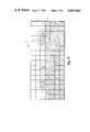
- FIG. 3 is an enlarged portion of the black matrix perimeter of FIG. 1 showing how permissible perimeter variations can be erroneously detected as blemishes in the proximity of the perimeter.
- FIG. 4 shows the relationship of the X and Y axes with the perimeter and defines the directions of pixel consideration along the axes.
- FIGS. 5a to 5f show several types of permissible variations which could be erroneously identified as blemishes, when considering the vertical, or Y, portions of the perimeter.
- FIGS. 6a to 6f show several types of permissible variations which could be erroneously identified as blemishes when considering the horizontal, or X, portions of the perimeter.
- FIG. 7 shows how the pixel directions of the motions are defined.
- FIGS. 8a and 8b are a flow chart of a preferred method of distinguishing permissible perimeter variations from blemishes in the proximity of the perimeter.
- the inside surface of a CRT faceplate panel 11 includes a black matrix which is composed of a plurality of parallel black lines 12 and a perimeter 13.
- the parallel lines 12 extend across the entire surface of the panel 11 and only several are shown for simplicity.
- Phosphors are arranged in the spaces between the matrix lines 12 in a sequential fashion and each phosphor emits a different color of light when impacted with electrons.
- the phosphors are arranged in a repetitive pattern such as red, green and blue across the entire inside surface of the panel 11 to form a screen 14.
- FIG. 2 shows a CCD based inspection system 15 which can be of the type described in U.S. Pat. No. 4,454,545.
- the inspection system 15 includes a light source 16 the light rays 17 of which fully illuminate the phosphor screen 14 on the inside surface of the panel 11.
- the light rays 17 pass through the phosphor screen and are focused by a lens 18 onto the CCD 19 within a CCD camera 21.
- Each pixel of the CCD 19 in the camera 21 is charged to a particular level depending upon the amount of light received by the individual pixels.
- the pixels receiving light passing through the screen 14 are charged to a different level than the pixels shaded by the perimeter 13.
- the pixel data are transferred from the CCD 19 to a central processing unit 22 and processed in accordance with the inspection being made.
- the inspection can be the detection of blemishes in the screen 14 as described in U.S. Pat. No. 4,454,545 while utilizing the perimeter plotting described in the above-referenced U.S. Pat. No. 4,575,751
- the detection of blemishes in the proximity of the perimeter 13 described in the above-referenced application Ser. No. 663,153 and the method of avoiding identifying permissible perimeter variations as blemishes described hereinafter also are carried out in the CPU 22.
- FIG. 3 is a greatly magnified view of the rectangular portion 23 of the perimeter 13 of FIG. 1.
- the cross-hatched blocks represent pixels which are shaded by the perimeter 13.
- the clear blocks represent pixels receiving light through the phosphor screen 14.
- the pixels alphabetically labeled A-P represent the pixels which are identified as bordering the perimeter 13 utilizing the perimeter plotting described in U.S. Pat. No. 4,575,751.
- Application Ser. No. 663,153 describes a method of detecting blemishes in the proximity of the perimeter 13 to avoid the blemishes being identified as part of the perimeter 13.
- each motion direction can be straight, or can turn either clockwise or counterclockwise. Any number of clockwise turning motions or straight motions is acceptable but a blemish indication is provided upon the occurrence of two counterclockwise turning motions without an intervening clockwise turning motion.
- the pixel directions are provided to the CPU 22 and used to identify blemishes in the proximity of the perimeter 13 in a manner fully described in the application Ser. No. 663,153.
- the pixels 30, 31 and 32 would be identified as a blemish despite the fact that they are a permissible perimeter variation.
- consideration of pixels L, M, N, O around the pixels 34 and 35 also would result in a blemish indication.
- the method described herein avoids these erroneous blemish indications and thus the hereindescribed method is executed prior to the execution of the blemish detection method described in application Ser. No. 663,153.
- FIG. 4 shows that the entire perimeter 13 is positioned beneath the horizontal X axis and to the right of the vertical Y axis. Additionally, FIG. 4 shows that the X values increase moving to the right away from the origin O and the Y pixel values increase going downwardly away from the origin O.
- FIGS. 5a to FIG. 5f show several permissible perimeter variations which can be erroneously identified as perimeter boardering blemishes. Any of the variations shown in FIG. 5a to 5f can occur when moving downwardly along the right portion of the perimeter 13, as shown in FIG. 1, or when moving upwardly along the left portion of the perimeter 13.
- FIGS. 6a to 6f show permissible perimeter variations similar to those shown in FIGS. 5a to 5c but which can be encountered when moving horizontally, either right or left, along the top and bottom portions of the perimeter 13. In FIGS.
- FIGS. 5a to 5f and 6a to 6f the pixels labeled X 1 , Y 1 , are the first pixel considered in a group of pixels and those labeled X 5 ,Y 5 are the last pixel considered.
- FIGS. 5a, 5c and 5e represent downward motion while FIGS. 5b, 5d and 5f represent upward motion.
- FIGS. 6a to 6c represent horizontal motion to the right and 6d to 6f to the left.
- these directions are exemplary only and any of the FIGS. 5a to 5f patterns can be encountered when going in either vertical direction, and any of the FIGS. 6a to 6f patterns can be encountered when going in either horizontal direction.
- FIG. 7 shows how the pixel directions which are provided to the CPU 22 are defined. These pixel motions are used to calculate the clockwise, counterclockwise and straight motion directions.
- the central pixel is identified X 1 ,Y 1 and thus is representative of the similarly identified pixels in FIGS. 5a and 5f and 6a to 6f.
- pixel X 1 ,Y 1 of FIG. 7 corresponds to pixel F of FIG. 3
- the next perimeter defining pixel is pixel G.
- a D3 pixel motion would be provided to the CPU 22.
- the central pixel X 1 ,Y 1 corresponds to pixel G of FIG.
- a D4 pixel direction is provided to the CPU 22.
- the D3 and D4 pixel motions are processed by the CPU 22 to provide a clockwise turning motion in accordance with the method described in application Ser. No. 663,153.
- the pixel motion defining matrix shown in FIG. 7 moves around the perimeter 13 as the central pixel X 1 ,Y 1 is sequentially changed to correspond to the various perimeter defining pixels of FIG. 3.
- the orientation of the matrix with respect to the horizontal (X) and vertical (Y) axes remains unchanged as the matrix moves around the perimeter 13.
- the method described herein identifies the permissible perimeter variations shown in FIGS. 5a to 5f and 6a to 6f by first comparing the horizontal, or X, locations of a selected plurality of consecutive pixels and then comparing the vertical, or Y, locations of the same pixels.
- the actual pixel directions are ignored and one of the pixel directions 0, 2, 4 or 6 of FIG. 7 is provided to the CPU 22.
- the pixel motion from pixel to pixel is a D1 direction as shown in FIG. 7.
- the consideration going from pixel X 2 ,Y 2 to pixel X 3 ,Y 3 is a D3 motion as shown in FIG. 7.
- the X 2 ,Y 2 pixel serves as the central pixel X 1 ,Y.sub. 1 in the FIG. 7 matrix. That is, the matrix is shifted one pixel downwardly and to the right. Because the pixel arrangement of FIG. 5a is a permissible perimeter variation the actual D1 and D3 motions are ignored and two consecutive D2 motions are provided to the CPU 22.
- FIG. 8a is a flow chart of a method when the pixels on the vertical right and left sides of the perimeter 13 are under consideration.
- the method starts at step 36 and at step 37 the addresses of the next five pixels to be considered are provided.
- the addresses of these five pixels have previously been made available to the CPU 22 by the perimeter plotting subsystem described in copending application Ser. No. 551,920.
- the horizontal, or X, positions of the first two pixels are compared. When the horizontal position of these two pixels is the same, the pixels are vertically aligned and step 37 is returned to and the next succeeding pixel becomes the central pixel in the matrix of FIG. 7.
- step 39 is entered and the horizontal positions of the first and third pixels are compared.
- step 40 is entered to compare the vertical positions of the first and third pixels.
- the motion is upwardly along the left side of the perimeter 13 and two D6 motions are provided to the CPU 22 in accordance with the matrix of FIG. 7, rather than the actual D1 and D3 pixel motions.
- the testing is occurring downwardly on the right side of the perimeter 13.
- two D2 motions are provided to the CPU 22.
- the corrective motions provided at step 41 and/or 42 prevent a single pixel, such as pixel 33 in FIG. 3, from being identified as a blemish.
- step 43 is entered and the horizontal positions of the first and fourth pixels are compared.
- Step 44 is then entered to compare the vertical positions of the first and fourth pixels, and when the first pixel is further from the X axis than the fourth pixel, the motion is upwardly and three D6 pixel motions are provided at step 46.
- step 45 is entered and three D2 pixel motions are provided to the CPU 22.
- Step 37 is then reentered for consideration of the next five pixels.
- step 47 is entered to compare the horizontal positions of the first and fifth pixels.
- the motion can be either around a corner or along the horizontal axis and step 49 is entered to begin the horizontal investigation.
- step 48 is entered and the horizontal positions of the second, third and fourth pixels are compared to determine whether or not whether one of the patterns of FIGS. 5e and 5f is present. When such a pattern is not indicated, the motion is either around a corner or along the horizontal axis and step 49 is entered.
- step 48 the second, third and fourth pixels have the same horizontal position, one of the patterns shown in FIGS.
- step 50 is entered to compare the vertical positions of the first and fifth pixels.
- step 52 is entered to provide four D6 motions to the CPU 22.
- step 51 When the motion is downward, four D2 motions are input at step 51.
- Step 37 is reentered and the next succeeding five pixels, the first four of which were included in the preceding five, are input and the method repeated.
- FIG. 8b is a flow chart of the method of investigating the motions in the horizontal direction along the top and bottom of the perimeter 13.
- step 53 the horizontal positions of the first two pixels are compared. When these positions are the same, step 37 of FIG. 8a is reentered and the next five pixels are input.
- step 54 is entered to compare the horizontal positions of the first and third pixels. When the horizontal positions are the same, a pattern of the type shown in FIGS. 6a and 6d has been indicated and step 55 is entered to determine whether or not the motion is to the left or to the right along the perimeter 13.
- step 56 is entered and two D0 pixel motions are provided.
- step 56 is entered and two D4 motions are provided.
- step 54 when the horizontal positions of the first and third pixels are not the same, step 58 is entered to compare the horizontal positions of the first and fourth pixels. When the vertical positions are the same, a pattern of the type shown in FIGS. 6b and 6e is present and step 59 is entered to determine whether the motion is to the right or to the left.
- step 60 is entered and three D4 pixel motions are provided.
- step 61 is entered and three D0 pixel motions are provided.
- step 62 is entered to compare the vertical positions of the first and fifth pixels. When the positions are different, no correction of the pixel motions is required and the procedure returns to step 37 of FIG. 8a.
- step 63 is entered to compare the positions of the second, third and fourth pixels to determine whether or not one of the patterns of 6c or 6f is present. When no such pattern is present, the procedure returns to step 37 of FIG. 8a.
- step 64 is entered to determine whether the motion is to the left or to the right. When the motion is to the left, step 65 is entered and four D4 pixel motions are provided. When the motion is to the right, step 66 is entered and four D0 motions are provided.
- the identification of permissible perimeter variations as perimeter adjacent blemishes is avoided by providing straight pixel motions in place of diagonal pixel motions.
- the permissible variations are identified by sequentially considering a plurality of adjacent pixels. Diagonal pixel motions are recorded as straight pixel motions when the first and last pixel motions are diagonal in opposite directions and all, if any, intervening pixel motions are straight.
- the diagonal pixel motions occur when the first and last pixels of the selected plurality have the same position with respect to one of the axes and the remaining pixels all have a position with respect to the same axes which is different from the first and last pixels but is the same for the remaining pixels. At least three pixels must be considered because two pixel motions are needed to identify the permissible variations. A maximum of five pixels must be considered because any diagonal pixel motion which is followed by three straight pixel motions cannot be identified as a blemish.
Landscapes
- Engineering & Computer Science (AREA)
- Multimedia (AREA)
- Signal Processing (AREA)
- Physics & Mathematics (AREA)
- Health & Medical Sciences (AREA)
- Life Sciences & Earth Sciences (AREA)
- Chemical & Material Sciences (AREA)
- Analytical Chemistry (AREA)
- Biochemistry (AREA)
- General Health & Medical Sciences (AREA)
- General Physics & Mathematics (AREA)
- Immunology (AREA)
- Pathology (AREA)
- Image Analysis (AREA)
- Transforming Light Signals Into Electric Signals (AREA)
- Testing, Inspecting, Measuring Of Stereoscopic Televisions And Televisions (AREA)
- Solid State Image Pick-Up Elements (AREA)
Abstract
Description
Claims (19)
Priority Applications (3)
| Application Number | Priority Date | Filing Date | Title |
|---|---|---|---|
| US06/663,699 US4605960A (en) | 1984-10-22 | 1984-10-22 | Method for avoiding identifying perimeter variations as blemishes in a CCD image |
| CN85107245A CN85107245A (en) | 1984-10-22 | 1985-09-28 | Avoid the perimeter variations that allows on the charge coupled device image is considered as the method for spot |
| JP60236243A JPS61113369A (en) | 1984-10-22 | 1985-10-21 | Method for preventing permissible changes in the outer periphery of an image on a CCD from being mistaken as defects near the outer periphery |
Applications Claiming Priority (1)
| Application Number | Priority Date | Filing Date | Title |
|---|---|---|---|
| US06/663,699 US4605960A (en) | 1984-10-22 | 1984-10-22 | Method for avoiding identifying perimeter variations as blemishes in a CCD image |
Publications (1)
| Publication Number | Publication Date |
|---|---|
| US4605960A true US4605960A (en) | 1986-08-12 |
Family
ID=24662944
Family Applications (1)
| Application Number | Title | Priority Date | Filing Date |
|---|---|---|---|
| US06/663,699 Expired - Lifetime US4605960A (en) | 1984-10-22 | 1984-10-22 | Method for avoiding identifying perimeter variations as blemishes in a CCD image |
Country Status (3)
| Country | Link |
|---|---|
| US (1) | US4605960A (en) |
| JP (1) | JPS61113369A (en) |
| CN (1) | CN85107245A (en) |
Cited By (5)
| Publication number | Priority date | Publication date | Assignee | Title |
|---|---|---|---|---|
| US4639775A (en) * | 1985-05-17 | 1987-01-27 | Rca Corporation | Method for detecting blemishes near the perimeter of a CCD image |
| US4675729A (en) * | 1986-06-13 | 1987-06-23 | Rca Corporation | Method of detecting blemishes in the phosphor screen on a kinescope faceplate |
| US4748502A (en) * | 1986-08-18 | 1988-05-31 | Sentient Systems Technology, Inc. | Computer vision system based upon solid state image sensor |
| US4875103A (en) * | 1988-08-19 | 1989-10-17 | Eastman Kodak Company | Apparatus and method for aligning a repositionable imaging sensor with a photographic image in a film video system |
| EP0685733A1 (en) * | 1994-06-02 | 1995-12-06 | Saint-Gobain Vitrage | Method for the measurement of the optical quality of a glass plate |
Families Citing this family (1)
| Publication number | Priority date | Publication date | Assignee | Title |
|---|---|---|---|---|
| JP2010249621A (en) * | 2009-04-15 | 2010-11-04 | Shimadzu Corp | Two-dimensional image detection device |
Citations (2)
| Publication number | Priority date | Publication date | Assignee | Title |
|---|---|---|---|---|
| GB2102122A (en) * | 1981-07-22 | 1983-01-26 | Nat Res Dev | Detecting defects in a pattern |
| US4454545A (en) * | 1982-06-14 | 1984-06-12 | Rca Corporation | Charge coupled device based inspection system and method |
-
1984
- 1984-10-22 US US06/663,699 patent/US4605960A/en not_active Expired - Lifetime
-
1985
- 1985-09-28 CN CN85107245A patent/CN85107245A/en active Pending
- 1985-10-21 JP JP60236243A patent/JPS61113369A/en active Granted
Patent Citations (2)
| Publication number | Priority date | Publication date | Assignee | Title |
|---|---|---|---|---|
| GB2102122A (en) * | 1981-07-22 | 1983-01-26 | Nat Res Dev | Detecting defects in a pattern |
| US4454545A (en) * | 1982-06-14 | 1984-06-12 | Rca Corporation | Charge coupled device based inspection system and method |
Cited By (5)
| Publication number | Priority date | Publication date | Assignee | Title |
|---|---|---|---|---|
| US4639775A (en) * | 1985-05-17 | 1987-01-27 | Rca Corporation | Method for detecting blemishes near the perimeter of a CCD image |
| US4675729A (en) * | 1986-06-13 | 1987-06-23 | Rca Corporation | Method of detecting blemishes in the phosphor screen on a kinescope faceplate |
| US4748502A (en) * | 1986-08-18 | 1988-05-31 | Sentient Systems Technology, Inc. | Computer vision system based upon solid state image sensor |
| US4875103A (en) * | 1988-08-19 | 1989-10-17 | Eastman Kodak Company | Apparatus and method for aligning a repositionable imaging sensor with a photographic image in a film video system |
| EP0685733A1 (en) * | 1994-06-02 | 1995-12-06 | Saint-Gobain Vitrage | Method for the measurement of the optical quality of a glass plate |
Also Published As
| Publication number | Publication date |
|---|---|
| CN85107245A (en) | 1986-08-27 |
| JPH0342831B2 (en) | 1991-06-28 |
| JPS61113369A (en) | 1986-05-31 |
Similar Documents
| Publication | Publication Date | Title |
|---|---|---|
| CA1246134A (en) | Method and subsystem for plotting the perimeter of an object | |
| US4791676A (en) | Method and means for efficiently handling boundary conditions in connected component labeling | |
| US5136658A (en) | Number plate image detecting apparatus | |
| JP3515199B2 (en) | Defect inspection equipment | |
| GB2212353A (en) | Machine vision | |
| US5748868A (en) | Two-dimensional management pattern, information display tag, and image processing method and device | |
| EP0468652B1 (en) | Image processing apparatus and method | |
| US5408537A (en) | Mounted connector pin test using image processing | |
| US4605960A (en) | Method for avoiding identifying perimeter variations as blemishes in a CCD image | |
| JPS63308679A (en) | Ridge direction detection device for ridge pattern | |
| US6256066B1 (en) | High-resolution image pickup method and apparatus therefor | |
| JPH06249631A (en) | 3D image measurement method for cargo | |
| US4639775A (en) | Method for detecting blemishes near the perimeter of a CCD image | |
| CN110120195B (en) | Data compensation method and intelligent terminal | |
| AU2022417357B2 (en) | Method of detecting defective pixels in electronic displays | |
| EP0486701B1 (en) | Line detection method | |
| CN114155254B (en) | Image cutting method based on image correction, electronic device and medium | |
| EP0736835B1 (en) | Process for reading a dot matrix code marking on an article | |
| JPS60152903A (en) | Position measuring method | |
| US4625237A (en) | Method for detecting blemishes contiguous to the perimeter of a CCD image | |
| US6636626B1 (en) | Wafer mapping apparatus and method | |
| JPH0917341A (en) | Fluorescent screen inspection device | |
| US6671422B1 (en) | Apparatus and method for detecting rough position of two-dimensional code | |
| JPH0688789A (en) | Method for extracting density fluctuation constitution picture element in image and method for judging concentration fluctuation mass | |
| KR20040014428A (en) | Wafer mapping apparatus and method |
Legal Events
| Date | Code | Title | Description |
|---|---|---|---|
| AS | Assignment |
Owner name: RCA CORPORATION, A DE CORP. Free format text: ASSIGNMENT OF ASSIGNORS INTEREST.;ASSIGNOR:COHEN, EDWARD;REEL/FRAME:004329/0343 Effective date: 19841017 |
|
| STCF | Information on status: patent grant |
Free format text: PATENTED CASE |
|
| AS | Assignment |
Owner name: RCA LICENSING CORPORATION, TWO INDEPENDENCE WAY, P Free format text: ASSIGNMENT OF ASSIGNORS INTEREST.;ASSIGNOR:RCA CORPORATION, A CORP. OF DE;REEL/FRAME:004993/0131 Effective date: 19871208 Owner name: RCA LICENSING CORPORATION, TWO INDEPENDENCE WAY, PRINCETON, NJ 08540, A CORP. OF DE Free format text: ASSIGNMENT OF ASSIGNORS INTEREST;ASSIGNOR:RCA CORPORATION, A CORP. OF DE;REEL/FRAME:004993/0131 Effective date: 19871208 |
|
| FPAY | Fee payment |
Year of fee payment: 4 |
|
| FEPP | Fee payment procedure |
Free format text: PAYOR NUMBER ASSIGNED (ORIGINAL EVENT CODE: ASPN); ENTITY STATUS OF PATENT OWNER: LARGE ENTITY |
|
| FPAY | Fee payment |
Year of fee payment: 8 |
|
| FPAY | Fee payment |
Year of fee payment: 12 |