US4603717A - Sliding dovetail template - Google Patents
Sliding dovetail template Download PDFInfo
- Publication number
- US4603717A US4603717A US06/735,828 US73582885A US4603717A US 4603717 A US4603717 A US 4603717A US 73582885 A US73582885 A US 73582885A US 4603717 A US4603717 A US 4603717A
- Authority
- US
- United States
- Prior art keywords
- template
- longitudinally extending
- slot
- guide
- dovetail
- Prior art date
- Legal status (The legal status is an assumption and is not a legal conclusion. Google has not performed a legal analysis and makes no representation as to the accuracy of the status listed.)
- Expired - Lifetime
Links
Images


Classifications
-
- B—PERFORMING OPERATIONS; TRANSPORTING
- B27—WORKING OR PRESERVING WOOD OR SIMILAR MATERIAL; NAILING OR STAPLING MACHINES IN GENERAL
- B27F—DOVETAILED WORK; TENONS; SLOTTING MACHINES FOR WOOD OR SIMILAR MATERIAL; NAILING OR STAPLING MACHINES
- B27F1/00—Dovetailed work; Tenons; Making tongues or grooves; Groove- and- tongue jointed work; Finger- joints
- B27F1/08—Making dovetails, tongues, or tenons, of definite limited length
- B27F1/12—Corner- locking mechanisms, i.e. machines for cutting crenellated joints
-
- B—PERFORMING OPERATIONS; TRANSPORTING
- B27—WORKING OR PRESERVING WOOD OR SIMILAR MATERIAL; NAILING OR STAPLING MACHINES IN GENERAL
- B27F—DOVETAILED WORK; TENONS; SLOTTING MACHINES FOR WOOD OR SIMILAR MATERIAL; NAILING OR STAPLING MACHINES
- B27F1/00—Dovetailed work; Tenons; Making tongues or grooves; Groove- and- tongue jointed work; Finger- joints
- B27F1/005—Machines or devices for working mitre joints with uneven ends
-
- Y—GENERAL TAGGING OF NEW TECHNOLOGICAL DEVELOPMENTS; GENERAL TAGGING OF CROSS-SECTIONAL TECHNOLOGIES SPANNING OVER SEVERAL SECTIONS OF THE IPC; TECHNICAL SUBJECTS COVERED BY FORMER USPC CROSS-REFERENCE ART COLLECTIONS [XRACs] AND DIGESTS
- Y10—TECHNICAL SUBJECTS COVERED BY FORMER USPC
- Y10T—TECHNICAL SUBJECTS COVERED BY FORMER US CLASSIFICATION
- Y10T83/00—Cutting
- Y10T83/869—Means to drive or to guide tool
- Y10T83/8878—Guide
Definitions
- This invention relates to a device for forming dovetail joints in wooden workpieces and more particularly, to a device for cutting tapered sliding dovetail tongue and groove joints.
- a primary object of the invention is to provide a novel device for forming sliding dovetail joints, particularly, joints which are tapered.
- Another object of the invention is to provide a novel device for forming sliding dovetail joints wherein extreme accuracy and repeatability of cuts are achieved with resulting precision in the dovetail joints between the adjoining wooden workpieces.
- Another object of the invention is to provide a novel device for forming sliding dovetail joints which can be used with conventional hand-held woodworking tools, including a hand-held power router.
- Another object of the invention is to provide a novel sliding dovetail template which allows both tongues and grooves to be cut from the same template, thus eliminating the need for separate templates.
- Another object of the invention is to provide a novel sliding dovetail template which can be used to cut sliding dovetail tongues and grooves on wooden workpieces of different thicknesses and sizes.
- the present invention is a template employing guide slots positioned in the template to allow the cutting of a dovetail tongue on one wooden workpiece and a dovetail groove on a second workpiece such that the dovetail tongue will slide freely into the dovetail groove and will fit snugly when in final position.
- the guide slots are tapered to allow tapered tongues and grooves to be cut.
- FIG. 1 is a perspective view showing the dovetail template constructed in accordance with the preferred embodiment of the present invention, including the positions for placing the wooden workpieces.
- FIG. 2 is a perspective view of wooden workpieces illustrating the tapered tongue and groove formed in accordance with one embodiment of the present invention.
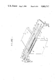
- FIG. 3 is a perspective view of the template constructed in accordance with the preferred embodiment of the present invention mounted on a jig designed to hold the wooden workpieces in place while being cut.
- FIG. 4 is a perspective view of a dovetail cutter.
- the template comprises an elongated template 1, preferably formed of a rigid material, having a first edge 4.
- the elongated template 1 has a longitudinally extending female cut groove slot 6, with a first end 7, a second end 8, a first edge 9, and a second edge 10; a longitudinally extending male cut tongue slot 11 having a first end 12, a second end 13, and a guide edge 14; and a longitudinally extending male cut indentation 15 having a first end 16 and a second end 17.
- the longitudinally extending female cut groove slot 6 is wider at its first end 7 than it is at its second end 8.
- Both first edge 9 and second edge 10 taper towards each other as they approach second end 8.
- this taper for each edge should amount to about 0.024 inches per foot.
- These tapers have been exaggerated in the drawing in order to demonstrate this aspect.
- This taper provides a tapered groove to be cut which allows for a tight fit between the workpieces, while still providing easy insertion of the male workpiece into the female workpiece.
- the taper in the edges 9 and 10 may be eliminated, if it is desired to cut just sliding dovetail joints, as opposed to tapered sliding dovetail joints.
- a workpiece 2 is positioned below template 1 so that the width of the workpiece is between the ends 7 and 8 of the female groove guide slot 6.
- the workpiece should be securely clamped to the template and the workpiece 2 should be perpendicular to first edge 4.
- a rotary dovetail cutter preferably a high speed router with a dovetail cutter (see FIG. 4,) is placed in the female groove slot 6 adjacent to the workpiece 2.
- the cutter may be placed in female groove slot 6 via template insertion gap 20. The depth of the cutter must be deep enough to allow the cutter to cut into the wood when the cutter is moved towards it.
- the cutter is then moved along the first edge 9 of female groove guide slot 6 from one end of of the guide slot to the other, and then moved along the second edge 10 of guide slot 6.
- the sliding dovetail female groove is cut as the cutter passes through the workpiece. If the template is constructed of a material which is not entirely rigid, it is important to not place undue pressure against the edges of the groove slot, or else the template could bend and cause an inaccurate cut.
- the guide edge 14 of longitudinally extending sliding dovetail male tongue guide slot 11 and longitudinally extending male tongue indentation 15 are both tapered so that they taper towards each other as they approach second end 13. Again, these tapers have been exaggerated in the drawing in order to fully demonstrate this aspect of the invention.
- the tapers of guide edge 14 and indentation 15 should both taper at the same rate as the longitudinally extending female cut groove slot 6.
- the tapers in both guide edge 14 and indentation 15 can be eliminated if it is desired to cut only sliding dovetails as opposed to tapered sliding dovetails.
- the traverse centerline (not shown) between guide edge 14 and indentation 15 should be parallel to first edge 4.
- the template should be constructed so that the width of the female groove guide slot 6 is proportional to the width of the portion of template 1 which lies between guide edge 14 of the male tongue guide slot 11 and indentation 15. Such a proportionality will ensure that the sizes of the female groove 27 and male tongue 26 cut in the workpieces will be of ideal dimensions, based upon a known width of the dovetail cutter blade 42, angle of the dovetail cutter, size of bearing 43 and depth of cut.
- a workpiece 3 is positioned below the template 1 so that the top edges 18 and 19 are visible through the top of the template but the middle of the top end is covered by the portion of the template between male tongue guide slot 11 and male tongue guide indentation 15.
- the workpiece should be positioned below the template the same distance from the first end 7 as the workpiece used to cut the female groove was placed from first end 7. This will ensure consistent widths of the tongue and groove.
- the workpiece should be securely clamped to the template.
- a rotary dovetail cutter preferably a high speed router with a dovetail bit (see FIG. 4,) is placed in the male tongue guide slot 11 adjacent to the wood.
- the cutter may be inserted into male tongue guide slot 11 via template insertion gap 21.
- the depth of the cutter must be deep enough to allow the cutter to cut into the workpiece when when the cutter is moved over it.
- the cutter shoud be set to a depth equal to the depth used to cut the sliding dovetail female groove, in order to provide the best fit between the workpieces.
- the cutter is then moved along the guide edge 14 of male tongue guide slot 11 from the first end 12 of the guide slot to the second end 13, cutting one side of the dovetail tongue.
- the cutter is then placed along the male tongue guide indentation 15 and moved along the indentation from the first end 16 to the second end 17 to complete the cut.
- Template 1 also has two angle brackets 22, each having guide slots 23, to allow template 1 to be attached to a work positioning structure when in use.
- FIG. 2 discloses a tapered sliding dovetail male tongue cut in a first piece of wood 3 and a tapered sliding dovetail female groove cut in a second piece of wood 2 using the present invention.
- the taper of the cut in each piece has been exaggerated to demonstrate this aspect of the invention.
- the narrow end 24 of the tongue in the first piece of wood 3 is inserted into the wide end 25 of the groove in the second piece of wood 2.
- the tongue 26 of the first piece of wood 3 is then inserted fully into the groove 27 of the second piece of wood 2, providing a tight fit of the dovetail joint.
- FIG. 3 discloses a combination of the template and dovetailing jig which may be used to secure wooden workpieces 2 and 3 for cutting using the present invention.
- the jig comprises a frame 28 having a horizontal work receiving surface 29 and a vertical work receiving surface 30.
- the frame houses two studs 47 which can accommodate the locating slots 23 in the angle brackets 22 of the template 1.
- Hand screws 31 allow the template 1 to be tightly secured to the frame 28.
- the locating slots 23 in the angle brackets 22 allow the template 1 to be positioned at various heights with respect to horizontal work receiving surface 29.
- Spacing washers 46 provide a gross adjustment between angle brackets 22 and frame 28 to allow the template 1 to be positioned at various distances with respect to vertical work receiving surface 30.
- Fine adjustment of the distance between template 1 and vertical working surface 30 may be made by adjusting locknuts 32, which are screwed onto studs 47. Such adjustments are convenient to allow the template 1 to accommodate varying thicknesses of workpieces when used with the dovetailing jig.
- Frame 28 also holds two cam clamp assemblies to hold the workpieces in place.
- Each clamp assembly is comprised of two eye bolts 33 which are secured to frame 28 by nuts 34.
- a cam clamp round 35 is positioned between the two eye bolts 33 and held in place by offset journals 36.
- a clamp flat 37 is placed between the clamp round 35 and the frame 28 to evenly distribute the pressure of the cam clamp against a workpiece.
- the clamp flat 37 is biased against the clamp round 35 via springs 38 which are placed around eye bolts 33.
- Each offset journal 36 is attached to a lever 39, which allows the clamp round 35 to be rotated to secure a workpiece between the cam clamp flat 37 and the horizontal or vertical work receiving surfaces, 29 and 30.
- Frame 28 also has holes 40, which allow frame 28 to be secured to a permanent location.
- FIG. 4 discloses a dovetail cutter which may be used to cut tapered sliding dovetail tongues and grooves as described above.
- the dovetail cutter includes a shank 41 for securement in the collet of a power tool, such as a hand-held power router, a dovetail cutter blade 42, a bearing 43, and a shank collar 44.
- Bearing 43 is held in place by shank collar 44, which is secured to shank 41 by a set screw 45.
Landscapes
- Life Sciences & Earth Sciences (AREA)
- Engineering & Computer Science (AREA)
- Wood Science & Technology (AREA)
- Mechanical Engineering (AREA)
- Forests & Forestry (AREA)
- Dovetailed Work, And Nailing Machines And Stapling Machines For Wood (AREA)
Abstract
Description
Claims (5)
Priority Applications (1)
| Application Number | Priority Date | Filing Date | Title |
|---|---|---|---|
| US06/735,828 US4603717A (en) | 1985-05-16 | 1985-05-16 | Sliding dovetail template |
Applications Claiming Priority (1)
| Application Number | Priority Date | Filing Date | Title |
|---|---|---|---|
| US06/735,828 US4603717A (en) | 1985-05-16 | 1985-05-16 | Sliding dovetail template |
Publications (1)
| Publication Number | Publication Date |
|---|---|
| US4603717A true US4603717A (en) | 1986-08-05 |
Family
ID=24957353
Family Applications (1)
| Application Number | Title | Priority Date | Filing Date |
|---|---|---|---|
| US06/735,828 Expired - Lifetime US4603717A (en) | 1985-05-16 | 1985-05-16 | Sliding dovetail template |
Country Status (1)
| Country | Link |
|---|---|
| US (1) | US4603717A (en) |
Cited By (26)
| Publication number | Priority date | Publication date | Assignee | Title |
|---|---|---|---|---|
| US4905745A (en) * | 1989-04-25 | 1990-03-06 | Jaeger Waldemar A | Woodcutting guide |
| GB2238752A (en) * | 1989-12-06 | 1991-06-12 | Edwin Bernard Froggatt | Dovetail joint formation |
| US5813807A (en) * | 1997-02-11 | 1998-09-29 | Rogers; Winston L. | Plunge router guide |
| US6032706A (en) * | 1999-02-10 | 2000-03-07 | Lear; Kevan F. | Woodworking jig |
| US20030196726A1 (en) * | 1999-06-18 | 2003-10-23 | Tucker Edwin C. | Router table joint making machine |
| US20040025362A1 (en) * | 2002-08-09 | 2004-02-12 | Allen Patrick J. | Tapered sliding dovetail tool and kit including such tool |
| US20040025363A1 (en) * | 2002-08-09 | 2004-02-12 | Allen Patrick J. | Tapered sliding dovetail tool and kit includings such tool |
| US20040194333A1 (en) * | 2002-08-09 | 2004-10-07 | Allen Patrick J. | Locking tapered sliding dovetail joint and tool and method for making the joint |
| US20040194332A1 (en) * | 2002-08-09 | 2004-10-07 | Allen Patrick J. | Locking tapered sliding dovetail joint and tool and method for making the joint |
| GB2427587A (en) * | 2005-06-30 | 2007-01-03 | John Barrington Parfitt | Jig system for complementary parts |
| USD559287S1 (en) | 2006-08-22 | 2008-01-08 | Black & Decker Corporation | Variable-spaced finger assembly |
| USD559875S1 (en) | 2006-08-22 | 2008-01-15 | Black & Decker Corporation | Half-blind router bit depth guide |
| USD560235S1 (en) | 2006-08-22 | 2008-01-22 | Black & Decker Corporation | Sliding tapered dovetail and fixed half-blind dovetail template |
| USD569882S1 (en) | 2006-08-22 | 2008-05-27 | Black & Decker Inc. | Miniature variable-spaced finger assembly |
| USD571836S1 (en) | 2006-08-22 | 2008-06-24 | Black & Decker Inc. | Box joint template |
| USD573615S1 (en) | 2006-08-22 | 2008-07-22 | Black & Decker Inc. | Dust collector |
| USD574864S1 (en) | 2006-08-22 | 2008-08-12 | Black & Decker Inc | Mortise and tenon assembly |
| USD575312S1 (en) | 2006-08-22 | 2008-08-19 | Black & Decker Inc. | Outrigger for a jig apparatus |
| USD577752S1 (en) | 2006-08-22 | 2008-09-30 | Black & Decker Inc. | Jig apparatus |
| US7434604B2 (en) | 2004-07-30 | 2008-10-14 | Black & Decker Inc. | Jig apparatus |
| US7455089B2 (en) | 2004-07-30 | 2008-11-25 | Black & Decker Inc. | Jig apparatus |
| US7703488B1 (en) | 2006-04-14 | 2010-04-27 | Douglas Lawrence M | Through dovetailing jig assembly |
| US7857020B2 (en) | 2004-07-30 | 2010-12-28 | Black & Decker Inc. | Jig apparatus |
| US8915039B1 (en) | 2013-06-05 | 2014-12-23 | Vasile C. OROS | Solid-wood rigid block assemblies |
| US9988906B2 (en) | 2013-02-08 | 2018-06-05 | General Electric Company | Turbomachine rotor blade milling machine system and method of field repairing a turbomachine rotor blade |
| US20230294272A1 (en) * | 2022-03-16 | 2023-09-21 | Devon James Perlenfein | Template for forming faucet assembly holes in a countertop |
Citations (3)
| Publication number | Priority date | Publication date | Assignee | Title |
|---|---|---|---|---|
| US3376650A (en) * | 1966-02-11 | 1968-04-09 | George M. Cook | Template |
| US3878875A (en) * | 1972-07-26 | 1975-04-22 | Vermont American Corp | Dovetail fixture |
| US4479523A (en) * | 1982-09-30 | 1984-10-30 | Dale Peterson | Mortise and tenon jig |
-
1985
- 1985-05-16 US US06/735,828 patent/US4603717A/en not_active Expired - Lifetime
Patent Citations (3)
| Publication number | Priority date | Publication date | Assignee | Title |
|---|---|---|---|---|
| US3376650A (en) * | 1966-02-11 | 1968-04-09 | George M. Cook | Template |
| US3878875A (en) * | 1972-07-26 | 1975-04-22 | Vermont American Corp | Dovetail fixture |
| US4479523A (en) * | 1982-09-30 | 1984-10-30 | Dale Peterson | Mortise and tenon jig |
Cited By (36)
| Publication number | Priority date | Publication date | Assignee | Title |
|---|---|---|---|---|
| US4905745A (en) * | 1989-04-25 | 1990-03-06 | Jaeger Waldemar A | Woodcutting guide |
| GB2238752A (en) * | 1989-12-06 | 1991-06-12 | Edwin Bernard Froggatt | Dovetail joint formation |
| GB2238752B (en) * | 1989-12-06 | 1993-10-06 | Edwin Bernard Froggatt | Dovetail joint formation |
| US5813807A (en) * | 1997-02-11 | 1998-09-29 | Rogers; Winston L. | Plunge router guide |
| US6032706A (en) * | 1999-02-10 | 2000-03-07 | Lear; Kevan F. | Woodworking jig |
| AU756076B2 (en) * | 1999-02-10 | 2003-01-02 | Kevan Lear | Woodworking jig |
| US20030196726A1 (en) * | 1999-06-18 | 2003-10-23 | Tucker Edwin C. | Router table joint making machine |
| US20040194333A1 (en) * | 2002-08-09 | 2004-10-07 | Allen Patrick J. | Locking tapered sliding dovetail joint and tool and method for making the joint |
| US6898863B2 (en) | 2002-08-09 | 2005-05-31 | Patrick J. Allen | Locking tapered sliding dovetail joint and tool and method for making the joint |
| US6732444B2 (en) | 2002-08-09 | 2004-05-11 | Patrick J. Allen | Tapered sliding dovetail tool and kit including such tool |
| US20040025362A1 (en) * | 2002-08-09 | 2004-02-12 | Allen Patrick J. | Tapered sliding dovetail tool and kit including such tool |
| US20040194332A1 (en) * | 2002-08-09 | 2004-10-07 | Allen Patrick J. | Locking tapered sliding dovetail joint and tool and method for making the joint |
| US6802134B2 (en) | 2002-08-09 | 2004-10-12 | Patrick J. Allen | Tapered sliding dovetail tool and kit including such tool |
| US6898864B2 (en) | 2002-08-09 | 2005-05-31 | Patrick J. Allen | Locking tapered sliding dovetail joint and tool and method for making the joint |
| US20040025363A1 (en) * | 2002-08-09 | 2004-02-12 | Allen Patrick J. | Tapered sliding dovetail tool and kit includings such tool |
| US7857020B2 (en) | 2004-07-30 | 2010-12-28 | Black & Decker Inc. | Jig apparatus |
| US7819146B2 (en) | 2004-07-30 | 2010-10-26 | Black & Decker Inc. | Jig apparatus |
| US7717145B2 (en) | 2004-07-30 | 2010-05-18 | Black & Decker Inc. | Router support for a jig apparatus |
| US7434604B2 (en) | 2004-07-30 | 2008-10-14 | Black & Decker Inc. | Jig apparatus |
| US7455089B2 (en) | 2004-07-30 | 2008-11-25 | Black & Decker Inc. | Jig apparatus |
| GB2427587A (en) * | 2005-06-30 | 2007-01-03 | John Barrington Parfitt | Jig system for complementary parts |
| US7703488B1 (en) | 2006-04-14 | 2010-04-27 | Douglas Lawrence M | Through dovetailing jig assembly |
| US7931059B1 (en) | 2006-04-14 | 2011-04-26 | Douglas Lawrence M | Through dovetailing jig assembly |
| USD573615S1 (en) | 2006-08-22 | 2008-07-22 | Black & Decker Inc. | Dust collector |
| USD577752S1 (en) | 2006-08-22 | 2008-09-30 | Black & Decker Inc. | Jig apparatus |
| USD574864S1 (en) | 2006-08-22 | 2008-08-12 | Black & Decker Inc | Mortise and tenon assembly |
| USD571836S1 (en) | 2006-08-22 | 2008-06-24 | Black & Decker Inc. | Box joint template |
| USD569882S1 (en) | 2006-08-22 | 2008-05-27 | Black & Decker Inc. | Miniature variable-spaced finger assembly |
| USD560235S1 (en) | 2006-08-22 | 2008-01-22 | Black & Decker Corporation | Sliding tapered dovetail and fixed half-blind dovetail template |
| USD559875S1 (en) | 2006-08-22 | 2008-01-15 | Black & Decker Corporation | Half-blind router bit depth guide |
| USD559287S1 (en) | 2006-08-22 | 2008-01-08 | Black & Decker Corporation | Variable-spaced finger assembly |
| USD575312S1 (en) | 2006-08-22 | 2008-08-19 | Black & Decker Inc. | Outrigger for a jig apparatus |
| US9988906B2 (en) | 2013-02-08 | 2018-06-05 | General Electric Company | Turbomachine rotor blade milling machine system and method of field repairing a turbomachine rotor blade |
| US8915039B1 (en) | 2013-06-05 | 2014-12-23 | Vasile C. OROS | Solid-wood rigid block assemblies |
| US20230294272A1 (en) * | 2022-03-16 | 2023-09-21 | Devon James Perlenfein | Template for forming faucet assembly holes in a countertop |
| US12358125B2 (en) * | 2022-03-16 | 2025-07-15 | Devon James Perlenfein | Template for forming faucet assembly holes in a countertop |
Similar Documents
| Publication | Publication Date | Title |
|---|---|---|
| US4603717A (en) | Sliding dovetail template | |
| US4479523A (en) | Mortise and tenon jig | |
| US5890524A (en) | Router table sled | |
| US7621206B2 (en) | Multi-function woodworking guide | |
| US5018562A (en) | Power tool fence system | |
| US4630657A (en) | Versatile router guide apparatus | |
| US4168730A (en) | Apparatus and methods for forming dovetail joints | |
| CA2155467C (en) | Saw guide | |
| US5816300A (en) | Woodworking jig | |
| US20030233926A1 (en) | Multi-function woodworking system | |
| US4793604A (en) | Universal precision positioning jig | |
| US5931208A (en) | Jig for cutting dovetail joints | |
| US4300755A (en) | Miter box construction with clamp means | |
| US4454793A (en) | Attachment for a miter gauge | |
| US5042346A (en) | Apparatus for fabricating accurate mitered corners | |
| US4074736A (en) | Milling gauge | |
| US4867425A (en) | Portable guide fence for hand held power saws | |
| WO1994026483A1 (en) | Method and means for making mitre joints | |
| US5513437A (en) | Dovetail tenon offset caliper and dovetail tenon construction method | |
| US20030233925A1 (en) | Multi-function woodworking adapter | |
| US20030145705A1 (en) | Fence | |
| US6530302B1 (en) | Cabinetmaking system | |
| US7931059B1 (en) | Through dovetailing jig assembly | |
| US5493789A (en) | Miter gauge calibrator | |
| US11780111B1 (en) | Tool and system for forming multiple woodworking joints |
Legal Events
| Date | Code | Title | Description |
|---|---|---|---|
| STCF | Information on status: patent grant |
Free format text: PATENTED CASE |
|
| AS | Assignment |
Owner name: PORTER-CABLE CORPORATION, P. O. BOX 2468, JACKSON, Free format text: ASSIGNMENT OF ASSIGNORS INTEREST.;ASSIGNOR:THOMAS, DONALD E.;REEL/FRAME:004908/0838 Effective date: 19880602 Owner name: PORTER-CABLE CORPORATION,TENNESSEE Free format text: ASSIGNMENT OF ASSIGNORS INTEREST;ASSIGNOR:THOMAS, DONALD E.;REEL/FRAME:004908/0838 Effective date: 19880602 |
|
| FEPP | Fee payment procedure |
Free format text: PAYOR NUMBER ASSIGNED (ORIGINAL EVENT CODE: ASPN); ENTITY STATUS OF PATENT OWNER: LARGE ENTITY |
|
| FEPP | Fee payment procedure |
Free format text: PAT HLDR NO LONGER CLAIMS SMALL ENT STAT AS INDIV INVENTOR (ORIGINAL EVENT CODE: LSM1); ENTITY STATUS OF PATENT OWNER: LARGE ENTITY |
|
| FPAY | Fee payment |
Year of fee payment: 4 |
|
| FPAY | Fee payment |
Year of fee payment: 8 |
|
| FPAY | Fee payment |
Year of fee payment: 12 |