US459857A - Mine-timbers - Google Patents
Mine-timbers Download PDFInfo
- Publication number
- US459857A US459857A US459857DA US459857A US 459857 A US459857 A US 459857A US 459857D A US459857D A US 459857DA US 459857 A US459857 A US 459857A
- Authority
- US
- United States
- Prior art keywords
- tenon
- beams
- post
- cap
- horizontal
- Prior art date
- Legal status (The legal status is an assumption and is not a legal conclusion. Google has not performed a legal analysis and makes no representation as to the accuracy of the status listed.)
- Expired - Lifetime
Links
- 238000006073 displacement reaction Methods 0.000 description 3
- 230000015572 biosynthetic process Effects 0.000 description 2
- 230000000284 resting effect Effects 0.000 description 2
- 238000009412 basement excavation Methods 0.000 description 1
- 238000010276 construction Methods 0.000 description 1
- 229910052500 inorganic mineral Inorganic materials 0.000 description 1
- 239000011707 mineral Substances 0.000 description 1
Images

Classifications
-
- E—FIXED CONSTRUCTIONS
- E04—BUILDING
- E04B—GENERAL BUILDING CONSTRUCTIONS; WALLS, e.g. PARTITIONS; ROOFS; FLOORS; CEILINGS; INSULATION OR OTHER PROTECTION OF BUILDINGS
- E04B1/00—Constructions in general; Structures which are not restricted either to walls, e.g. partitions, or floors or ceilings or roofs
- E04B1/18—Structures comprising elongated load-supporting parts, e.g. columns, girders, skeletons
- E04B1/24—Structures comprising elongated load-supporting parts, e.g. columns, girders, skeletons the supporting parts consisting of metal
- E04B1/2403—Connection details of the elongated load-supporting parts
-
- Y—GENERAL TAGGING OF NEW TECHNOLOGICAL DEVELOPMENTS; GENERAL TAGGING OF CROSS-SECTIONAL TECHNOLOGIES SPANNING OVER SEVERAL SECTIONS OF THE IPC; TECHNICAL SUBJECTS COVERED BY FORMER USPC CROSS-REFERENCE ART COLLECTIONS [XRACs] AND DIGESTS
- Y10—TECHNICAL SUBJECTS COVERED BY FORMER USPC
- Y10T—TECHNICAL SUBJECTS COVERED BY FORMER US CLASSIFICATION
- Y10T403/00—Joints and connections
- Y10T403/34—Branched
- Y10T403/341—Three or more radiating members
- Y10T403/344—Plural pairs of axially aligned members
Definitions
- the purpose of this invention is to provide an improved system of mine-timbers-that is, timbers to stay the walls of excavations in mines in which the formation through which passages are cut or from which mineral is removed is not of sufficiently firm and rigid character to be self-supporting.
- the cost of timbering in such formation is very great, and I aim to provide a safe construction at less cost and adapted to be put into place more promptly and rapidly than has heretofore been done.
- Figure 1 is a-vertical section transversely across a drift or room which has been timbered according to my invention.
- Fig. 2 is a horizontal section of the same.
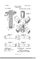
- Fig. 3 is an enlarged detail plan of one of the joints which constitute the distinguishing feature of my invention.
- Fig. 4 is a vertical section through such joint at the line 4 4 on Fig. 3, but showing an additional post extending up from the joint.
- Fig. 5 is a perspective of all the parts of such joint dissected,but in the same relation to each other as in the compacted joint.
- Fig. 6 is a plan of the cap-beams.
- Fig. 7 is a side elevation of the same.
- Fig. S is a plan of one of the bracebeams.
- Fig. 9 is a side elevation of the same.
- A is the foot-block or sill, which rests on the floor of the drift or room. It has a square socket c, which receives the tenons of the lower end of the lowest of the posts B.
- Each post has at its upper end the square tenon b and the smaller square terminal tenon b2, whose sides are at angles of forty-tive degrees to the sides of the tenon b.
- cap-beams which in the case of a drift o1 ⁇ narrow room may abut endwise against the head and foot walls of such drift or room.
- These cap-beams are each rabbeted all around the end which abuts on the post, leaving a tenon c as wide the post, the length of the tenon b2 being half the transverse dimension of the post-tenon b.
- the post is further rabbeted at the vertical side edges back of the tenon c, reducing its Width to that of the tenon b and forming a subsidiarjr tenon c.
- the tenon c is provided at the end with the V-shaped or right-angular notch c2, which is adapted to receive cornerwise half the tenon b2, which just tits it, so that taking together the two beams C, which abut from opposite directions on the post, their notches c2 form a square openin g which just receives the post-tenon b2.
- D D are two longitudinal brace-beams, which abut end to end from opposite directions on the post B. They are each rabbeted all around the end to form the tenon d, whose ⁇ length is the difference between the equal transverse dimensions of the post-tenon b and the diagonal dimension of the post-tenon b2, and Whose horizontal width is equal to said equal diagonal dimensions of the tenon o', its vertical dimension being double the length of the post-tenon b2 and equal to the vertical width of the tenon c.
- the beams D are each further rabbeted at the vertical side edges of the ends, forming a subsidiary tenon d or base for the tenon d, said subsidiary tenon being in vertical width the full thickness of the beams D and in horizontal Width equal to the width of the posttenon plus twice the length of the subsidiary tenon c of the cap-beam C.
- the lower post B When assembled as illustrated in the drawings, the lower post B is stepped in the footblock or sill A.
- the horizontal beams O and D obtain support upon the shoulder B around the tenon b', and in addition to this support the beam C has its tenon c resting on the shoulder B2, Which extends around the tenon b2, and the beam D has its tenon d resting on so much of the same shoulder as is not occupied by the tenon c.
- the right-angle notches c2 of the tenon c embrace the post-tenon b2, and are in turn bound transversely between the square ends of the tenons d d.
- the shoulder C at the base of the tenon c and the shoulder D at the base of the tenon d now bound a socket whose bottom is formed by the end of the tenon b2 and whose shape is that of the combined tenons b b2.
- This socket as the diagonal dimension of the tenon b2 of is adapted to receive the lower end tenons b Back of the tenon d IOO b2 of the next post above the horizontal system of beams C C D D, and said socket is identical in form and dimension with the downwardly-facing cavity formed by the horizontal beams which receive the upper end tenons b h2 of the lower posts; so that the horizontal beams C and D may be laid either side up inditerently.
- the V-shaped notches at the ends of the transverse horizon tal beams enable said beams not only to prevent the post being displaced transversely, but also prevent displacement in every other horizontal direction,
- a caving' tendency of the walls is liable to cause the ends of the transverse beams to slip olf the posts, or, slipping slightly in opposite directions, to twist the post around and so dislodge the beams from the post and permit collapse of the structure;
- the arrangement of the shoulders at the base of the several tenons both on the posts and on the horizontal beams causes pressure in any direction to bind the joint tighter, and particularly the shoulders at the base of the notched tenons b', abutting squarely-that is, at right angles to the length of the cap beams-against corresponding shoulders of the posts, prevent the endwise pressure of the cap-beams from splitting the latter, as might otherwise occur from the wedge-like action of the tenons Z
- a system of mine-timbers comprising, in combination, substantially as set forth, upright posts and horizontal cap-beams, theposts having end tenons and the cap-beams being notched at their ends to receive said tenons and having' l'ightangular transverse rabbets on their horizontal faces back of their notches to form vertical shoulders at right angles to the length of the cap-beams and which bear against the posts respectively above and below the tenons, whichl are engaged in said end notches, substantially as set forth.
- a system of mine-timbers comprising, in combination, substantially as set forth, upright posts and horizontal cap-beams, the posts having angular end tenons whose faces are oblique to the length of the cap-beams and the cap-beams being transversely rabbeted to form vertical shoulders at right angles to the length of said beams and notched at the ends to receive the angles of said post-tenons, whereby the transverse vertical shoulders transmit the end-thrust of the cap-beams squarely against the posts, and the notched ends engaging the tenons prevent lateral displacement.
- a system 4of mine-timbers comprising, in combination, substantially as set forth, upright posts and horizontal cap and brace beams, the posts being rabbeted at theirends to form horizontal shoulders on all four sides, and a tenen bounded by such shoulders and having its faces at right angles to the length of the horizontal beams, said tenen being further rabbeted to form a second tenon protruding from the end of the first tenon and having faces oblique to the faces of the first tenon, the horizontal cap-beams being lodged upon two of the opposite horizontal shoulders of the post and rabbeted at their side edges and the brace-beams extending transversely to the direction of the cap-beams and lodged upon the other two opposite horizontal shoulders of the post and entering the lateral rabbets of the cap-beams and stopped bythe longitudinal vertical shoulders of said rabbets, the cap beams being notched at their ends and embracing in such notches the obliquely-laced terminal ten
Landscapes
- Engineering & Computer Science (AREA)
- Architecture (AREA)
- Physics & Mathematics (AREA)
- Electromagnetism (AREA)
- Civil Engineering (AREA)
- Structural Engineering (AREA)
- Joining Of Building Structures In Genera (AREA)
Description
2 Sheets-Sheet 1.
Patented Sept. 22, 1891.
J. OLCO'TT. MINE TIMBER.
\\ \\\\3L\\L\ u umn efe-1- (No Model.)
Fg@ e.
(No Model.) 2 Sheets-Sheet 2. W. J. OLCOTT.
MINE TIMBER. N0- 459,85? Patented Sept. 22, 1891.
C e, Fd@ Z 6' /Znecwe [avez/afar UNITED STATES yPATENT OEEICE.
IVILLIAM J. OLCOTT, OF BESSl-EMER, MICHIGAN.
MINE-TI MBERS.
SPECIFICATION formingpart of Letters Patent No. 459,857, dated September 22, 1891.
Application led April 2'7,l 1891. Serial No. 390,604. (No model.)
To all whom, it may concern:
Be it known that I, WILLIAM J. OLCOTT, a cltlzen of the United States, residing at Bessemer, county of Gogebic, State of Michigan, have invented certain new and usefullmprovements in Mine-Timbers, which are fully set forth in the following specification, reference being had to the accompanying drawings, forming a part thereof.
The purpose of this invention is to provide an improved system of mine-timbers-that is, timbers to stay the walls of excavations in mines in which the formation through which passages are cut or from which mineral is removed is not of sufficiently firm and rigid character to be self-supporting. The cost of timbering in such formation is very great, and I aim to provide a safe construction at less cost and adapted to be put into place more promptly and rapidly than has heretofore been done.
In the drawings, Figure 1 is a-vertical section transversely across a drift or room which has been timbered according to my invention. Fig. 2 is a horizontal section of the same. Fig. 3 is an enlarged detail plan of one of the joints which constitute the distinguishing feature of my invention. Fig. 4 is a vertical section through such joint at the line 4 4 on Fig. 3, but showing an additional post extending up from the joint. Fig. 5 is a perspective of all the parts of such joint dissected,but in the same relation to each other as in the compacted joint. Fig. 6 is a plan of the cap-beams. Fig. 7 is a side elevation of the same. Fig. S is a plan of one of the bracebeams. Fig. 9 is a side elevation of the same.
A is the foot-block or sill, which rests on the floor of the drift or room. It has a square socket c, which receives the tenons of the lower end of the lowest of the posts B. Each post has at its upper end the square tenon b and the smaller square terminal tenon b2, whose sides are at angles of forty-tive degrees to the sides of the tenon b.
C C are transverse horizontal cap-beams, which in the case of a drift o1` narrow room may abut endwise against the head and foot walls of such drift or room. These cap-beams are each rabbeted all around the end which abuts on the post, leaving a tenon c as wide the post, the length of the tenon b2 being half the transverse dimension of the post-tenon b. The post is further rabbeted at the vertical side edges back of the tenon c, reducing its Width to that of the tenon b and forming a subsidiarjr tenon c. The tenon c is provided at the end with the V-shaped or right-angular notch c2, which is adapted to receive cornerwise half the tenon b2, which just tits it, so that taking together the two beams C, which abut from opposite directions on the post, their notches c2 form a square openin g which just receives the post-tenon b2.
D D are two longitudinal brace-beams, which abut end to end from opposite directions on the post B. They are each rabbeted all around the end to form the tenon d, whose` length is the difference between the equal transverse dimensions of the post-tenon b and the diagonal dimension of the post-tenon b2, and Whose horizontal width is equal to said equal diagonal dimensions of the tenon o', its vertical dimension being double the length of the post-tenon b2 and equal to the vertical width of the tenon c. the beams D are each further rabbeted at the vertical side edges of the ends, forming a subsidiary tenon d or base for the tenon d, said subsidiary tenon being in vertical width the full thickness of the beams D and in horizontal Width equal to the width of the posttenon plus twice the length of the subsidiary tenon c of the cap-beam C.
When assembled as illustrated in the drawings, the lower post B is stepped in the footblock or sill A. The horizontal beams O and D obtain support upon the shoulder B around the tenon b', and in addition to this support the beam C has its tenon c resting on the shoulder B2, Which extends around the tenon b2, and the beam D has its tenon d resting on so much of the same shoulder as is not occupied by the tenon c. The right-angle notches c2 of the tenon c embrace the post-tenon b2, and are in turn bound transversely between the square ends of the tenons d d. The shoulder C at the base of the tenon c and the shoulder D at the base of the tenon d now bound a socket whose bottom is formed by the end of the tenon b2 and whose shape is that of the combined tenons b b2. This socket as the diagonal dimension of the tenon b2 of is adapted to receive the lower end tenons b Back of the tenon d IOO b2 of the next post above the horizontal system of beams C C D D, and said socket is identical in form and dimension with the downwardly-facing cavity formed by the horizontal beams which receive the upper end tenons b h2 of the lower posts; so that the horizontal beams C and D may be laid either side up inditerently. The advantages of this joint are that the V-shaped notches at the ends of the transverse horizon tal beams enable said beams not only to prevent the post being displaced transversely, but also prevent displacement in every other horizontal direction, Whereas in the absence of such a provision a caving' tendency of the walls is liable to cause the ends of the transverse beams to slip olf the posts, or, slipping slightly in opposite directions, to twist the post around and so dislodge the beams from the post and permit collapse of the structure; also, the arrangement of the shoulders at the base of the several tenons both on the posts and on the horizontal beams causes pressure in any direction to bind the joint tighter, and particularly the shoulders at the base of the notched tenons b', abutting squarely-that is, at right angles to the length of the cap beams-against corresponding shoulders of the posts, prevent the endwise pressure of the cap-beams from splitting the latter, as might otherwise occur from the wedge-like action of the tenons Z22 in the notches c2.
These timbers can be very rapidly asselnn bled and are held together simply by the pressure of the Walls, which it is their function to withstand, and the entire system of such timbers in any transverse section of a drift or room will be rendered rigid and secure by merely wedgin g the extreme beams against the lateral walls and the top post against the roof without being obliged to place dependence upon spikes or pins or similar fastenings.
I claiml. A system of mine-timbers, comprising, in combination, substantially as set forth, upright posts and horizontal cap-beams, theposts having end tenons and the cap-beams being notched at their ends to receive said tenons and having' l'ightangular transverse rabbets on their horizontal faces back of their notches to form vertical shoulders at right angles to the length of the cap-beams and which bear against the posts respectively above and below the tenons, whichl are engaged in said end notches, substantially as set forth.
2. A system of mine-timbers, comprising, in combination, substantially as set forth, upright posts and horizontal cap-beams, the posts having angular end tenons whose faces are oblique to the length of the cap-beams and the cap-beams being transversely rabbeted to form vertical shoulders at right angles to the length of said beams and notched at the ends to receive the angles of said post-tenons, whereby the transverse vertical shoulders transmit the end-thrust of the cap-beams squarely against the posts, and the notched ends engaging the tenons prevent lateral displacement.
3. In combination with the post having two end tenons, the second protruding from the end of the first, horizontal cap-beams having right-angular transverse rabbets to form vertical shoulders at right angles to the length of the capbeams and which abut against two opposite faces of the first tenon, said capbeams being notched at the ends to receive the angles of the second tenon, substantially as set forth.
4. In combination with the post having two end tenons, the second protruding from the end of the first, the faces of second tenon being oblique to the faces of the firsttenon, her1- zontal cap-beams rabbeted to form shoulders, which abut against two opposite faces of the rst tenon and notched at the ends to receive the angles of the second tenon, substantially as set forth.
5. A system 4of mine-timbers, comprising, in combination, substantially as set forth, upright posts and horizontal cap and brace beams, the posts being rabbeted at theirends to form horizontal shoulders on all four sides, and a tenen bounded by such shoulders and having its faces at right angles to the length of the horizontal beams, said tenen being further rabbeted to form a second tenon protruding from the end of the first tenon and having faces oblique to the faces of the first tenon, the horizontal cap-beams being lodged upon two of the opposite horizontal shoulders of the post and rabbeted at their side edges and the brace-beams extending transversely to the direction of the cap-beams and lodged upon the other two opposite horizontal shoulders of the post and entering the lateral rabbets of the cap-beams and stopped bythe longitudinal vertical shoulders of said rabbets, the cap beams being notched at their ends and embracing in such notches the obliquely-laced terminal tenon of the post, whereby the endthrust of the cap-beams is transmitted by the transverse vertical shoulders of their lateral rabbets laterally against the bracebeams Where the latter enter said rabbets, and the obliquely-faced post-tenon prevents lateral displacement of the capebeams and is relieved from the principal end-thrust to prevent it splitting the cap-beams.
In testimony whereof l have hereunto set IOO ITO
my hand, at Bessemer, Michigan, this 23d day of April, 1301.
W. J. OLCOTT. lVitnesscs:
F. R. HARVEY, Guo. II. STRONG.
Publications (1)
| Publication Number | Publication Date |
|---|---|
| US459857A true US459857A (en) | 1891-09-22 |
Family
ID=2528732
Family Applications (1)
| Application Number | Title | Priority Date | Filing Date |
|---|---|---|---|
| US459857D Expired - Lifetime US459857A (en) | Mine-timbers |
Country Status (1)
| Country | Link |
|---|---|
| US (1) | US459857A (en) |
Cited By (2)
| Publication number | Priority date | Publication date | Assignee | Title |
|---|---|---|---|---|
| US2505902A (en) * | 1943-11-29 | 1950-05-02 | Madger Arthur Wakefield | Wall structure embodying panel units |
| US5318387A (en) * | 1991-03-13 | 1994-06-07 | H L & H Timber Products (Proprietary) Limited | Yieldable load support |
-
0
- US US459857D patent/US459857A/en not_active Expired - Lifetime
Cited By (2)
| Publication number | Priority date | Publication date | Assignee | Title |
|---|---|---|---|---|
| US2505902A (en) * | 1943-11-29 | 1950-05-02 | Madger Arthur Wakefield | Wall structure embodying panel units |
| US5318387A (en) * | 1991-03-13 | 1994-06-07 | H L & H Timber Products (Proprietary) Limited | Yieldable load support |
Similar Documents
| Publication | Publication Date | Title |
|---|---|---|
| US4867598A (en) | Tapered dovetail mortise and tenon joint structure | |
| NO153537B (en) | RELATIONSHIP BETWEEN A BEARER AND A BUILDING PART. | |
| GB2567030A (en) | A unit for defining a recess for a joint | |
| US2886857A (en) | Wooden beam constructions | |
| CA2622773A1 (en) | Modular log building construction | |
| US1248070A (en) | Reinforced-concrete cribbing. | |
| US2495966A (en) | Joint between structural members of buildings | |
| US1994A (en) | Manner of fastening and gombining ti-ie truss-frames of bblidges | |
| US1571092A (en) | Connection for building columns | |
| US20060002770A1 (en) | Lite mine roof support crib and method | |
| US123219A (en) | Improvement in wood-pavements | |
| JP2003176585A (en) | Wooden building wall structure | |
| US20020139077A1 (en) | Pyramid crib blocks | |
| US511249A (en) | Hollow-tile girder and wall | |
| US2505903A (en) | Paneled wall structure | |
| JP4819783B2 (en) | Fireproof / seismic wall with wooden small thick plate and its construction method | |
| US2035050A (en) | Concrete cribbing | |
| US429439A (en) | Timber structure for mines | |
| US1708162A (en) | Building construction | |
| AU2016244181A1 (en) | Improvements in or in relation to mine roof cribs and associated joiners | |
| US2980216A (en) | Constructional metalwork | |
| RU131395U1 (en) | CORNER JOINT FOR THE HOUSE IN THE FOUR-SIDED LOCKING Groove (IN “OBLO”) | |
| US1031046A (en) | Concrete construction. | |
| US10819A (en) | John p | |
| US2847847A (en) | Interlocked blocks |