US4593603A - Asymmetrically accelerated vibrator for feeding materials - Google Patents
Asymmetrically accelerated vibrator for feeding materials Download PDFInfo
- Publication number
- US4593603A US4593603A US06/628,769 US62876984A US4593603A US 4593603 A US4593603 A US 4593603A US 62876984 A US62876984 A US 62876984A US 4593603 A US4593603 A US 4593603A
- Authority
- US
- United States
- Prior art keywords
- piston
- recess
- valve
- air
- compressed air
- Prior art date
- Legal status (The legal status is an assumption and is not a legal conclusion. Google has not performed a legal analysis and makes no representation as to the accuracy of the status listed.)
- Expired - Lifetime
Links
- 239000000463 material Substances 0.000 title claims abstract description 45
- 230000033001 locomotion Effects 0.000 claims abstract description 42
- 238000000034 method Methods 0.000 claims description 10
- 238000013016 damping Methods 0.000 claims description 4
- XAGFODPZIPBFFR-UHFFFAOYSA-N aluminium Chemical compound [Al] XAGFODPZIPBFFR-UHFFFAOYSA-N 0.000 claims description 3
- 229910052782 aluminium Inorganic materials 0.000 claims description 3
- 230000002250 progressing effect Effects 0.000 claims description 2
- 238000009429 electrical wiring Methods 0.000 abstract 1
- 238000012423 maintenance Methods 0.000 abstract 1
- 238000010276 construction Methods 0.000 description 10
- 230000001133 acceleration Effects 0.000 description 7
- 230000003068 static effect Effects 0.000 description 4
- 238000010586 diagram Methods 0.000 description 2
- 229910001018 Cast iron Inorganic materials 0.000 description 1
- 239000004809 Teflon Substances 0.000 description 1
- 229920006362 Teflon® Polymers 0.000 description 1
- 230000003213 activating effect Effects 0.000 description 1
- 230000036461 convulsion Effects 0.000 description 1
- 230000000977 initiatory effect Effects 0.000 description 1
- 238000012986 modification Methods 0.000 description 1
- 230000004048 modification Effects 0.000 description 1
- 239000002245 particle Substances 0.000 description 1
- 239000004033 plastic Substances 0.000 description 1
Images


Classifications
-
- B—PERFORMING OPERATIONS; TRANSPORTING
- B06—GENERATING OR TRANSMITTING MECHANICAL VIBRATIONS IN GENERAL
- B06B—METHODS OR APPARATUS FOR GENERATING OR TRANSMITTING MECHANICAL VIBRATIONS OF INFRASONIC, SONIC, OR ULTRASONIC FREQUENCY, e.g. FOR PERFORMING MECHANICAL WORK IN GENERAL
- B06B1/00—Methods or apparatus for generating mechanical vibrations of infrasonic, sonic, or ultrasonic frequency
- B06B1/18—Methods or apparatus for generating mechanical vibrations of infrasonic, sonic, or ultrasonic frequency wherein the vibrator is actuated by pressure fluid
- B06B1/183—Methods or apparatus for generating mechanical vibrations of infrasonic, sonic, or ultrasonic frequency wherein the vibrator is actuated by pressure fluid operating with reciprocating masses
-
- Y—GENERAL TAGGING OF NEW TECHNOLOGICAL DEVELOPMENTS; GENERAL TAGGING OF CROSS-SECTIONAL TECHNOLOGIES SPANNING OVER SEVERAL SECTIONS OF THE IPC; TECHNICAL SUBJECTS COVERED BY FORMER USPC CROSS-REFERENCE ART COLLECTIONS [XRACs] AND DIGESTS
- Y10—TECHNICAL SUBJECTS COVERED BY FORMER USPC
- Y10S—TECHNICAL SUBJECTS COVERED BY FORMER USPC CROSS-REFERENCE ART COLLECTIONS [XRACs] AND DIGESTS
- Y10S209/00—Classifying, separating, and assorting solids
- Y10S209/92—Vibratory feed conveyor
Definitions
- the present invention provides an asymmetrically accelerated vibrator for feeding materials which uses pistons activated by compressed air.
- Conventional air tools include impact tools such as hammers and other devices to provide reciprocal motion. Such reciprocal motions are frequently such that the forward and the backward motion are more or less symmetrical. It has been desirable to have units where the forward and the backward motion are different such that the difference between the friction of initiation and the sliding friction can be used to move materials depending on the cycle of the strokes. Furthermore, air driven tools in most cases contained springs, which present a service problem since they are subject to wear and breakage.
- the present invention provides an asymmetrically accelerated vibrator for feeding materials which comprises a compressed air feed at a casing, a first piston having a relatively small diameter and disposed in a first chamber of the casing, an air feed connecting the feed line to the chamber of the first piston, a second larger diameter piston disposed in a second recess of the casing and running in a direction parallel to the first piston, a mechanical connection between the first and second piston such that those pistons move uniformly, a support bar attached to the face of the second piston directed into the second recess, a valve member disposed in front of the second piston inside of the second recess and adapted to be pulled outward by the bar in case the second piston moves outward and adapted to be pushed inward by the head of the second piston, an air feed connected to the feed line to the inside area in front of the second piston and closable by the valve member in case the piston moves outwardly, which feed line opens when the head of the second piston presses against the valve member, and an exhaust line for the second rece
- Graduated air feeds can connect the feed line to the recess of the first piston such that the amount of air streaming from the feed line to the piston area is initially smaller and increases with outward motion of the first piston.
- a valve can be associated with the air feed connecting the feed line to the recess of the first piston for allowing an increased discharge flow from the first recess when the first piston moves into the recess.
- the exhaust line for the second recess can be disposed further inward into the recess relative to the feed line input for the compressed air.
- a springing and damping piece can be disposed between the second piston and the valve member disposed in front of the second piston for cushioning the force engagements between the support bar and the valve.
- the valve member disposed in front of the second piston can have openings such that the compressed air can fill the recess ahead of the second piston.
- An air inlet valve can be furnished for the air intake of the second recess wherein the valve disposed in front of the second piston is a valve actuator, which can open the air inlet valve when the valve moves deep into the recess.
- a bevel can be provided at the front cylinder of the valve member disposed in front of the second piston to allow engagement of a pin of the air inlet valve when the valve member moves into the piston, and a smaller diameter section of the valve member following the bevel to retain the air inlet valve in an open position while the valve is deep in the second recess.
- a small diameter bore in the casing can provide the vent for the exhaust air.
- a control piston can slide in the small diameter bore for controlling the exhaust air opening of the second recess.
- An exhaust air path can run from the second recess to a longitudinal slot in the wall of the small diameter bore disposed about the area of the end of the piston for allowing the air exhaust path to become larger as the second piston moves further into the second recess.
- the casing can be made of aluminum.
- the first piston and the second piston can be sealed against the respective recess wall with an O-ring.
- a method for converting compressed air power into an asymmetrically accelerated vibration for feeding materials which comprises feeding compressed air to an intake at a casing, disposing a first piston having a relatively small diameter in a first recess of the casing, connecting an air feed line to the recess of the first piston, attaching a support bar to the face of a second piston to be directed into a second recess of the casing, placing a valve member in front of the second piston inside of the second recess, disposing the second larger diameter piston in the second recess of the casing and running in a direction parallel to the first piston, mounting a mechanical connection between the first and second piston such that those pistons move uniformly, connecting an air feed line to the inside area in front of the second piston which air feed line is closable by the valve in case the piston moves outwardly, which feed line opens when the head of the second piston presses against the valve member, and providing an exhaust line for the second recess.
- the valve for compressed air input into the second recess can be opened.
- the second piston can move rapidly outward.
- the valve for the compressed air input into the second recess can be closed. Some compressed air can be allowed to enter the area in front of the first piston to reverse the direction of motion and to move the first piston slowly in outward position.
- the cycle can be continued upon a completed outward motion of the first piston by opening the valve again for the compressed air input into the second recess.
- the valve member can be adapted to be pulled outward by the bar in case the second piston moves outward and can be adapted to be pushed inward by the head of the second piston.
- the invention also provides a method, which comprises opening a valve to allow compressed air to pass into the area of a second recess in front of a second piston, rapidly moving the second piston outwardly and a smaller diameter first piston inwardly, which smaller diameter piston is mechanically linked to the second piston to move in parallel in the same direction, closing the valve passing compressed air into the second recess upon reaching of a limiting point of the inward motion of the first piston, opening initially slowly an exhaust line to release the compressed air in front of the second piston, driving the first piston outwardly at a smaller speed by feeding compressed air into the first recess, and continuing the cycle by opening the valve to allow again for the entry of compressed air into the area in front of the second piston.
- the amount of compressed air streaming from the compressed air intake into the area in front of the first piston can be gradually increased.
- the discharge flow from the first recess can be increased by providing a valve in an air intake disposed closely to the bottom of the first recess.
- the exhaust flow from the second recess can be increased with the progressing inward motion of the second piston.
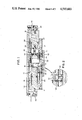
- FIG. 1 is a sectional elevational view of an asymmetrically accelerated vibrator for feeding materials.
- FIG. 2 is a sectional view of an example of a valve which can be employed instead of a multiple opening on the multiple air feed to modify the embodiment of the invention shown in FIG. 1,
- FIG. 3 is planar view of the embodiment of FIG. 1,
- FIG. 4 is a time location diagram of the motion of the asymmetric vibrator
- FIG. 5 is an elevational sectional view of a second embodiment
- FIG. 6 is a detail view of the air exhaust of the embodiment of FIG. 5.
- a case 10 to hold various recesses and lines for the flow of compressed air and for the motion of two pistons.
- the case is preferably made from a material which is stable and allows the motion of pistons. Materials which are suitable include such materials generally used for the construction of automobile engines. In particular cast iron is a preferred material. Materials which can also be suitable include aluminum and plastic.
- a connection 12 is provided to feed compressed air into the various compartments of this device.
- the block comprises two recesses adapted for two pistons, where the pistons run in a parallel direction.
- the first piston 14 runs in relatively smaller diameter bore of the bore 16 of the casing.
- the second piston 18 runs in a somewhat larger diameter bore of the bore 20 in the casing.
- the first piston comprises a groove for an o-ring surrounding the periphery of the piston in order to provide a seal against leakage of air.
- Several feeds for compressed air are connected from the air line to the first bore 16.
- FIG. 1. shows three such feeds 22, 24 and 26.
- the diameter of the feed 22 is smaller than that of feed 24 and that again is smaller than the diameter of feed 26.
- the feed 22 is disposed relatively close to the bottom of the bore 16.
- Preferably the feeds are spaced about equidistantly.
- the diameter of the first feed 22 can be about 0.5 to 2 millimeters and is preferably around 1 millimeter.
- the diameter of the second feed 24 can be from about 1 to 2 millimeters and is preferably around 1.6 millimeters and the diameter of the third feed 26 can be from about 2 to 4 millimeters and preferably is around 3.2 millimeters. This arrangement of the feeds ensures that the piston accelerates when it moves further out.
- a second piston 18 which has a larger diameter than the first piston 14 and this piston moves in a bore 20 of the case.
- An o-ring 28 is provided to seal the volume in the bore to press against the second piston.
- the second piston is provided with a bar 32 attached to its front base extending further into the bore. Due to the protruding bar 32 and the construction of the piston 18, the feed line 30 connecting the bore hole with the compressed air feed 12 remains always outside of the region which is covered by the motion of the second piston. This can be achieved for example by having the center part of the piston 18 protrude further into the bore hole as compared to the outer ring of the piston cylinder.
- the bar 32 is provided with a head 34 valve 36 which is disposed around the bar 32 and can slide along that bar.
- valve 36 The purpose of the valve 36 is to open the feed opening 30 and close the discharge opening 38 and vice versa. Feed throughs 40 are provided such that the volume in the bore 20 on the two sides of the valve 36 is communicating through the valve 36.
- the valve 36 is constructed such that one of the feed line 30 or the discharge 38 is closed or open and when one is open the other one is closed.
- the feed line 30 is of a relatively large diameter.
- the discharge line 38 is fed to an exhaust 42.
- the second piston 18 is attached to a holder 44 with a screw 46.
- the first piston 14 is attached to a holder 48 with a screw 50.
- the two holders in turn are connected by a plate 52 which is screwed to the first holder 44 and the second holder 48.
- FIG. 2 shows a small valve which provides different flow speed in different directions.
- the valve 60 is moved into the bore 62 and substantially closes the opening 66.
- the air flow in this situation is limited by the small diameter of the bore 68.
- the first piston is moved outward such that the air volume in the bore 16 increases.
- the air pressure in the volume 16 in the first bore is larger and this presses the valve 60 away from the opening 66 and allows a faster passage of air in this situation.
- the mode of operation of the asymmetric accelerated vibrator for material transport is as follows:
- the second piston is larger than the first piston.
- the inlet opening of the second piston is of such dimension as to move the second piston very rapidly upon opening of the passage 30.
- the opening 30 becomes shut, the air is cut off and the exhaust port 38 is opened. Since the second bore has a larger volume of air and a smaller size discharge port this induces the piston to come momentarily to a stop or to hesitate.
- the air pressure exerted on the first piston takes over and direction of motion reverses.
- the first piston starts to move slowly at first due to the construction of the air feed in and then picks up speed as the second and third feed lines are opened. This cycle continues until the second piston pushes against the valve 36 and moves the valve inwardly such that the port 30 opens and the discharge valve 38 closes.
- the larger pressure forming in the second bore causes the vibrator to stop and to reverse its motion, since the force exerted on the larger piston 18 is larger compared to the force exerted on the smaller diameter piston 14.
- the combination of the larger piston 18 with the valve 36 leads to reciprocal motion of the two pistons.
- the return of the reciprocal motion in the case where the large feed 30 opens is very fast due to the large bore diameter of the feed 30.
- the reversal of the motion in the case where the smaller volume is completely filled with air is much slower, since the discharge opening 38 is relatively small and the volume filled with compressed air relatively large such that the large volume of compressed air ahead of the second piston 18 opposes the backward motion of the second piston 18, which is fed with compressed air initially only by the small line 22.
- the combination of this asymmetrically accelerated vibrator with a transport chute or transport surface results in transport of materials in one direction.
- the fast motion accelerates the material to a relatively fast speed and the hesitation or stoppage of the piston results in a sliding continuation motion of the particles which results in a shift of the location of the material relative to the location of the support attached to the plate 52.
- This asymmetric accelerated vibrator can be used attached to transport sheets for transporting material such as screws.
- the fast motion of the second piston followed by the hesitation results in a continuation of the motion of the material on the sheet during the hesitation time. Then the sheet runs in the opposite direction taking the materials with it. None happens relative to the location of the material on the sheet during this cycle.
- another forward motion results associated with imparting a fast speed to the material followed by another time of hesitation during which the material moves another distance.
- This asymmetric accelerated vibrator allows removal of parts and material from areas which are inaccessible or inconvenient to reach by other means such as under a machine or a punch press.
- this asymmetric accelerated vibrator does not require any electrical connections since it is operated by compressed air. This allows application of this vibrator in areas where electrical currents and voltages are to be avoided. If such a tray is attached to one vibrator this can be followed by more trays and can result in an upward motion of the material placed on the trays. When enough air has discharged from the second bore the return side takes over since the small port at front of this first piston starts to move slowly at first and picks up speed as the second and third port are opened.
- a small valve as shown in FIG. 2 can be installed in the first port on the return side of the first bore. This valve allows the air to return faster during the time of a forward stroke. A small port in the valve controls the flows of the incoming air once the return stroke is under way.
- FIG. 4 shows a time-position diagram of the vibrator. The time is plotted on the abscissa and the location is plotted on the ordinate. It can be recognized that the speed is much larger in a first direction 91, where the large piston is directly driven by the compressed air, and smaller in the other direction 93. At 92 one can recognize that the velocity increases slowly like a parabola and this indicates that the acceleration is about constant and no initial jerk occurs, which would cause a sliding of material disposed on the vibrator. The large acceleration occuring at the other point of reversal is such that most materials start to slide as the acceleration is larger than the static friction.
- the average speed for the fast motion can be about 3 to 5 times the average speed of the slow motion cycle.
- FIG. 5 is a view of a preferred embodiment.
- the air intake of the large diameter recess chamber is controlled by a valve 102 connected to a line running to the air intake port 112.
- the valve 102 opens if the valve member 136 is pushed deeper into the recess chamber by the compressed air.
- the outer cylinder of the valve member has a bevel in the outer front in order to properly engage the valve 102, and the bevel is followed by a cylindrical section with a diameter smaller than the inner diameter of the recess chamber to allow the valve 102 to be kept in open position.
- the exhaust is provided via an opening 130 in the wall of the recess chamber, which is then led around downwardly into a slot 135 in the foot support of the vibrator.
- a slot elongated in the direction of vibration motion runs on the outside of a bore 123, wherein a piston 125 attached to the vibrating parts moves for control of the exhaust air flow.
- the further piston 125 is to a limit position of the direct motion of the first piston, the lower is the flow resistance encountered by the exhaust air coming from the larger diameter recess chamber.
- the more precise control of the flow pattern of the compressed air into and from the layer recess eliminates substantially the need to specifically control the flow pattern into the smaller recess.
- the bar 132 can also be provided at its end with elastic springing damping members corresponding to the elastic springing damping members 33 of the embodiment of FIG. 1 in order to cushion the impact. Items shown in FIG. 6 correspond in general to those of FIG. 1 and only some of the changes have been newly numbered.
- FIG. 6 illustrates the exhaust line from the larger diameter recess chamber.
- the opening 130 is connected via a line to a slot 135 in the foot 133 of the vibrator.
- This slot communicates with a longitudinal slot in the wall of a bore 123 and the flow path resistance for the exhaust air is controlled by the position of the small piston 125.
- the slot 137 can have a width of from about 0.2 to 0.5 millimeter and was milled to 0.015 inch in parallel with the exhaust tube with the small piston 125 controlling the flow.
- the position of the piston end is adjusted to allow initially only a very small amount of air to discharge. At this time the reversing acceleration of the vibrating parts is low, that is hesitation occurs.
- the small piston 125 moves back out of the bore it uncovers most of the slot opening and allows the air to exhaust faster and an increase in speed of the vibrating parts. The low acceleration and gradual increase in speed are needed to keep for example material moving together with a tray.
- the tool does not use any springs in the ports for holding or activating certain valves.
- the absence of springs increases the lifetime and reduces the service requirements of such a tool.
- Using the other side of valve to trap the air in the bottom of the bore acts to provide a cushion at the end of each stroke of the second piston.
- the asymmetrically accelerated vibrator runs at about 300 to 550 strokes per minute.
- the intake opening can be made larger if more speed is desired but this requires more air volume.
- a further advantage of this construction is that only one level of pressure or compressed air is required.
- the guidance of the piston must be fairly perfect and it should be with a tolerance of about 120 microns. Bearings are provided from teflon. In the case of larger units ball bearing can be used.
- the relative diameter of the smaller piston to the larger piston can be from about 1 to 1.25 to about 1 to 2.
- the intake port can be from about 2 to 5 millimeters and is preferably about 3.6 millimeters.
- the discharge opening can be from about 2 to 5 millimeters and is preferably about 3.2 millimeters. It is preferred to have the discharge opening of the second bore of slightly less diameter than the intake opening of the same bore.
Landscapes
- Engineering & Computer Science (AREA)
- Mechanical Engineering (AREA)
- Apparatuses For Generation Of Mechanical Vibrations (AREA)
Abstract
Description
Claims (18)
Priority Applications (1)
| Application Number | Priority Date | Filing Date | Title |
|---|---|---|---|
| US06/628,769 US4593603A (en) | 1984-07-09 | 1984-07-09 | Asymmetrically accelerated vibrator for feeding materials |
Applications Claiming Priority (2)
| Application Number | Priority Date | Filing Date | Title |
|---|---|---|---|
| US06/628,769 US4593603A (en) | 1984-07-09 | 1984-07-09 | Asymmetrically accelerated vibrator for feeding materials |
| EP19860100822 EP0231406B1 (en) | 1986-01-22 | 1986-01-22 | Asymmetrically accelerated vibrator for feeding materials |
Publications (1)
| Publication Number | Publication Date |
|---|---|
| US4593603A true US4593603A (en) | 1986-06-10 |
Family
ID=26101631
Family Applications (1)
| Application Number | Title | Priority Date | Filing Date |
|---|---|---|---|
| US06/628,769 Expired - Lifetime US4593603A (en) | 1984-07-09 | 1984-07-09 | Asymmetrically accelerated vibrator for feeding materials |
Country Status (1)
| Country | Link |
|---|---|
| US (1) | US4593603A (en) |
Cited By (10)
| Publication number | Priority date | Publication date | Assignee | Title |
|---|---|---|---|---|
| US4971159A (en) * | 1988-04-12 | 1990-11-20 | G. G. B. Industries, Inc. | Micropositioner |
| US5303826A (en) * | 1990-02-13 | 1994-04-19 | Refakt Anlagenbau Gmbh | Method and apparatus for separating different plastic products |
| US5467859A (en) * | 1994-01-19 | 1995-11-21 | Vibro Industries, Inc. | Vibrator for transporting articles |
| US5816386A (en) * | 1996-07-15 | 1998-10-06 | Allan M. Carlyle | Fluidizer conveyor |
| US6230875B1 (en) | 1999-05-14 | 2001-05-15 | Allan M. Carlyle | Synchronized vibrator conveyor |
| US20050098028A1 (en) * | 2003-11-10 | 2005-05-12 | Johnson Leroy A. | Asymmetrically accelerated vibrator for feeding materials |
| US20070095579A1 (en) * | 2004-03-26 | 2007-05-03 | Ishida Co., Ltd. | Transport apparatus and combination weighing apparatus provided therewith |
| US20090229890A1 (en) * | 2005-01-20 | 2009-09-17 | Ishida Co., Ltd. | Transportation device and combinational weighing apparatus including the same |
| CN105149238A (en) * | 2015-05-18 | 2015-12-16 | 刘影 | Strong vibration pipe of potato weight grader |
| IT202100030968A1 (en) * | 2021-12-09 | 2023-06-09 | Bordignon S R L | PNEUMATIC MOTOR AND OBJECT CONVEYOR, PARTICULARLY TO EVACUATE WASTE |
Citations (11)
| Publication number | Priority date | Publication date | Assignee | Title |
|---|---|---|---|---|
| SU264090A1 (en) * | ||||
| US638489A (en) * | 1899-06-15 | 1899-12-05 | Chester B Albree | Motor for tools. |
| US860660A (en) * | 1906-12-29 | 1907-07-23 | Ernst Heldmaier | Reciprocating hydraulic motor. |
| US2590155A (en) * | 1948-07-15 | 1952-03-25 | Edward S Cannon | Silent or seminoiseless vibrator |
| US2837896A (en) * | 1955-04-22 | 1958-06-10 | Northrop Aircraft Inc | Hydraulic or pneumatic bi-directional impulse motor |
| US2861548A (en) * | 1957-02-20 | 1958-11-25 | Burgess | Vibrator |
| US2969044A (en) * | 1957-11-05 | 1961-01-24 | Leduc Rene | Hydraulic valve and servo-systems |
| US3274899A (en) * | 1964-12-31 | 1966-09-27 | Howard W Stump | Reciprocating fluid motor |
| DE1239948B (en) * | 1959-06-30 | 1967-05-03 | Stothert & Pitt Ltd | Double-acting pressure cylinder activated by pressure medium |
| US3628419A (en) * | 1969-08-21 | 1971-12-21 | Doughton Mfg Co Inc | Fluid-operated motor |
| US4448262A (en) * | 1982-05-19 | 1984-05-15 | Cooper Industries, Inc. | Pneumatic hammer |
-
1984
- 1984-07-09 US US06/628,769 patent/US4593603A/en not_active Expired - Lifetime
Patent Citations (11)
| Publication number | Priority date | Publication date | Assignee | Title |
|---|---|---|---|---|
| SU264090A1 (en) * | ||||
| US638489A (en) * | 1899-06-15 | 1899-12-05 | Chester B Albree | Motor for tools. |
| US860660A (en) * | 1906-12-29 | 1907-07-23 | Ernst Heldmaier | Reciprocating hydraulic motor. |
| US2590155A (en) * | 1948-07-15 | 1952-03-25 | Edward S Cannon | Silent or seminoiseless vibrator |
| US2837896A (en) * | 1955-04-22 | 1958-06-10 | Northrop Aircraft Inc | Hydraulic or pneumatic bi-directional impulse motor |
| US2861548A (en) * | 1957-02-20 | 1958-11-25 | Burgess | Vibrator |
| US2969044A (en) * | 1957-11-05 | 1961-01-24 | Leduc Rene | Hydraulic valve and servo-systems |
| DE1239948B (en) * | 1959-06-30 | 1967-05-03 | Stothert & Pitt Ltd | Double-acting pressure cylinder activated by pressure medium |
| US3274899A (en) * | 1964-12-31 | 1966-09-27 | Howard W Stump | Reciprocating fluid motor |
| US3628419A (en) * | 1969-08-21 | 1971-12-21 | Doughton Mfg Co Inc | Fluid-operated motor |
| US4448262A (en) * | 1982-05-19 | 1984-05-15 | Cooper Industries, Inc. | Pneumatic hammer |
Cited By (14)
| Publication number | Priority date | Publication date | Assignee | Title |
|---|---|---|---|---|
| US4971159A (en) * | 1988-04-12 | 1990-11-20 | G. G. B. Industries, Inc. | Micropositioner |
| US5303826A (en) * | 1990-02-13 | 1994-04-19 | Refakt Anlagenbau Gmbh | Method and apparatus for separating different plastic products |
| US5467859A (en) * | 1994-01-19 | 1995-11-21 | Vibro Industries, Inc. | Vibrator for transporting articles |
| US5816386A (en) * | 1996-07-15 | 1998-10-06 | Allan M. Carlyle | Fluidizer conveyor |
| US6230875B1 (en) | 1999-05-14 | 2001-05-15 | Allan M. Carlyle | Synchronized vibrator conveyor |
| US20050098028A1 (en) * | 2003-11-10 | 2005-05-12 | Johnson Leroy A. | Asymmetrically accelerated vibrator for feeding materials |
| US6971301B2 (en) | 2003-11-10 | 2005-12-06 | Vibro Industries, Inc. | Asymmetrically accelerated vibrator for feeding materials |
| US20070095579A1 (en) * | 2004-03-26 | 2007-05-03 | Ishida Co., Ltd. | Transport apparatus and combination weighing apparatus provided therewith |
| US7439454B2 (en) * | 2004-03-26 | 2008-10-21 | Ishida Co., Ltd. | Article transport apparatus having trough and reciprocating movement mechanism, and combination weighing apparatus provided therewith |
| US20090229890A1 (en) * | 2005-01-20 | 2009-09-17 | Ishida Co., Ltd. | Transportation device and combinational weighing apparatus including the same |
| US7754984B2 (en) * | 2005-01-20 | 2010-07-13 | Ishida Co., Ltd. | Transportation device and combinational weighing apparatus including the same |
| CN105149238A (en) * | 2015-05-18 | 2015-12-16 | 刘影 | Strong vibration pipe of potato weight grader |
| IT202100030968A1 (en) * | 2021-12-09 | 2023-06-09 | Bordignon S R L | PNEUMATIC MOTOR AND OBJECT CONVEYOR, PARTICULARLY TO EVACUATE WASTE |
| EP4194706A1 (en) * | 2021-12-09 | 2023-06-14 | Bordignon S.r.l. | Pneumatic motor and object conveyor, in particular for removing scraps |
Similar Documents
| Publication | Publication Date | Title |
|---|---|---|
| US4593603A (en) | Asymmetrically accelerated vibrator for feeding materials | |
| CN108348979B (en) | Stamping device | |
| KR19990063127A (en) | Combustion powered tools with improved combustion chamber fan motor suspension | |
| US10821590B2 (en) | Striking hand-held machine tool | |
| JP2005103728A (en) | Compressed air screwing machine | |
| US4088062A (en) | Fluid pressure operated impact mechanism | |
| US3892280A (en) | Portable pneumatic impact tool | |
| JPH07101699A (en) | Balancer | |
| US2408338A (en) | Hydraulic device | |
| US4483402A (en) | Paving breaker | |
| KR101191341B1 (en) | Air vibration device | |
| EP0231406B1 (en) | Asymmetrically accelerated vibrator for feeding materials | |
| US5161623A (en) | Percussion device | |
| US4192419A (en) | Conveyor | |
| MX2022007899A (en) | Material application device and pressing member. | |
| US10675742B2 (en) | Striking hand-held machine tool | |
| US3323602A (en) | Pneumatically operated stapler, nailing apparatus or the like | |
| US20180361552A1 (en) | Striking hand-held tool | |
| US5816341A (en) | Hammer mechanism | |
| CN1462226A (en) | Hammer drill and/or chisel hammer | |
| KR200363316Y1 (en) | Air vibrator | |
| US7810618B2 (en) | Vibration generator | |
| US6971301B2 (en) | Asymmetrically accelerated vibrator for feeding materials | |
| RU2799163C1 (en) | Pneumatic vibrator | |
| EP1661629B1 (en) | Vibratory apparatus for ejecting items |
Legal Events
| Date | Code | Title | Description |
|---|---|---|---|
| STCF | Information on status: patent grant |
Free format text: PATENTED CASE |
|
| AS | Assignment |
Owner name: VIBRO INDUSTRIES, INC., P.O. BOX 565, FOGELSVILLE, Free format text: ASSIGNMENT OF ASSIGNORS INTEREST.;ASSIGNOR:ELIZABETH M. JOHNSON (EXECUTRIX) TO LEROY A. JOHNSON DEC'D;REEL/FRAME:004941/0589 Effective date: 19880825 Owner name: VIBRO INDUSTRIES, INC.,PENNSYLVANIA Free format text: ASSIGNMENT OF ASSIGNORS INTEREST;ASSIGNOR:ELIZABETH M. JOHNSON (EXECUTRIX) TO LEROY A. JOHNSON DEC'D;REEL/FRAME:004941/0589 Effective date: 19880825 |
|
| FEPP | Fee payment procedure |
Free format text: PAYOR NUMBER ASSIGNED (ORIGINAL EVENT CODE: ASPN); ENTITY STATUS OF PATENT OWNER: SMALL ENTITY |
|
| FPAY | Fee payment |
Year of fee payment: 4 |
|
| REFU | Refund |
Free format text: REFUND OF EXCESS PAYMENTS PROCESSED (ORIGINAL EVENT CODE: R169); ENTITY STATUS OF PATENT OWNER: SMALL ENTITY |
|
| FPAY | Fee payment |
Year of fee payment: 8 |
|
| SULP | Surcharge for late payment | ||
| FPAY | Fee payment |
Year of fee payment: 12 |