US4593601A - Recoil spring system for self loading fire arms - Google Patents
Recoil spring system for self loading fire arms Download PDFInfo
- Publication number
- US4593601A US4593601A US06/593,391 US59339184A US4593601A US 4593601 A US4593601 A US 4593601A US 59339184 A US59339184 A US 59339184A US 4593601 A US4593601 A US 4593601A
- Authority
- US
- United States
- Prior art keywords
- slide
- spring
- frame
- receiving means
- tunnel
- Prior art date
- Legal status (The legal status is an assumption and is not a legal conclusion. Google has not performed a legal analysis and makes no representation as to the accuracy of the status listed.)
- Expired - Fee Related
Links
Images

Classifications
-
- F—MECHANICAL ENGINEERING; LIGHTING; HEATING; WEAPONS; BLASTING
- F41—WEAPONS
- F41A—FUNCTIONAL FEATURES OR DETAILS COMMON TO BOTH SMALLARMS AND ORDNANCE, e.g. CANNONS; MOUNTINGS FOR SMALLARMS OR ORDNANCE
- F41A3/00—Breech mechanisms, e.g. locks
- F41A3/64—Mounting of breech-blocks; Accessories for breech-blocks or breech-block mountings
- F41A3/78—Bolt buffer or recuperator means
- F41A3/82—Coil spring buffers
Definitions
- This invention relates to self loading fire arms of the pistol type in which a reciprocating breech block slide is employed, and which is provided with spring means for imparting a constant regular spring pressure in a forward direction upon the slide, this pressure serving to regulate the recoil of the slide on discharge of a cartridge in the barrel of the fire arm, and returning the slide to the forward battery position, the slide performing all the usual functions related to a self loading fire arm on its forward motion.
- a self loading fire arm of the pistol type having a reciprocating breech block slide and spring means for exerting pressure in a forward direction on said slide to regulate the recoil of said slide on discharge of a cartridge in the barrel of said fire arm
- said spring means comprising a pair of compression springs held in respective tunnels formed in the side walls of said slide and extending substantially the full length thereof, each said spring abutting at its forward end against the front wall of said slide and at its rear end against a respective stop on the frame of the fire arm, which on recoil of the slide passes through a slot at the rear of the slide connecting the tunnel to an exterior surface of the slide.
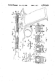
- FIG. 1 of the accompanying drawings represents, partly in elevation and partly in longitudinal vertical section, a self loading semi automatic pistol provided with means constructed and arranged in accordance with this invention for a spring system to furnish a reactive force to enable the slide and related parts to perform a correct firing, extraction, ejection, and cartridge feeding cycle, showing the pistol with the slide in the forward battery position, recoil spring system fitted;
- FIG. 2 is a perspective view of the front recoil spring guide and retainer, viewed from the left front;
- FIG. 3 is a perspective view of the front recoil spring guide and retainer, viewed from the left rear;
- FIG. 4 is an elevation view of the rear recoil spring guide
- FIG. 5 is a transverse vertical section of FIG. 1 upon line 1;
- FIG. 6 is a transverse vertical section of FIG. 1 upon line 2;
- FIG. 7 is a transverse vertical section of FIG. 1 upon line 3;
- FIG. 8 is a transverse vertical section of FIG. 1 upon line 4;
- FIG. 9 is a perspective view of the slide, viewed from front lower left;
- FIG. 10 is a perspective view of the frame, viewed from above and from the left.
- FIG. 11 is a longitudinal transverse section of the front slide along the axes of the recoil spring tunnels, showing removal or insertion of front and rear recoil spring guides with attached recoil springs.
- the slide B has two longitudinal parallel circular tunnels B1 and B2 which pass clear from the front of the slide to the position B3.
- Flat longitudinally extending horizontal planes B4 and B5 run parallel beneath each tunnel and two longitudinally extending vertical slots B7 and B8 pass from the rear of the slide, each slot passing along the axis of a tunnel and opening at a respective one of the planes B4 and B5, the slots extending lengthwise of the rear portion of each tunnel and terminating at the position B6 as shown in FIG. 1 and FIG. 9.
- the recoil spring P has at each end a coil of reduced diameter. Each spring holds at one end a recoil spring front guide Q and at the opposite end a recoil spring rear guide R.
- Each guide has an annular groove, R1 and Q1, into which the reduced end coils of the recoil spring securely fit.
- the complete spring unit of spring, front guide and rear guide is inserted into its respective tunnel, feeding the end R2 of the rear guide into cavity B15 inside each slide front wing and thus into the continuation of holes B1 and B2 at the rear of each cavity.
- the rear spring guides are pushed rearwards in each spring tunnel B1 and B2 until each front spring guide enters the respective cavity, when the front Q2 of each front spring guide can be pushed into the cavity.
- spring pressure When pushed into the cavity spring pressure will force each front spring guide forwards against the rear of wall B9 and the forward section Q3 of each spring guide can enter the rear of hole B1 and B2 in each wall B9.
- each front spring guide will prevent the spring guides from passing through the hole B1 or hole B2 in each wall B9. With the rear guides forced rearwards by recoil spring pressure against the termination of each spring tunnel at point B3 in the slide the recoil spring units will be securely retained in their respective tunnels and thus in the slide.
- the slide is mounted onto the frame A from the front, the frame guide ribs A9 engaging in the slide grooves B11.
- the slide is retracted to the rear, and the rear recoil spring guides will impinge upon the frame wings A2, thereby starting to compress the recoil springs before the slide is in the front battery position as shown in FIG. 1 as shown in FIG. 1 the frame wings A2 comprise stops which, when the slide is in its forward battery position illustrated, are received in the slot portions which extend through the rear wall of the slide.
- the space B12 shown in FIG. 1 represents the amount of compression the recoil springs are subjected to when the slide is in the battery position.
- the slide is prevented from moving forward off the frame by the barrel C being held by a locking block seating against frame pin A1.
- the locking block having a wing passing transversely through a recess under the barrel and engaging in recesses B13 of the slide.
- the concave circular cavity Q5 in the front of the front spring guide is intended to help disassembly of the recoil spring units from the slide.
- An object such as the point of a ball point pen, the pointed end of a nail, the pointed bullet end of a rifle cartridge, or any other suitable shaped object, can be placed in the cavity Q5 and pressure exerted against the tension of the respective spring.
- the forward section Q3 of the respective spring guide is clear of hole B1 or B2 in walls B9 the front of Q2 of the spring guide can be pivoted inwards to clear the inward edge of the wall B9.
- the recoil spring will allow the pivoting of the front recoil spring guide and the removal of the whole recoil spring unit from the tunnel B1 or B2, whichever, the recoil spring flexing inwards in cavity B15 and passing through an inwardly directed longitudinally extending aperature communicating with the cavity B15 at the forward end of the tunnel B1 or B2 as it is withdrawn, as it would when being inserted, and there would be ample clearance to allow the rear recoil spring guide to clear the tunnel, and with the recoil spring attached, also with the spring flexed at the front R3 of the rear guide, the rear guide can be removed inwards from cavity B15, as in FIG. 11.
Abstract
Description
Claims (5)
Applications Claiming Priority (2)
| Application Number | Priority Date | Filing Date | Title |
|---|---|---|---|
| GB8308439 | 1983-03-28 | ||
| GB8308439 | 1983-03-28 |
Publications (1)
| Publication Number | Publication Date |
|---|---|
| US4593601A true US4593601A (en) | 1986-06-10 |
Family
ID=10540328
Family Applications (1)
| Application Number | Title | Priority Date | Filing Date |
|---|---|---|---|
| US06/593,391 Expired - Fee Related US4593601A (en) | 1983-03-28 | 1984-03-26 | Recoil spring system for self loading fire arms |
Country Status (1)
| Country | Link |
|---|---|
| US (1) | US4593601A (en) |
Cited By (10)
| Publication number | Priority date | Publication date | Assignee | Title |
|---|---|---|---|---|
| WO1997029337A1 (en) * | 1996-02-12 | 1997-08-14 | Sturm, Ruger & Company, Inc. | Firearm frame including a firearm barrel and trigger mount control mechanism |
| US5717156A (en) * | 1996-02-12 | 1998-02-10 | Smith & Wesson Corp. | Semi-automatic pistol |
| WO2011113983A1 (en) * | 2010-03-16 | 2011-09-22 | Extreme Polymer Research S.L. | Semi-automatic pistol |
| US10184736B2 (en) * | 2016-01-19 | 2019-01-22 | American Classic Arms, LLC | Frame slide guide system |
| US20190195582A1 (en) * | 2017-12-22 | 2019-06-27 | Sig Sauer, Inc. | Handgun with forward assist |
| USD854642S1 (en) | 2018-01-05 | 2019-07-23 | Sig Sauer, Inc. | Semiautomatic handgun |
| US10641562B2 (en) * | 2018-06-22 | 2020-05-05 | James Robert Patrick, IV | Firearm with recoil mitigation |
| US10648769B2 (en) | 2017-12-22 | 2020-05-12 | Sig Sauer, Inc. | Handgun grip module with a reinforcing bracket |
| US10724814B2 (en) | 2017-12-22 | 2020-07-28 | Sig Sauer, Inc. | Handgun safety mechanism |
| US11808540B2 (en) | 2022-03-16 | 2023-11-07 | Sig Sauer, Inc. | Safety mechanism for blowback firearm |
Citations (8)
| Publication number | Priority date | Publication date | Assignee | Title |
|---|---|---|---|---|
| GB191120367A (en) * | 1912-04-06 | 1912-11-14 | Catherine Chapman | Improvements relating to Gowns, Coats, Cloaks and like Articles of Wearing Apparel. |
| US1105416A (en) * | 1914-03-13 | 1914-07-28 | Warner Arms Corp | Automatic hand-firearm. |
| US1143472A (en) * | 1914-07-20 | 1915-06-15 | William John Whiting | Hammerless automatic small-arm. |
| US1276716A (en) * | 1917-03-30 | 1918-08-27 | John M Browning | Firearm. |
| US1277379A (en) * | 1917-03-30 | 1918-09-03 | Colt S Mfg Co | Firearm. |
| US1557435A (en) * | 1925-02-24 | 1925-10-13 | Lucius N Diehm | Firearm |
| US2135992A (en) * | 1936-02-13 | 1938-11-08 | Walther Carl | Automatic pistol |
| US2248445A (en) * | 1938-12-16 | 1941-07-08 | High Standard Mfg Company | Automatic pistol |
-
1984
- 1984-03-26 US US06/593,391 patent/US4593601A/en not_active Expired - Fee Related
Patent Citations (8)
| Publication number | Priority date | Publication date | Assignee | Title |
|---|---|---|---|---|
| GB191120367A (en) * | 1912-04-06 | 1912-11-14 | Catherine Chapman | Improvements relating to Gowns, Coats, Cloaks and like Articles of Wearing Apparel. |
| US1105416A (en) * | 1914-03-13 | 1914-07-28 | Warner Arms Corp | Automatic hand-firearm. |
| US1143472A (en) * | 1914-07-20 | 1915-06-15 | William John Whiting | Hammerless automatic small-arm. |
| US1276716A (en) * | 1917-03-30 | 1918-08-27 | John M Browning | Firearm. |
| US1277379A (en) * | 1917-03-30 | 1918-09-03 | Colt S Mfg Co | Firearm. |
| US1557435A (en) * | 1925-02-24 | 1925-10-13 | Lucius N Diehm | Firearm |
| US2135992A (en) * | 1936-02-13 | 1938-11-08 | Walther Carl | Automatic pistol |
| US2248445A (en) * | 1938-12-16 | 1941-07-08 | High Standard Mfg Company | Automatic pistol |
Cited By (14)
| Publication number | Priority date | Publication date | Assignee | Title |
|---|---|---|---|---|
| WO1997029337A1 (en) * | 1996-02-12 | 1997-08-14 | Sturm, Ruger & Company, Inc. | Firearm frame including a firearm barrel and trigger mount control mechanism |
| US5717156A (en) * | 1996-02-12 | 1998-02-10 | Smith & Wesson Corp. | Semi-automatic pistol |
| US5741996A (en) * | 1996-02-12 | 1998-04-21 | Sturm, Ruger & Company, Inc. | Firearm frame including a firearm barrel and trigger mount control mechanism |
| CN1071447C (en) * | 1996-02-12 | 2001-09-19 | 施图尔姆鲁格有限公司 | Firearm frame including firearm barrel and trigger mount control mechanism |
| WO2011113983A1 (en) * | 2010-03-16 | 2011-09-22 | Extreme Polymer Research S.L. | Semi-automatic pistol |
| ES2372204A1 (en) * | 2010-03-16 | 2012-01-17 | Extreme Polymer Research, S.L. | Semi-automatic pistol |
| US10184736B2 (en) * | 2016-01-19 | 2019-01-22 | American Classic Arms, LLC | Frame slide guide system |
| US20190195582A1 (en) * | 2017-12-22 | 2019-06-27 | Sig Sauer, Inc. | Handgun with forward assist |
| US10465999B2 (en) * | 2017-12-22 | 2019-11-05 | Sig Sauer, Inc. | Handgun with forward assist |
| US10648769B2 (en) | 2017-12-22 | 2020-05-12 | Sig Sauer, Inc. | Handgun grip module with a reinforcing bracket |
| US10724814B2 (en) | 2017-12-22 | 2020-07-28 | Sig Sauer, Inc. | Handgun safety mechanism |
| USD854642S1 (en) | 2018-01-05 | 2019-07-23 | Sig Sauer, Inc. | Semiautomatic handgun |
| US10641562B2 (en) * | 2018-06-22 | 2020-05-05 | James Robert Patrick, IV | Firearm with recoil mitigation |
| US11808540B2 (en) | 2022-03-16 | 2023-11-07 | Sig Sauer, Inc. | Safety mechanism for blowback firearm |
Similar Documents
| Publication | Publication Date | Title |
|---|---|---|
| US7810271B2 (en) | Modular rifle systems and methods | |
| US2834137A (en) | Magazing charger | |
| US4502237A (en) | Magazine follower for automatic pistols | |
| US10852086B1 (en) | Magazine extension for a firearm | |
| US3776095A (en) | Weapon conversion bolt assembly device | |
| EP2943733B1 (en) | Interchangeable buttstock system for firearms | |
| US9797666B2 (en) | Convertible lower receiver | |
| US4593601A (en) | Recoil spring system for self loading fire arms | |
| US4485723A (en) | Fire arm accessory with recoil absorbing secondary buffer arrangement | |
| US4299046A (en) | Single-shot survival rifle | |
| US20160209140A1 (en) | Rifle Magazine | |
| US4541192A (en) | Hinge device for firearms | |
| US7377066B2 (en) | Firearm with a readily interchangeable bolt face | |
| US4970818A (en) | Magazine for fire-arms | |
| US20160040956A1 (en) | Lever-action modular tactical rifle | |
| US2856716A (en) | Automatic rifle with a combined movable chamber and magazine | |
| US4440062A (en) | Reversible bolt for firearms | |
| US5341587A (en) | Ejector and cartridge positioner | |
| US10386141B2 (en) | Automatic magazine ejection follower insert system | |
| US9857147B2 (en) | Rail system for a rifle | |
| US4574509A (en) | Ambidextrous cartridge magazine retaining catch for self loading fire arms | |
| US5416998A (en) | Adapter for rifle magazine | |
| US11624569B2 (en) | Striker fired pistol | |
| GB2137325A (en) | Recoil spring system for self-loading firearms | |
| US20160109207A1 (en) | Hybrid left handed 1911 pistol |
Legal Events
| Date | Code | Title | Description |
|---|---|---|---|
| FPAY | Fee payment |
Year of fee payment: 4 |
|
| AS | Assignment |
Owner name: VICTORY ARMS COMPANY LIMITED, ENGLAND Free format text: ASSIGNMENT OF ASSIGNORS INTEREST.;ASSIGNOR:SMITH, DAVID E.;REEL/FRAME:006179/0058 Effective date: 19920505 Owner name: VICTORY ARMS (ISLE OF MAN) LIMITED, ISLE OF MAN Free format text: ASSIGNMENT OF ASSIGNORS INTEREST.;ASSIGNOR:VICTORY ARMS COMPANY LIMITED;REEL/FRAME:006179/0053 Effective date: 19920505 |
|
| AS | Assignment |
Owner name: SWISS BANK CORPORATION, ENGLAND Free format text: ASSIGNMENT OF ASSIGNORS INTEREST.;ASSIGNOR:VICTORY ARMS (I.O.M.) LIMITED;REEL/FRAME:006253/0711 Effective date: 19891122 |
|
| REMI | Maintenance fee reminder mailed | ||
| LAPS | Lapse for failure to pay maintenance fees | ||
| FP | Lapsed due to failure to pay maintenance fee |
Effective date: 19940615 |
|
| STCH | Information on status: patent discontinuation |
Free format text: PATENT EXPIRED DUE TO NONPAYMENT OF MAINTENANCE FEES UNDER 37 CFR 1.362 |