US458434A - Machine - Google Patents
Machine Download PDFInfo
- Publication number
- US458434A US458434A US458434DA US458434A US 458434 A US458434 A US 458434A US 458434D A US458434D A US 458434DA US 458434 A US458434 A US 458434A
- Authority
- US
- United States
- Prior art keywords
- plate
- arm
- needles
- thread
- cam
- Prior art date
- Legal status (The legal status is an assumption and is not a legal conclusion. Google has not performed a legal analysis and makes no representation as to the accuracy of the status listed.)
- Expired - Lifetime
Links
- 210000002683 Foot Anatomy 0.000 description 12
- 239000004744 fabric Substances 0.000 description 12
- 239000000463 material Substances 0.000 description 12
- 238000009958 sewing Methods 0.000 description 10
- 238000009954 braiding Methods 0.000 description 8
- 238000007688 edging Methods 0.000 description 6
- 230000004048 modification Effects 0.000 description 6
- 238000006011 modification reaction Methods 0.000 description 6
- 210000003414 Extremities Anatomy 0.000 description 4
- 230000015572 biosynthetic process Effects 0.000 description 4
- 230000000694 effects Effects 0.000 description 4
- 238000005755 formation reaction Methods 0.000 description 4
- 210000001331 Nose Anatomy 0.000 description 2
- 240000001439 Opuntia Species 0.000 description 2
- 235000005308 Pandanus Nutrition 0.000 description 2
- 241000233930 Pandanus Species 0.000 description 2
- 210000003371 Toes Anatomy 0.000 description 2
- 239000003086 colorant Substances 0.000 description 2
- 150000001875 compounds Chemical class 0.000 description 2
- 230000000875 corresponding Effects 0.000 description 2
- 238000009957 hemming Methods 0.000 description 2
- 239000011435 rock Substances 0.000 description 2
Images


Classifications
-
- D—TEXTILES; PAPER
- D05—SEWING; EMBROIDERING; TUFTING
- D05B—SEWING
- D05B73/00—Casings
- D05B73/04—Lower casings
- D05B73/12—Slides; Needle plates
Definitions
- My said invention relates to attachments for application to ordinary lock-stitch sewingmachines, the said attachments enabling such ordinary machines to be used temporarily for stitching button-holes or for edging or linestitching cloth and other materials, or for overcasting seams or the like.
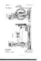
- FIG. 1 is a side View of an ordinary lock-stitch Singer sewing-machine with my invention attached thereto.
- Fig. 2 is a front view of the same.
- Fig. 3 is an enlarged side View of the aforesaid improved attachment.
- Fig. 4 is a front view.
- Fig. 5 is a plan.
- Fig. G is a separate view ⁇ of the shifting or shunting plate.
- Fig. 7 is a side view of a sewing-machine, similar to Fig. l' and showing a modification of my improved attachment.
- Fig. S is a front view of Fig. 7.
- Fig. 9 is an enlarged detail front view of the aforesaid modifed improved attachment.
- Fig. 10 is a side view.
- Fig. 11 is a detail view of the shunting-plate.
- Fig. 12 is a horizontal section of Fig. 9, Sheet 4, at the line A B.
- Fig. 13 is a separate view of the presser-foot and button-hole guide.
- Fig. 13n is a crossmode of imparting motion to the arm for carrying the binding or plaiting thread backward and forward across the path of the needles.
- Figs. 1S and 19 illustrate a button-hole stitch on an enlarged scale during dierent periods of formation.
- Fig. 2O also illustrates inplan the formation of the stitch, a portion of the stitching being shown complete.
- Fig. 2l is an edge View of the stitch in Fig. 20.
- Fig. 22 illustrates in plan one of the several. varieties of stitching which can be obtained by modifying the tension of the threads.
- the ordinary frame or arm of the machine is marked a, and the needle-bar is marked h.
- the needle-bar I affix two needles c d.
- the material is held down in the usual manner bythe presserfoot e, whichy is shown separately at Fig. 13, and a toe or shield e, projecting downward from the lower side of the presser-foot, enters the button-hole or comes against the edge of the material, so as to act as a guide while the material is being fed.
- the shield or projection e is shown in horizontal section at Fig. 13. It partly incloses and protects the needle cl.
- the presser-foot is slit opposite the needle-gate, as clearly seen in Fig. 13, so as-to allow of easy threading and adjustment.
- the distance between the letters Qc represents lthe length of each feed of the sewing-machine.
- the needles operate in the usual way and form the parallel rows of stitches c CZ.
- the so-called bindingor plaiting7 thread g' which appears in Fig. 22 as a continuous zigzag, is thrown across and in front of the needles c CZ during each downstroke and is pulled behind the'needles at the end of the upstroke, so that on the next downstroke the needles strike in front of the binding-thread g and of course throw the stitches c Cl over the binding-thread g at each stroke.
- the shuttle-thread f binds the stitches c d on the under side of the fabric.
- the upper edge of the Vbutton-hole is about in the position of the approximately straight line sought to be occupied by the bindingthread g', and looking at Fig. 2O it will be seen that under the conditions of tension which have produced this stitch the bindingthread g is thrown as a waving line along the upper edge of the button-hole, (this waving line being the nearest approximation to a straight line which it has been permitted to assume,) while the stitches c are drawn over toward the upper edge of the buttonhole and the stitches d (which in the case of a button-hole, it will be remembered, do not penetrate the cloth) are pulled up from the bottom edge of the button-hole, where they have been bound by the shuttle-thread to the top edge, so that the loops of the two stitches c d and the waving binding-thread g present the usual or necessary plaited or woven ridge which should appear all round the upper edge of aproperly-stitched button-hole.
- Fig. 18 the thread d', proceeding from the needle d to the button-hole, is shown broken short oit, ⁇ so as to prevent it from coming in front of and thereby obscuring the last-formed stitch or loop d', clearly appearing in the figure.
- the first or preferred form of the attachable and detachable mechanism which I have devised for producing the hereinbefore-described vibration of the arm g across the path of the needles, is illustrated in Sheets 1 and 2 of the drawings.
- the bracket fz' which carries the whole of the moving parts of the attachment, is secured to the side of the needle-bar box d. by means of a screw h or other suitable means.
- bracket e' which carries the attachment
- needles c clsay for example, the needle c.
- a second sliding shunting-plate o In the face of the iiat plate n I form a Y- shaped slot n3, and behind the plate n there is a second sliding shunting-plate o, having a slot o in its face, of the form shown in Fig. 6, Sheet 2.
- the shunting-plate o is held to the back of the plate nby the screws p, which occupy horizontal slots in the plate 0.
- Coiled springs p hold the plate 0 with an elastic pressure against the back of the plate/n., the horizontal slots limiting the sliding traverse of the plate o behind the plate frz..
- a finger q projecting from the top of the needle-bar b, passes through the slots of both the camplate n and the shunting-plate o, and by act- -ing on the slots the said finger slides the camplate fn to'and fro as the needle-bar, and consequently the finger, rises and falls. It will be evident tLatunless means were providedV to shunt the bar q from one arm of the Y- shaped slot in the cam-plate n opposite to the other arm at each downstroke the finger q would simply play up and down in one side or limb of the Y-shaped slot.
- the inner shunting-plate o provides the required shunting means-that is to say, at each downstroke of the bar q the inner shunting-plate o has been so previously moved as to present a continuation of the incline constituted by the Y-slot in the cam-plate n to the iingerqsuficient to carry the cam-plate n past the center or dead-point, and thus bring the Vfinger q opposite to the farther arm of the Y-shaped slot in the cam-plate, so that on the upstroke of the finger q it enters this farther arm and completes the movement of the plate nY to one side or the other.
- the linger q shifts the inner shunting-plate o relatively to the outer plate n in such a manner that on its return downstroke a similar continuation of the inclined slot on that side is presented to the finger q, and a corresponding continuation of the movement of the cam-plate past the center or dead-point is effected, so that on its upstroke the finger q enters the inclined slot on the Vits original starting-point.
- Fig. 4f is a front view of the cam-plate n and attached parts, the Y- shaped slot n3 clearly appears.
- the inner shunting-plate o is also indicated partly in v dotted lines behind the plate n, the part-s of the plate 0, which appear through and behind the slot n3 being cross-hatched to distinguish them from the plate n.
- Fig. 6 a separate front view is given of this inner shunting-plate 0.
- the plan view, Fig. 5, also shows the relative position of the inner shuntingplate o to the outer cam-plate at. Now when the finger q,which is indicated in dotted lines at Fig.
- FIG. 7 to 12, Sheets 3,4, and 5 A modification of the means for imparting the requisite motion to the arm g is shown in Figs. 7 to 12, Sheets 3,4, and 5.
- the slotted cam-plate n10 is made curved instead of being at like the plate n, before referred to, and instead of sliding to and fro on a rod or on trunnions between supports, as in the case of the said plate n, the said plate 'n.10 is pivoted by its radial arms n@ m12 upon stud jm, so as to be capable of rocking freely upon this stud.
- a second concentric shunting-plate 010 In the face of the cam-plate n10 I form a Y-shaped slot w13, as already described, and behind the cam-platen10 and centered upon the same stud 310 there is a second concentric shunting-plate 010, separately shown at Fig. 11, having also a Y-shaped slot o, but inverted with relation to the slot in the cam-plate n10.
- the relative positions of the cam-plate n10-and shuntingplate 010 are clearly shown at Fig. l2, which is a sectional view of Fig. 9 at theline A B.
- the said second inner slotted shunting-plate o10 has a flat sprin g p10, secured toit by a screwpin 1911.
- the tail of the spring p10 passes through a slit in the bottom arm of the inner shunting-plate 010 and presses on the lower arm n12 of the outer cam-plate n10.
- the object of the flat spring is the same as that of the coiled springs p in Figs. 1 to -viz., to
- a bar Q10 fastened to the top of the needle-bar, projects through the Y-slots of both cam and shunting plate n10 and 0, as in the former case, and by acting in the slots vibrates the cam-plate 'n10 to and fro as the needle-bar rises and falls.
- the arm g is attached at m10 to the extension n from the plate n10, and a loosely-pivoted link Z connects the arm g to the foot of the bracket t and thus circumscribes and guides the movements of the arm gin the manner already described with reference to the linkZ in the foregoing figures.
- Fig. 14 is a side View, and Fig. 15 a plan, of a sewing-machine with another modified form of my improved attachment.
- the cam 1' is shown separately in Figs. 16 and 17.
- the slide-supports might be parts ofv a single bracket secured to the arm a by a single screw, as in the case of the bracket t, described with reference to the foregoing iigures.
- a finger Q1 extending from the bar u, enters the groove in the cam 0' with the result that when the cam revolves the bar a is reciprocated to and fro.
- the bent double lever fw at 0c pivots the bent double lever fw at 0c, and to the lever w I secure the arm g.
- the said arm g is thus reciprocated to and fro in front of the needles, and by connecting the inner arm tu of the lever w by a link z to a fixed pivot z', projecting from an extension of the slide-support t, a sidelong rocking motion is also imparted to the lever w and arm g.
- the attachment shown in Figs. 14 and 15 is capable of being expeditiously and easily attached and removed by an unskilled person by means of the screws t?, or instead of the screws t2 clamps or other ordinary and easily manipulated means of attachment might be used.
- the complete attachment for manipulating the binding or plaiting thread g' is exceedingly simple, and can be attached and removed in a moment and by an unskilled person.
- the parts do not require any nice adjustment, and are not liable to get out of order while the whole attachment can be produced at a low cost.
- Vhat I claim is- 1.
- said arnl for reciprocating the lower end of said arm back and forth in front of the ncedles, and a horizontally-swinging link connecting said auxiliary arm with a stationary part of the sewing-machine, so as to cause the auxiliary arm to move back and forth in front of the needles in the path of a circle, substantially as set forth.
- An attachment for sewing-machines consisting of an auxiliary arm g, carrying a thread g', in combination with a reciprocating plate provided with a Y-shaped slot therein, into which a stud or extension on the needle -arnn b engages, said reciprocating plate being connected :to and operating said auxiliary arm, so as to reciprocate the said auxiliary arm back and forth in front of the needles, a shunt-plate behind said reciproeating plate and provided with a -shaped slot therein, into which the said stud or 'extension on the needle-arm h also engages, frictional connections between said reciprocating plate and said shunt-plate, and a horizontally swinging link Z, connecting said auxiliary arm g with a stationary part of the sewing-machine, so as to cause the said auxiliary arm to move back and forth in front of the needles in the path of a circle, substantially as set forth.
Description
. (No Modell.) 6 sheets-sheet 1.
R. TODD. SEWING MACHINE.
Patented 4 l- W/ misses. fb
/fwf/vra (No Model.) s sheets-sheet 2.
' R. TODD.
SEWING MACHINE.
tented Aug. 25, 1891.
u zit.
(Lm. 06ML.
Maremma, wsmncrou. uA c.
I/I//T/vfssfs.
mewleg.
.au t e e h.. S V fu e e h S 6 ...m N m D C DA OM TG Rm W E S d d o M 0 rN\ No. 458,434. Patented Aug. 25, 1891.
/NVE/v Tof? 04m M @ZM/e.
zdf/Ng,
(No Model.) 6 Sheetls-Sheet 5 R. TODD.
SEWING MACHINE.
No. 458,434. Patented Aug. 25.1891.
Imm ..414 mln' 1 s!!! "lllllh'n umillll MTA/5555s QM. 66M@ 6 Sheets-Sheet 6.
(No-Model.)
R. TODD'.
. SEWING MAGHINE. No. 458,434. Patented Aug. 25, 1891.
fla/.9
.1: lli."
MTNEssEs. /N vE/vToR.
Q @L/ A CMM @ag/2L. y gg@ f 571W UNITED STATES PATENT' OFFICE.
RICHARD TODD, OF MANCHESTER, NGLAND.
SEWING-MACHINE.
SPECIFICATION forming part of Letters Patent No. 458,434, dated August 25, 1891.
Application led May 2l, 1891. Serial No. 393,613. (No model.)
To all whom, it may concern:
Be it known that I, RICHARD TODD, embroiderer, a subject of the Queen of Great Britain 'and Ireland, and residing at 13 Mason Street, in the city of Manchester, county of Lancaster, England, have invented certain new and useful Improvements in Sewing-Machine Attachments for Facilitating the Stitching of Button-Holes and for other Purposes; and I do hereby declare that the following is such a full, clear, and exact description ofthe same as will enable others io make and use said invention.
My said invention relates to attachments for application to ordinary lock-stitch sewingmachines, the said attachments enabling such ordinary machines to be used temporarily for stitching button-holes or for edging or linestitching cloth and other materials, or for overcasting seams or the like.
One of the chief features of my invention is that the im proved' attachmentin'its most approved forin can be easily and expeditiously applied to and removed from the machine by au unskilled person, so that' an ordinary lock-stitch sewing-machine can in a moment be rendered capable of 'stitchin g button-holes or performing hem or line or overcast stitching, as required.
To render my invention perfectly clear, I will now proceed to describe the same with reference to the annexed six sheets of drawlngs.
On Sheet 1 Figure 1 is a side View of an ordinary lock-stitch Singer sewing-machine with my invention attached thereto. Fig. 2 is a front view of the same. On Sheet 2 Fig. 3 is an enlarged side View of the aforesaid improved attachment. Fig. 4 is a front view. Fig. 5 is a plan. Fig. G is a separate view` of the shifting or shunting plate. On Sheet 3 Fig. 7 is a side view of a sewing-machine, similar to Fig. l' and showing a modification of my improved attachment. Fig. S is a front view of Fig. 7. On Sheet 4 Fig. 9 is an enlarged detail front view of the aforesaid modifed improved attachment. Fig. 10 is a side view. Fig. 11 is a detail view of the shunting-plate. On Sheet 5 Fig. 12 is a horizontal section of Fig. 9, Sheet 4, at the line A B. Fig. 13 is a separate view of the presser-foot and button-hole guide.
Fig. 13n is a crossmode of imparting motion to the arm for carrying the binding or plaiting thread backward and forward across the path of the needles. On Sheet 6 Figs. 1S and 19 illustrate a button-hole stitch on an enlarged scale during dierent periods of formation. Fig. 2O also illustrates inplan the formation of the stitch, a portion of the stitching being shown complete. Fig. 2l is an edge View of the stitch in Fig. 20. Fig. 22 illustrates in plan one of the several. varieties of stitching which can be obtained by modifying the tension of the threads.
Referring to the aforesaid drawings, the ordinary frame or arm of the machine is marked a, and the needle-bar is marked h. To the needle-bar I affix two needles c d.
Through the needle c I pass the thread c,"v
proceeding from the spool c2. Through the needle CZ I pass the thread d', proceeding from the spool d2. The arm for moving .the binding or plaiting thread to and fro across the path of `the needles is marked g, and through an eye at the foot of the said arm I pass a thread t which proceeds froma spool g2, as shown in Figsl and 2. The threads c d are passed through the ordinary or suitable tension drags and guides on their Way to the needles c d, as clearly indicated inthe drawings.
In sewing a button-hole or line stitch or edging in or upon cloth the material is held down in the usual manner bythe presserfoot e, whichy is shown separately at Fig. 13, and a toe or shield e, projecting downward from the lower side of the presser-foot, enters the button-hole or comes against the edge of the material, so as to act as a guide while the material is being fed. The shield or projection e is shown in horizontal section at Fig. 13. It partly incloses and protects the needle cl. The presser-foot is slit opposite the needle-gate, as clearly seen in Fig. 13, so as-to allow of easy threading and adjustment.
XVhen the machine is working button-holes or hemming, one of the needles only penetrates the material. The other passes down through the button-hole slit in the cloth or past the edge of the material, as may he IOO clearly seen in Figs. 18 and 19. Otherwise the action of the needles and the behavior of the needle-threads are precisely the same as in ordinary lock-stitch sewing-machines. For example, referring to Fig. 19, where the needles are on the upstroke, it will be seen that the usual loops beneath have been formed and the usual binding-pick of the shuttle has just been effected, the shuttle-thread being marked f.
As it may expedite the description of my invention, I will here give a careful explanation of the stitch and the mode of eiecting it, as illustrated in Sheet 6, and will afterward describe theform of mechanismby which the movements are effected.'
The simplest and least confusing `form of stitch is that illustrated at Fig. 22, and by taking this specimen first the others will be more easily understood. V
Referring to Fig. 22, the distance between the letters Qc represents lthe length of each feed of the sewing-machine. The needles operate in the usual way and form the parallel rows of stitches c CZ. As the stitching proceeds the so-called bindingor plaiting7 thread g', which appears in Fig. 22 as a continuous zigzag, is thrown across and in front of the needles c CZ during each downstroke and is pulled behind the'needles at the end of the upstroke, so that on the next downstroke the needles strike in front of the binding-thread g and of course throw the stitches c Cl over the binding-thread g at each stroke. As has been said, the shuttle-thread f binds the stitches c d on the under side of the fabric.
The stitch shown in Fig. 22 is formed by placing considerable tension on the threadsy c d and very little. tension on the bindingthread g. The thread g is thus merelylaid zigzag in the path of the needles c d by the motion of the arm g and does not exertany pull on the stitches c d', the form of which is therefore notinuenced by the bindingthread.
Now, having followed 'my description so far, the reader will easily understand that it' the conditions of tension were reversedthat is t0 say, if but slight tension were placed on the threads c d and considerable tension on the binding-thread g-it will be evident that this change would make the thread g master of the situation, and instead of allowing itself to be laid and confined in a zigzag form by the stitches c d it would naturally be constrained to assume as near an approximation to a straight line as possible and would draw the stitches c cl on each side toward itself, the two threads under the weaker tension being thus overcome by thethread subject to the stronger tension. Now in a button-hole stitch, as shown in Figs. 1S to 21, the upper edge of the Vbutton-hole is about in the position of the approximately straight line sought to be occupied by the bindingthread g', and looking at Fig. 2O it will be seen that under the conditions of tension which have produced this stitch the bindingthread g is thrown as a waving line along the upper edge of the button-hole, (this waving line being the nearest approximation to a straight line which it has been permitted to assume,) while the stitches c are drawn over toward the upper edge of the buttonhole and the stitches d (which in the case of a button-hole, it will be remembered, do not penetrate the cloth) are pulled up from the bottom edge of the button-hole, where they have been bound by the shuttle-thread to the top edge, so that the loops of the two stitches c d and the waving binding-thread g present the usual or necessary plaited or woven ridge which should appear all round the upper edge of aproperly-stitched button-hole.
In Fig. 18 the thread d', proceeding from the needle d to the button-hole, is shown broken short oit,\so as to prevent it from coming in front of and thereby obscuring the last-formed stitch or loop d', clearly appearing in the figure.
The mannerin which the stitch is produced will be obvious from the views in Sheet 6. For example, in Fig. 1S the needles c d are at the top of their stroke and the arm g has swung to the outside, drawing up the stitch d to the upper edge of the button-hole. In Fig. 19 the needles cd are executing their upstroke, and so forming the loops below,throu gh which the shuttle-thread f has been shot. The arm g has now swung to the inside, drawing the last stitch c' over to the upper edge of the button-hole. The position of the arm g and binding-thread g at the inside and outside of the needles, respectively, are further illustrated in plan at Fig. 20, the path of the arm g through which it swings from one side to the other of the needles beingindicated by the curved dotted line in front of the needles.
The first or preferred form of the attachable and detachable mechanism, which I have devised for producing the hereinbefore-described vibration of the arm g across the path of the needles, is illustrated in Sheets 1 and 2 of the drawings. The bracket fz', which carries the whole of the moving parts of the attachment, is secured to the side of the needle-bar box d. by means of a screw h or other suitable means.
T0 apply the complete attachment to thel machine, all that is requisite is to place the bracket fi against the side of the needle-bar box a and secure it thereto by the screws 7i, while to remove the attachmentit is only necessary to remove the screw hand thus detach the bracketz'. These operations can be easily performed by an unskilled person, no exactitude of adjustment or manipulation being required.
When the machine is to be used for ordinary sewing, all that is requisite is to remove the bracket e', which carries the attachment, and also one of the needles c clsay, for example, the needle c. At the top of the bracket IOO IIO
'L' there are projections Z', in which slide the ends of a-bar j, which bar 7' is secured to a flat plate fn., so that the said fiat plate n is pivotally connected to the bracket t' by means of the bar j. The projections t" are sufficiently far apart to allow the plate 'n to slide to and fro for a certain distance, while the bar j permits the plate n to rock on its support. The top of the bracket t' carries a wire 7e, which supports the spool g2, from which the binding or plaiting thread g is supplied.
At the foot of the bracket t' is a projection upon which a link Z is centered loosely, the
said link engaging with an extension n', proj ecting downward from the plate n. The consequence is that when the platefnis slid backward and forward between the su pports t" the said link acts as a bridle to circumscribe the path through which the arm g swings, the plate n both sliding and rocking as it moves to and fro. The arm g is attached at 'm to the extension n by a set-screw, as shown.
In the face of the iiat plate n I form a Y- shaped slot n3, and behind the plate n there is a second sliding shunting-plate o, having a slot o in its face, of the form shown in Fig. 6, Sheet 2. The shunting-plate o is held to the back of the plate nby the screws p, which occupy horizontal slots in the plate 0. Coiled springs p hold the plate 0 with an elastic pressure against the back of the plate/n., the horizontal slots limiting the sliding traverse of the plate o behind the plate frz.. A finger q, projecting from the top of the needle-bar b, passes through the slots of both the camplate n and the shunting-plate o, and by act- -ing on the slots the said finger slides the camplate fn to'and fro as the needle-bar, and consequently the finger, rises and falls. It will be evident tLatunless means were providedV to shunt the bar q from one arm of the Y- shaped slot in the cam-plate n opposite to the other arm at each downstroke the finger q would simply play up and down in one side or limb of the Y-shaped slot. The inner shunting-plate o provides the required shunting means-that is to say, at each downstroke of the bar q the inner shunting-plate o has been so previously moved as to present a continuation of the incline constituted by the Y-slot in the cam-plate n to the iingerqsuficient to carry the cam-plate n past the center or dead-point, and thus bring the Vfinger q opposite to the farther arm of the Y-shaped slot in the cam-plate, so that on the upstroke of the finger q it enters this farther arm and completes the movement of the plate nY to one side or the other. At the same time, in making its upstroke, the linger q shifts the inner shunting-plate o relatively to the outer plate n in such a manner that on its return downstroke a similar continuation of the inclined slot on that side is presented to the finger q, and a corresponding continuation of the movement of the cam-plate past the center or dead-point is effected, so that on its upstroke the finger q enters the inclined slot on the Vits original starting-point.
I will now ex-` Referring to Fig. 4f, which is a front view of the cam-plate n and attached parts, the Y- shaped slot n3 clearly appears. The inner shunting-plate o is also indicated partly in v dotted lines behind the plate n, the part-s of the plate 0, which appear through and behind the slot n3 being cross-hatched to distinguish them from the plate n. In Fig. 6 a separate front view is given of this inner shunting-plate 0. The plan view, Fig. 5, also shows the relative position of the inner shuntingplate o to the outer cam-plate at. Now when the finger q,which is indicated in dotted lines at Fig. 4, descends in the straight portion of the right-hand slot n3, as soon as it occupies theV lower inclined portion of the Y-slot oin the plate n, the whole attachment begins to slide on its bar ortrunnionsj. After leaving the inclined slot n3 the finger q continues to traverse on the cross-hatched portion o of the shunt-plate o, thus carrying the attachment past the center or deadpoint and bringing the foot of the left-hand limb of the slot opposite to the finger. The finger q then descends to the foot of the vertical slot, and on its upstroke it enters the left-hand slotns, and thus completes the vibration of the attachment. At the same time, in traversing the left-hand slot on the upstroke, the finger q comes against the sideof the slot o in the shunt plate o, and thus shifts the shuntplate o over to the left-hand side of the attachment, thus causing the shunt-plate 0 to present a continuation of the left-hand inclined slot n3 to the finger q, when it makes its return downward stroke, thus shifting the attachment past t-hei dead-center to the lefthand side and so enabling the finger q on its upstroke to complete the vibration of the attachnient and bringing the finger q back to The sliding inotion thus imparted to the cam-platenJ and its extension n will carry the arm g back and forth in front of the needles, and as the eX- tension n is confined by the link Z the said link will be caused to swing like a pendulum back and forth. This link, as can be better understood from Fig. 5, will therefore cause the lower end of the extension to move back IOO IIO
and forth in the path of a circle and the arm g will be moved likewise in front. of the needles. The extension n is allowed to partake of this curved movement by pivoting the plate n by means of the pins j in the extensions t" t" of the plate t. The effects of the to the arm g there is a dwell at the end of each vibration-that is to say, at the points C and D in Fig. 20. This dwell is an important and necessary part of the motion, as thereby the needles are allowed to come down and enter the fabric before the arm g commences to carry thread g in front of them. If this movement of the arm g were to take place too soon,the thread g would probably escape the needles, and stitches would be missed and work spoiled; but by the dwell imparted to the arm g the needles have suflicient .time to descend and assume their proper position relatively to the thread g.
A modification of the means for imparting the requisite motion to the arm g is shown in Figs. 7 to 12, Sheets 3,4, and 5. In the modification I have now to describe the slotted cam-plate n10 is made curved instead of being at like the plate n, before referred to, and instead of sliding to and fro on a rod or on trunnions between supports, as in the case of the said plate n, the said plate 'n.10 is pivoted by its radial arms n@ m12 upon stud jm, so as to be capable of rocking freely upon this stud. In the face of the cam-plate n10 I form a Y-shaped slot w13, as already described, and behind the cam-platen10 and centered upon the same stud 310 there is a second concentric shunting-plate 010, separately shown at Fig. 11, having also a Y-shaped slot o, but inverted with relation to the slot in the cam-plate n10. The relative positions of the cam-plate n10-and shuntingplate 010 are clearly shown at Fig. l2, which is a sectional view of Fig. 9 at theline A B.
The said second inner slotted shunting-plate o10 has a flat sprin g p10, secured toit by a screwpin 1911. The tail of the spring p10 passes through a slit in the bottom arm of the inner shunting-plate 010 and presses on the lower arm n12 of the outer cam-plate n10. The object of the flat spring is the same as that of the coiled springs p in Figs. 1 to -viz., to
connect the inner shunting-plate 010 to the outer cam-plate n10 by the elastic frictional contact due to the pressure of the spring-so as to cause the two plates to maintain their -position relatively to each other when they are relatively shifted by the up-and-down motion of the bar Q10, as already clearly described. The nose of the screw-ping?11 enters a curved slot in the said lower arm w12, so that the play of the inner shunting-plate 010, relatively to the outer cam-plate nw, is limited by the length of the said curved slot. A bar Q10, fastened to the top of the needle-bar, projects through the Y-slots of both cam and shunting plate n10 and 0, as in the former case, and by acting in the slots vibrates the cam-plate 'n10 to and fro as the needle-bar rises and falls. The arm g is attached at m10 to the extension n from the plate n10, and a loosely-pivoted link Z connects the arm g to the foot of the bracket t and thus circumscribes and guides the movements of the arm gin the manner already described with reference to the linkZ in the foregoing figures.
The moving parts of Figs. 7 to 12 and the motions of the parts are all similar to those already described with reference to the foregoing tigures and need not be again described.
Fig. 14 is a side View, and Fig. 15 a plan, of a sewing-machine with another modified form of my improved attachment. In this case I obtain the motion of the arm g from an ordinary cross-groove cam 0', fixed upon the shaft s of the machine. The cam 1' is shown separately in Figs. 16 and 17. I secure slide-supports t t to the arm a of the machine by means of screws t2, the said supports carrying a sliding bar u. Instead of constituting two separate brackets, as shown, the slide-supports might be parts ofv a single bracket secured to the arm a by a single screw, as in the case of the bracket t, described with reference to the foregoing iigures. A finger Q1, extending from the bar u, enters the groove in the cam 0' with the result that when the cam revolves the bar a is reciprocated to and fro. Upon the end of the bar u I pivot the bent double lever fw at 0c, and to the lever w I secure the arm g. The said arm g is thus reciprocated to and fro in front of the needles, and by connecting the inner arm tu of the lever w by a link z to a fixed pivot z', projecting from an extension of the slide-support t, a sidelong rocking motion is also imparted to the lever w and arm g. The result of this compound sliding and rocking movement of the lever w is that the eye at the foot of the arm g describes the requisite curved path across the front of the needles, which has been already described and is illustrated in Fig. 20, Sheet 4. The parallel portions of the cross-grooves in the cam r cause the required dwell of the arm g on each side of the needles, as already described.
The attachment shown in Figs. 14 and 15 is capable of being expeditiously and easily attached and removed by an unskilled person by means of the screws t?, or instead of the screws t2 clamps or other ordinary and easily manipulated means of attachment might be used.
By usingthreads of different colors and by varying the tensions ofthe respective threads button-hole stitching, line-stitching, and edging can be produced with varying ornamental effect.
The complete attachment for manipulating the binding or plaiting thread g' is exceedingly simple, and can be attached and removed in a moment and by an unskilled person.
The parts do not require any nice adjustment, and are not liable to get out of order while the whole attachment can be produced at a low cost.
Vhat I claim is- 1. An attachment for sewing-machines, for the purpose mentioned, consisting of a curved auxiliary arm carrying a thread g', mechanism connecting with the unthreaded end i,of
IOO
IIO
said arnl for reciprocating the lower end of said arm back and forth in front of the ncedles, and a horizontally-swinging link connecting said auxiliary arm with a stationary part of the sewing-machine, so as to cause the auxiliary arm to move back and forth in front of the needles in the path of a circle, substantially as set forth.
2. An attachment for se\vingn1aohines,con sisting of an auxiliary arm g, carrying a thread g', in combination with a reciprocating plate connected with and operated by the needle-arm b of the sewing-machine and oonneoted with and operating said auxiliary arm g, so as to reciprocate the said armgback and forth in front of the needles, and a horizontally-swinging link connecting said auxiliary arm with a stationary part of the sewingniachine,'so as to cause said auxiliary arm g to move back and forth in front of the needles in the path of a circle, substantially as set forth.
3. An attachment for sewing-machines, consisting of an auxiliary arm g, carrying a thread g', in combination with a reciprocating plate provided with a Y-shaped slot therein, into which a stud or extension on the needle -arnn b engages, said reciprocating plate being connected :to and operating said auxiliary arm, so as to reciprocate the said auxiliary arm back and forth in front of the needles, a shunt-plate behind said reciproeating plate and provided with a -shaped slot therein, into which the said stud or 'extension on the needle-arm h also engages, frictional connections between said reciprocating plate and said shunt-plate, and a horizontally swinging link Z, connecting said auxiliary arm g with a stationary part of the sewing-machine, so as to cause the said auxiliary arm to move back and forth in front of the needles in the path of a circle, substantially as set forth.
In witness whereof I have hereunto set my hand in presence of two Witnesses.
RICHARD ToDD.
Witnesses:
J. ENTWISLE, R. W. IBBERsoN.
Publications (1)
| Publication Number | Publication Date |
|---|---|
| US458434A true US458434A (en) | 1891-08-25 |
Family
ID=2527309
Family Applications (1)
| Application Number | Title | Priority Date | Filing Date |
|---|---|---|---|
| US458434D Expired - Lifetime US458434A (en) | Machine |
Country Status (1)
| Country | Link |
|---|---|
| US (1) | US458434A (en) |
Cited By (1)
| Publication number | Priority date | Publication date | Assignee | Title |
|---|---|---|---|---|
| US2809601A (en) * | 1955-11-15 | 1957-10-15 | Pfaff Ag G M | Gimp guiding mechanism |
-
0
- US US458434D patent/US458434A/en not_active Expired - Lifetime
Cited By (1)
| Publication number | Priority date | Publication date | Assignee | Title |
|---|---|---|---|---|
| US2809601A (en) * | 1955-11-15 | 1957-10-15 | Pfaff Ag G M | Gimp guiding mechanism |
Similar Documents
| Publication | Publication Date | Title |
|---|---|---|
| US458434A (en) | Machine | |
| US2853036A (en) | Sewing machine attachments for basting | |
| US781673A (en) | Embroidering-machine. | |
| US476456A (en) | Sewing-machine | |
| US514138A (en) | spengler | |
| US1266884A (en) | Sewing and edging machine. | |
| US737012A (en) | Two-needle hemstitch sewing-machine. | |
| US1005831A (en) | Sewing-machine. | |
| US663752A (en) | Embroidering attachment for sewing-machines. | |
| US662185A (en) | Ornamental-stitch machine. | |
| US2642021A (en) | Sewing machine attachment for basting | |
| US1013155A (en) | Stitch-forming mechanism. | |
| US732457A (en) | Overseaming sewing-machine. | |
| US25231A (en) | Improvement in sewing-machines | |
| US1166278A (en) | Ornamental-stitch sewing-machine. | |
| US735559A (en) | Embroidering-machine. | |
| US233626A (en) | keith | |
| US1102405A (en) | Embroidering-machine. | |
| US212862A (en) | Improvement in sewing and embroidering machines | |
| US253618A (en) | Machine for sewing flat buttons to fabrics | |
| US467136A (en) | Machine | |
| US765120A (en) | Chain-stitch sewing-machine. | |
| US1328108A (en) | Sewing-machine | |
| US1046905A (en) | Ornamental-stitch sewing-machine. | |
| US591049A (en) | Overseaming sewing-machine |