US4577299A - Acoustic direction finder - Google Patents
Acoustic direction finder Download PDFInfo
- Publication number
- US4577299A US4577299A US06/497,201 US49720183A US4577299A US 4577299 A US4577299 A US 4577299A US 49720183 A US49720183 A US 49720183A US 4577299 A US4577299 A US 4577299A
- Authority
- US
- United States
- Prior art keywords
- base
- rotation
- correlation
- signals
- angle
- Prior art date
- Legal status (The legal status is an assumption and is not a legal conclusion. Google has not performed a legal analysis and makes no representation as to the accuracy of the status listed.)
- Expired - Fee Related
Links
Images
Classifications
-
- G—PHYSICS
- G01—MEASURING; TESTING
- G01S—RADIO DIRECTION-FINDING; RADIO NAVIGATION; DETERMINING DISTANCE OR VELOCITY BY USE OF RADIO WAVES; LOCATING OR PRESENCE-DETECTING BY USE OF THE REFLECTION OR RERADIATION OF RADIO WAVES; ANALOGOUS ARRANGEMENTS USING OTHER WAVES
- G01S3/00—Direction-finders for determining the direction from which infrasonic, sonic, ultrasonic or electromagnetic waves, or particle emission, not having a directional significance, are being received
- G01S3/80—Direction-finders for determining the direction from which infrasonic, sonic, ultrasonic or electromagnetic waves, or particle emission, not having a directional significance, are being received using ultrasonic, sonic or infrasonic waves
- G01S3/802—Systems for determining direction or deviation from predetermined direction
- G01S3/808—Systems for determining direction or deviation from predetermined direction using transducers spaced apart and measuring phase or time difference between signals therefrom, i.e. path-difference systems
- G01S3/8083—Systems for determining direction or deviation from predetermined direction using transducers spaced apart and measuring phase or time difference between signals therefrom, i.e. path-difference systems determining direction of source
Definitions
- the present invention relates in general to direction finders and in particular to a new and useful acoustic correlation direction finder which utilizes a rotating base having a plurality of sound pickups which generate a plurality of signal including portions caused by sound from a target, which signals are correlated and otherwise processed to determine the direction of the target.
- acoustic correlation direction finding In acoustic correlation direction finding, acoustic signals coming from a target are received by a direction finding base, e.g. having two microphones or having four microphones arranged in the corners of a tetrahedron.
- a direction finding base e.g. having two microphones or having four microphones arranged in the corners of a tetrahedron.
- acoustic signals which do not originate from a signal source but are distributed at random, such as background noise like rain, wind or the like are averaged out, whereas the signals originating from a localizable signal source are summed by integration over time, so that there appear in the correlation function correlation peaks singularly correlated with these signal sources.
- the correlation peaks indicate the value of the time shifts at which the signals impinging on the microphones from the signal source are received. From this time shift the direction of the signal source relative to the microphone arrangement is determined. Additional details can be found in U.S. Pat. No. 4,236,159
- Acoustic correlation direction finders are used when acoustic signal sources are to be localized, as for instance in the military sector for the localization of armored vehicles (tanks).
- Tanks are attacked, among other ways with so-called drop ammunition from the air.
- drop ammunition is ejected from an airplane or from an ammunition receptacle and then drops slowly, e.g. at first attached to a parachute and then braked by the air, to the ground, generally rotating about a vertical axis for stabilization.
- the drop ammunition has a search head, as well as control drives addressed by the search head signals, which drives will, after a target has been acquired, displace the drop ammunition transversely in the direction of the target.
- the target search head could be equipped with an acoustic correlation direction finder, because, compared with electromagnetic direction finders as used otherwise, e.g. radar or "ladar" equipment, it is of less complicated construction and is cheaper as well.
- An object of the present invention is to develop a method and an arrangement for acoustic correlation direction finding of the kind in question, in such a way that even with the direction finding base rotating, the signal processing yield is high.
- another object of the invention is to provide a method of direction findung utilizing acoustic correlation wherein acoustic signals originating from a signal source (sounds from a target) are received by a plurality of pickups of a rotating finder base with each pickup generating a signal that is shifted in time with respect to the signal of another pickup.
- the base is rotated at substantially constant speed and the pickup signals are correlated in successive angle sections corresponding to a certain partial angular rotation of the base.
- the thus obtained correlation functions with their correlation peaks whose positions correspond with the direction of the signal source are stored in a memory.
- the correlation functions with their peaks are weighted with a decay factor, and the correlation functions occurring in same individual angular sections are added together.
- the curve for the correlation peaks in succeeding angular sections is smoothed and utilized to determine the direction of a signal source or target.
- Another subject of the invention is to provide such a method wherein a rotation detector is provided for generating a rotation signal and a multiplier is associated with the rotation detector to multiply the rotation signal.
- the rotation signal is at the same frequency as the rotation of the base and the multiplier is utilized to divide the rotation of the base into the angle sectors.
- the multiplier thus provides clock pulses for the signal processing in determining the directation.
- the circumferential angle of the rotating direction finding base is divided into separate rotational angle sections. This subdivision is derived as to time from the rotation frequency of the direction finding base.
- the rotational position, important for space direction stability of the subdivision, and the rotation frequency are supplied by a rotational position sensor.
- the correlation functions measured within the individual angle sections, with their correlaction peaks corresponding to direction of the target, are stored in memory and weighted with a time factor which establishes a certain decay time for the correlation function.
- the correlation functions of equal angle sections are added up at successive rotations of the direction finding base. In order to increase the signal processing yield by re-integration, the time curve of the correlation peaks is moreover smoothed during the rotation of the direction finding base.
- the time curve of the correlation peak is a sine curve. Due to the smoothing and based on the exact knowledge of the rotation frequency of the direction finding base, the expected position of the correlation peak can be predicted very accurately. Due to this synchronization and control of all measurements and evaluations with the rotation frequency, the signal processing yield and hence also the direction finding range are very great, so that despite the rotating direction finding base unambiguous direction values for the signal source are determined.
- a magnetic field sensor in the simplest case a coil, furnishes, when the coil axis is perpendicular to the axis of rotation of the direction finding base, because of its rotation in the Earth's magnetic field, a sinusoidal voltage whose frequency is identical with the rotation frequency of the direction finding base. This occurs at any location on the Earth, as long as the axis of rotation of the magnetic field sensor does not coincide exactly with the magnetic field direction in space.
- the sinusoidal output voltage of the magnetic field sensor is multiplied in its frequency by means of a phase locked frequency multiplier. With the aid of this frequency multiplied signal, the circumferential angle of the rotating direction finding base is divided into separate space direction stable angle sections. Also, the synchronized correlation evalution is carried out with this frequency multiplied signal.
- a correlation direction finder consists of an acoustic direction finding base with two microphones, the signals of which are analog processed, and of a correlator, preferably a binary correlator, to which the signals are supplied. Further it includes a sensor for measuring magnetic flux changes which furnishes a sine signal corresponding to the rotational position and to the rotation frequency of the direction finding base and, after further processing in a phase-locked frequency multiplier stage, a control signal for the division of the circumferential angle of the direction finding base into separate space direction stable angle sections as well as for the control of the evaluating process. Lastly, the invention includes a microcomputer or microprocessor in which the correlation functions are stored, multiplied by a decay factor and added up.
- the sinusoidal curve of the correlation peak position is smoothed.
- the frequency multiplication signal derived from the rotation frequency controls the microcomputer, which accordingly reads the binary correlator and starts anew, stores, weights and adds the correlation functions, and furthermore continuously determines the direction relative to the signal source from the smoothed sine curve of the correlation peak position. If the direction finding base consists of two microphones, then as the smoothed sine curve passes through zero the target direction is perpendicular to the direction finding base. From the maximum amplitude of this sine curve the angle between the axis of rotation of the direction finding base and the target direction is derived. If the correlation direction finder is used in a rotating drop ammunition, the microcomputer will control also the measures to be taken for target fighting.
- a correlation direction finder is suitable in particular for use in target searching ammunition for fighting targets which emit acoustic signals, if the ammunition spins about its axis in a fairly stable manner, falls relatively slowly, and is driven intermittently.
- Another object of the invention is to provide an apparatus for acoustic direction finding using correlation which utilizes a coil rotating with the base and oriented to generate the rotation signal as the coil rotates in the Earth's magnetic field.
- a further object of the invention is to provide such an apparatus which is simple in design, rugged in construction and economical to manufacture.
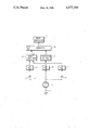
- FIGURE is a schematic block diagram of a correlation direction finder according to the invention.
- a correlation direction finder 1 is installed in a drop ammunition (not shown) to be dropped from a carrier aircraft or the like, for attacking armored vehicles.
- the drop ammunition rotates slowly about a vertical axis A and has a direction finding base b perpendicular to this axis A, with two microphones 2 and 3.
- the two microphones receive an acoustic signal radiated from the target with a time shift varying periodically.
- the time shift describes a sine, whose frequency is identical with the rotation frequency of the drop ammunition and whose amplitude depends, not only on the microphone spacing b and on the sound velocity, but also on the angle between the axis of rotation A and the direction of sound impingement.
- the time shift phase is determined by the rotational position of the direction finding base relative to the plane defined by the axis of rotation and the direction of sound impingement.
- the two microphone signals are preamplified in a signal processing stage 4 and 5, respectively, are frequency band limited, made white, hard limited, subsequently sampled and binary correlated to determine the time shift between the signals in a binary correlator 6.
- the correlation takes place within small angle sections along the circumferential angle of the rotating direction finding base b, during which the position of the direction finding base to the direction of sound impingement changes but little.
- the correlation and subsequent evaluation is clock-controlled, the clock signal being developed from the rotation frequency.
- a magnetic field sensor in this case a coil 7, which is mounted in the drop ammunition fixed in a vertical plane and whose diameter lies in the axis of rotation A. If the drop ammunition rotates about the axis A in the direction indicated by the arrow, coil 7 furnishes a sinusoidal output voltage, the frequency of which is identical with the rotation frequency of the drop ammunition.
- the output voltage is amplified in a signal processing circuit 8 and thereafter supplied to a phase locked frequency multiplier circuit 9. After appropriate signal processing, the output signal of the frequency multiplier circuit 9, is used as clock pulse signal for a microcomputer or computer 10.
- the size of the individual angle sections is established, within which the microphone signals are binary correlated.
- the microcomputer controls the binary correlator 6 in the same rhythm and takes over from it the correlation functions determined within the individual angle sections.
- the correlaction functions with their respective correlation peaks are stored in the microcomputer.
- the values of the correlation functions are weighted with a time factor.
- the now determined correlation functions of equal rotational sections are added to the stored and weighted correlation functions in the memory of the computer.
- the time curce of the correlation peaks during rotation of the drop ammunition describes, at constant rotation frequency, a sine.
- the time curve of the correlation peak position is subjected to a filtering process and thus smoothed to the expected sine curve. From this smoothed sine curve the target direction is then determined. At each zero passage the target direction is perpendicular to the direction finding base forming by the two microphones. The amplitude of this sine curve is more pronounced, the greater the angle is between the direction of the target and the axis of rotation of the drop ammunition. If the amplitude is zero, the drop ammunition points with the axis of rotation directly to the target. If this is not the case, the microcomputer 10 gives, based on the target direction determination, control signals to a drive control 11 of the drop ammunition.
- the drop ammunition comprises, e.g. distributed along its circumference, several drive mechanisms, e.g. gas generators, by means of which the drop ammunition can be displaced transversely when controlled accordingly. This takes place until the amplitude of the correlation peak curve has reached zero value.
- correlation direction finder described can be used also in connection with other applications and not only with a rotating drop ammunition.
Landscapes
- Physics & Mathematics (AREA)
- Engineering & Computer Science (AREA)
- General Physics & Mathematics (AREA)
- Radar, Positioning & Navigation (AREA)
- Remote Sensing (AREA)
- Measurement Of Velocity Or Position Using Acoustic Or Ultrasonic Waves (AREA)
Abstract
Description
Claims (8)
Applications Claiming Priority (2)
| Application Number | Priority Date | Filing Date | Title |
|---|---|---|---|
| DE3220175 | 1982-05-28 | ||
| DE3220175A DE3220175C2 (en) | 1982-05-28 | 1982-05-28 | Method and device for acoustic correlation direction finding |
Publications (1)
| Publication Number | Publication Date |
|---|---|
| US4577299A true US4577299A (en) | 1986-03-18 |
Family
ID=6164775
Family Applications (1)
| Application Number | Title | Priority Date | Filing Date |
|---|---|---|---|
| US06/497,201 Expired - Fee Related US4577299A (en) | 1982-05-28 | 1983-05-23 | Acoustic direction finder |
Country Status (3)
| Country | Link |
|---|---|
| US (1) | US4577299A (en) |
| DE (1) | DE3220175C2 (en) |
| FR (1) | FR2527784B1 (en) |
Cited By (6)
| Publication number | Priority date | Publication date | Assignee | Title |
|---|---|---|---|---|
| US4923155A (en) * | 1988-12-16 | 1990-05-08 | Andrew Dainis | Target support device for calibration of cameras |
| US5526433A (en) * | 1993-05-03 | 1996-06-11 | The University Of British Columbia | Tracking platform system |
| US20050249361A1 (en) * | 2004-05-05 | 2005-11-10 | Deka Products Limited Partnership | Selective shaping of communication signals |
| US20110110531A1 (en) * | 2008-06-20 | 2011-05-12 | Fraunhofer-Gesellschaft Zur Foerderung Der Angewandten Forschung E.V. | Apparatus, method and computer program for localizing a sound source |
| CN110501697A (en) * | 2018-05-17 | 2019-11-26 | 英飞凌科技股份有限公司 | Diversity sensing using different types of sensors |
| RU2848702C1 (en) * | 2025-04-18 | 2025-10-21 | Акционерное общество "Концерн "Центральный научно-исследовательский институт "Электроприбор" | Method for forming peiling relief at output of multi-element hydroacoustic antenna |
Citations (5)
| Publication number | Priority date | Publication date | Assignee | Title |
|---|---|---|---|---|
| US3838593A (en) * | 1972-11-06 | 1974-10-01 | Exxon Research Engineering Co | Acoustic leak location and detection system |
| US3870989A (en) * | 1970-03-16 | 1975-03-11 | Sanders Associates Inc | Underwater direction signal processing system |
| DE2131786A1 (en) * | 1971-06-26 | 1977-06-30 | Licentia Gmbh | Acoustic DF for underwater detection systems - has multiple detectors with linear combination matrix and dipole characteristic |
| US4236159A (en) * | 1975-02-03 | 1980-11-25 | The United States Of America As Represented By The Secretary Of The Navy | Passive direction finding system |
| US4425634A (en) * | 1980-08-26 | 1984-01-10 | Furuno Electric Co., Ltd. | Detection system |
-
1982
- 1982-05-28 DE DE3220175A patent/DE3220175C2/en not_active Expired
-
1983
- 1983-05-23 US US06/497,201 patent/US4577299A/en not_active Expired - Fee Related
- 1983-05-26 FR FR8308751A patent/FR2527784B1/en not_active Expired
Patent Citations (5)
| Publication number | Priority date | Publication date | Assignee | Title |
|---|---|---|---|---|
| US3870989A (en) * | 1970-03-16 | 1975-03-11 | Sanders Associates Inc | Underwater direction signal processing system |
| DE2131786A1 (en) * | 1971-06-26 | 1977-06-30 | Licentia Gmbh | Acoustic DF for underwater detection systems - has multiple detectors with linear combination matrix and dipole characteristic |
| US3838593A (en) * | 1972-11-06 | 1974-10-01 | Exxon Research Engineering Co | Acoustic leak location and detection system |
| US4236159A (en) * | 1975-02-03 | 1980-11-25 | The United States Of America As Represented By The Secretary Of The Navy | Passive direction finding system |
| US4425634A (en) * | 1980-08-26 | 1984-01-10 | Furuno Electric Co., Ltd. | Detection system |
Cited By (9)
| Publication number | Priority date | Publication date | Assignee | Title |
|---|---|---|---|---|
| US4923155A (en) * | 1988-12-16 | 1990-05-08 | Andrew Dainis | Target support device for calibration of cameras |
| US5526433A (en) * | 1993-05-03 | 1996-06-11 | The University Of British Columbia | Tracking platform system |
| US20050249361A1 (en) * | 2004-05-05 | 2005-11-10 | Deka Products Limited Partnership | Selective shaping of communication signals |
| US8275147B2 (en) | 2004-05-05 | 2012-09-25 | Deka Products Limited Partnership | Selective shaping of communication signals |
| US20110110531A1 (en) * | 2008-06-20 | 2011-05-12 | Fraunhofer-Gesellschaft Zur Foerderung Der Angewandten Forschung E.V. | Apparatus, method and computer program for localizing a sound source |
| US8649529B2 (en) | 2008-06-20 | 2014-02-11 | Fraunhofer-Gesellschaft Zur Foerderung Der Angewandten Forschung E.V. | Apparatus, method and computer program for localizing a sound source |
| EP2304969B1 (en) * | 2008-06-20 | 2015-10-14 | Fraunhofer Gesellschaft zur Förderung der angewandten Forschung e.V. | Apparatus, method and computer program for localizing a sound source |
| CN110501697A (en) * | 2018-05-17 | 2019-11-26 | 英飞凌科技股份有限公司 | Diversity sensing using different types of sensors |
| RU2848702C1 (en) * | 2025-04-18 | 2025-10-21 | Акционерное общество "Концерн "Центральный научно-исследовательский институт "Электроприбор" | Method for forming peiling relief at output of multi-element hydroacoustic antenna |
Also Published As
| Publication number | Publication date |
|---|---|
| FR2527784B1 (en) | 1986-01-17 |
| FR2527784A1 (en) | 1983-12-02 |
| DE3220175C2 (en) | 1985-05-02 |
| DE3220175A1 (en) | 1983-12-08 |
Similar Documents
| Publication | Publication Date | Title |
|---|---|---|
| US3953856A (en) | Method and apparatus for mapping and similar applications | |
| US6035257A (en) | Method and apparatus for reducing harmonic distortion | |
| Sathyaprakash et al. | Choice of filters for the detection of gravitational waves from coalescing binaries | |
| US5095467A (en) | Target tracking system for determining bearing of a target | |
| EP0988501B1 (en) | All-weather roll angle measurement for projectiles | |
| US4577299A (en) | Acoustic direction finder | |
| CA2026137C (en) | Procedure for determining the range and direction of sound-producing targets | |
| RU2352909C1 (en) | Method for radiolocating measurement of vessel hull vibration and device for its realisation | |
| US3680124A (en) | System for determining azimuth | |
| US3947803A (en) | Direction finding system | |
| RU2147136C1 (en) | Helicopter-borne radar system | |
| FR2417118A1 (en) | ANGULAR MEASUREMENT METHOD IN A TRACKING RADAR | |
| US3560973A (en) | Method and apparatus for passive mapping | |
| US3353487A (en) | Device for measuring flight distance of a missile | |
| US6424138B1 (en) | Spectrum analyzer utilizing a discontinuous signal record | |
| RU2180445C2 (en) | Method for construction of two-dimensional radar image of air target according to trajectory instabilities of its flight | |
| JP2610395B2 (en) | Helicopter guidance device | |
| EP0950165A1 (en) | Reticle for use in a guidance seeker for a spinning projectile | |
| WO1998031978A9 (en) | Reticle for use in a guidance seeker for a spinning projectile | |
| US5067096A (en) | Target engagement system for determining proximity to a target | |
| RU2017169C1 (en) | Method for remote measuring speed and direction of wind | |
| CA2046952C (en) | Measuring device | |
| RU2058033C1 (en) | Method for selecting moving targets | |
| US5559755A (en) | Range finding device and method | |
| RU2095824C1 (en) | Radar recognizing device |
Legal Events
| Date | Code | Title | Description |
|---|---|---|---|
| AS | Assignment |
Owner name: MESSERSCHMITT-BOLKOW-BLOHM GMBH, 8000 MUNCHEN 80, Free format text: ASSIGNMENT OF ASSIGNORS INTEREST.;ASSIGNORS:BLASCHKE, HANS P.;KNAPPIK, WINFRIED;METTE, HORST;AND OTHERS;REEL/FRAME:004145/0447 Effective date: 19830620 |
|
| FEPP | Fee payment procedure |
Free format text: PAYOR NUMBER ASSIGNED (ORIGINAL EVENT CODE: ASPN); ENTITY STATUS OF PATENT OWNER: LARGE ENTITY |
|
| FPAY | Fee payment |
Year of fee payment: 4 |
|
| AS | Assignment |
Owner name: LINC VENTURE LEASE PARTNERS II, L. P., ILLINOIS Free format text: SECURITY INTEREST;ASSIGNOR:POSITRON CORPORATION, A CORPORATION OF TX;REEL/FRAME:005856/0315 Effective date: 19910916 |
|
| AS | Assignment |
Owner name: VC ASSOCIATES, LTD., TEXAS Free format text: SECURITY INTEREST;ASSIGNOR:POSITRON CORPORATION, A CORPORATION OF TX;REEL/FRAME:005880/0647 Effective date: 19910916 Owner name: VENTEX PARTNERS, LTD. Free format text: SECURITY INTEREST;ASSIGNOR:POSITRON CORPORATION;REEL/FRAME:005870/0927 Effective date: 19910916 Owner name: HOUSTON VENTURE PARTNERS, LTD. Free format text: SECURITY INTEREST;ASSIGNOR:POSITRON CORPORATION, A CORP. OF TX;REEL/FRAME:005870/0732 Effective date: 19910916 Owner name: CONCORDE 1985 VENTURE INVESTORS Free format text: SECURITY INTEREST;ASSIGNOR:POSITRON CORPORATION, A CORP. OF TX;REEL/FRAME:005870/0693 Effective date: 19910916 Owner name: ENTERPRISE CAPITAL CORPORATION, TEXAS Free format text: SECURITY INTEREST;ASSIGNOR:POSITRON CORPORATION;REEL/FRAME:005870/0940 Effective date: 19910916 Owner name: SOVRAN FUNDING CORPORATION Free format text: SECURITY INTEREST;ASSIGNOR:POSITRON CORPORATION, A CORP. OF TX;REEL/FRAME:005870/0706 Effective date: 19910916 Owner name: RESEARCH DEVELOPMENT FOUNDATION Free format text: SECURITY INTEREST;ASSIGNOR:POSITRON CORPORATION, A CORP. OF TX;REEL/FRAME:005870/0719 Effective date: 19910916 |
|
| AS | Assignment |
Owner name: FINOVELEC, FRANCE Free format text: SECURITY INTEREST;ASSIGNOR:POSITRON CORPORATION, A TX CORPORATION;REEL/FRAME:005886/0536 Effective date: 19910916 Owner name: K. LANCE GOULD, M.D., TEXAS Free format text: SECURITY INTEREST;ASSIGNOR:POSITRON CORPORATION, A TX CORPORATION;REEL/FRAME:005886/0549 Effective date: 19910916 |
|
| FPAY | Fee payment |
Year of fee payment: 8 |
|
| REMI | Maintenance fee reminder mailed | ||
| LAPS | Lapse for failure to pay maintenance fees | ||
| FP | Lapsed due to failure to pay maintenance fee |
Effective date: 19980318 |
|
| STCH | Information on status: patent discontinuation |
Free format text: PATENT EXPIRED DUE TO NONPAYMENT OF MAINTENANCE FEES UNDER 37 CFR 1.362 |