US4576003A - Hybrid load-sense vehicle hydrostatic steering system - Google Patents
Hybrid load-sense vehicle hydrostatic steering system Download PDFInfo
- Publication number
- US4576003A US4576003A US06/713,085 US71308585A US4576003A US 4576003 A US4576003 A US 4576003A US 71308585 A US71308585 A US 71308585A US 4576003 A US4576003 A US 4576003A
- Authority
- US
- United States
- Prior art keywords
- fluid
- steering
- pilot
- control valve
- priority
- Prior art date
- Legal status (The legal status is an assumption and is not a legal conclusion. Google has not performed a legal analysis and makes no representation as to the accuracy of the status listed.)
- Expired - Lifetime
Links
Images


Classifications
-
- B—PERFORMING OPERATIONS; TRANSPORTING
- B62—LAND VEHICLES FOR TRAVELLING OTHERWISE THAN ON RAILS
- B62D—MOTOR VEHICLES; TRAILERS
- B62D5/00—Power-assisted or power-driven steering
- B62D5/06—Power-assisted or power-driven steering fluid, i.e. using a pressurised fluid for most or all the force required for steering a vehicle
- B62D5/09—Power-assisted or power-driven steering fluid, i.e. using a pressurised fluid for most or all the force required for steering a vehicle characterised by means for actuating valves
- B62D5/093—Telemotor driven by steering wheel movement
Definitions
- This invention relates to a load sense hydrostatic vehicle steering system that includes a fluid source which can deliver variable amounts of fluid (e.g., a variable displacement pump, a fixed displacement pump with a priority valve) and a hydrostatic steering controller which effects steering and also forms part of a pilot circuit for controlling the fluid flow delivered from the source.
- a fluid source which can deliver variable amounts of fluid (e.g., a variable displacement pump, a fixed displacement pump with a priority valve)
- a hydrostatic steering controller which effects steering and also forms part of a pilot circuit for controlling the fluid flow delivered from the source.
- a hydrostatic steering controller receives fluid from a pump, meters the fluid, and directs metered fluid to a steering motor to effect steering of the vehicle.
- the amount of fluid which is needed to effect steering depends on the rate at which the operator steers (operator demand) and the amount of resistance encountered by the vehicle's wheels (steering load).
- the operator is not steering, only a standby amount of fluid needs to be maintained in the steering circuit. Excess fluid, beyond that needed in the steering circuit, can be used for operating auxiliary devices on the vehicle.
- a priority valve operates to assure priority fluid flow to the steering circuit, and to direct excess fluid to an auxiliary circuit where it is available to operate auxiliary devices.
- the pump's maximum displacement is high enough to deliver more fluid flow and pressure than is necessary for making the most demanding of steering maneuvers.
- the pump displacement is reduced and/or the priority valve is positioned to reduce the amount of fluid in the steering circuit to a predetermined standby level.
- the pump displacement is increased, and/or the priority valve is positioned, to bring fluid flow and pressure in the steering circuit to levels which are sufficient to effect steering as demanded by the operator.
- U.S. Pat. Nos. 3,931,711 and 4,079,805 show load sense hydrostatic vehicle steering systems in which a hydrostatic steering controller effects steering of the vehicle and also forms part of a fluid control circuit which controls the displacement of a variable displacement pump.
- the fluid control circuit sets the displacement of the pump at a minimum level in which the pump maintains fluid in the steering circuit at a standby level.
- the fluid control circuit operates to increase pump displacement, when necessary, to insure that the fluid delivered from the pump will be sufficient to effect steering as demanded by the operator.
- the steering controller includes a steering control valve and a positive displacement metering unit.
- the controller has an inlet port which is connected to the variable displacement pump, and the steering control valve is biased to a neutral position in which it either totally blocks fluid at the controller's inlet port, or directs a small amount of pilot fluid to a reservoir.
- the controller is basically "closed center", when the steering control valve is in its neutral position. In response to a steering effort, the steering control valve moves away from its neutral position.
- the steering control valve After a predetermined range of movement away from its neutral position, the steering control valve reaches an operating condition in which it directs fluid from the controller's inlet port to the metering unit and directs metered fluid from the metering unit to the steering motor. More specifically, when the steering control valve reaches an operating condition, it establishes a main flow control orifice and directs fluid from the inlet port through the main flow control orifice to the metering unit.
- the steering control valve when the steering control valve is in an operating condition, the steering control valve has an operating range of movement (relative to the neutral position) in which the flow area of the main flow control orifice varies in accordance with the demand for fluid to effect steering.
- the flow area of the main flow control orifice varies directly with variations in (i) the rate at which the operator steers (operator demand) and/or (ii) the amount of resistance encountered by the vehicle's wheels (steering load).
- the steering control valve will move through its full operating range to a point at which the main flow control orifice will have a fixed, maximum flow area.
- a pressure signal taken from the downstream side of the variable main flow control orifice, is directed to a load sense port in the controller and used to control the displacement of the pump.
- the area of the main flow control orifice, and thus the pressure signal at the load sense port will vary in accordance with the operator's demand and the steering load.
- the pressure signal varies, it varies the displacement of the pump so that the pump delivers an appropriate amount of fluid to effect steering as demanded by the operator.
- a variable area orifice is provided in a pilot circuit which is in parallel with the main flow control orifice.
- the pilot circuit orifice also varies in area according to the operator demand and/or the steering load, at least over the operating range of the steering control valve.
- a pressure signal taken from one side of the pilot circuit orifice is directed to the load sense port of the controller and is used to control the displacement of the pump.
- a steering system may include from a variable displacement pump for directing fluid, through a priority valve, to a steering controller.
- the steering controller is basically "closed center", but does direct a small amount of pilot fluid to a reservoir, when there is no steering.
- a pilot fluid circuit originates outside the steering controller and communicates with the load sense port of the steering controller.
- the steering control valve directs the pilot fluid from the load sense port to the reservoir.
- Pressure signals taken at certain points in the pilot fluid circuit, act on the priority valve and on a flow compensator valve which controls the displacement of the pump. The pressure signals determine a standby position for the priority valve and a standby displacement for the variable displacement pump, in order to maintain standby levels of fluid in the system.
- the steering control valve when steering is initiated, the steering control valve abruptly restricts the pilot flow.
- the restriction occurs even before the valve reaches an operating condition in which it establishes the main flow control orifice that directs flow from the inlet port to the metering unit.
- the abrupt restriction of pilot flow produces a pressure spike in the pilot circuit.
- the pressure spike acts on the priority valve and on the flow compensator valve which controls the displacement of the pump to (i) urge the priority valve rapidly to its priority position and (ii) urge the flow compensator valve to a position in which the displacement of the pump increases.
- the pressure in the pilot circuit is controlled by the pressure at the downstream side of the main flow control orifice.
- the pressure at the downstream side of the main flow control orifice is used to control the position of the priority valve and the flow compensator valve in accordance with the operator's demand and the steering load.
- a variable displacement pump could have a very low displacement position when the system is in standby, and be brought up from its low displacement position when there is a need for flow and pressure in the steering circuit.
- variable displacement pumps react slowly when the system described above tries to bring them up from a very low displacement position.
- the inertia of the components which have to initially move in order to increase the pump's displacement, and thereafter the compressibility of the working fluid (e.g. oil), are the primary factors in delaying the pump's reaction time.
- some large area priority valves also have a high inertia, which can make it difficult to get the priority valves to respond to steering as quickly as is desirable. Since load sense systems are expected to react to steering demands in fractions of a second, a fluid source whose response is delayed for even a very small time beyond that which is intended may be unsuitable for use in a load sense system.
- This invention provides a hydrostatic vehicle load sense steering system which will improve the reaction of a source when an operator initiates a steering manuever.
- the system of the invention will provide a response that is improved beyond the type of response that can generally be attained by optimizing the components of the system for high inertia and fluid compressibility considerations.
- a main conduit communicates fluid to the inlet port of a steering controller, and a pilot circuit communicates pilot fluid to the load sense port of the controller.
- a pilot circuit communicates pilot fluid to the load sense port of the controller.
- the fluid at the controller's inlet port is blocked, and the fluid in the pilot circuit is directed to a reservoir.
- the system is designed so that it can come to a standby condition in which the amount of pilot fluid directed to the steering controller is high enough (e.g. 1 gal/min.) that it can be used to effect certain low demand steering maneuvers.
- the fluid source In producing the pilot flow, the fluid source will be in a "primed" condition, and there will be hydraulic fluid bias forces on the components of the source which have high inertia.
- the hydraulic fluid bias forces will bias the high inertia components in the direction they must move in order to further increase the fluid flow to the steering circuit.
- the controller signals the source to increase the fluid flow to the steering circuit, the hydraulic fluid bias forces on the high inertia components help the components move quickly to position(s) where the additional fluid flow is delivered to the steering circuit. The response of many sources whose components have a high inertia will thus be improved.
- the steering controller operates in a hybrid fashion, in the sense that it has an "open center" mode of operation for a range of low demand steering maneuvers and a "closed center” mode of operation for higher demand steering maneuvers.
- the pilot fluid alone may be sufficient to effect steering as demanded by an operator.
- the flow of pilot fluid to the reservoir is restricted, and pilot fluid is metered and directed to the steering motor to effect steering.
- the controller's main flow control orifice is open, there will not be any flow through it, since the pilot fluid is sufficient to effect steering.
- the system is operating in an "open center” mode.
- additional fluid flow must be directed from the inlet port to the metering unit in order to effect steering as demanded by the operator.
- the system operates with fluid from the inlet port in a "closed center” mode.
- the overall pressure-flow response of the source can be brought to acceptable levels.
- FIG. 1 is a schematic illustration of a load sense hydrostatic steering system according to the invention, showing the positions of the various components when there is no steering demand;
- FIG. 2 is a schematic illustration of the load sense hydrostatic steering system of the invention, showing the position of the various components during steering, as the steering control valve moves in its operating range;
- FIG. 2A is a fragmentary view of the system of FIG. 2, showing the flow in the steering controller upon initiation of steering, where there is a small demand for flow and pressure for steering, the steering control valve is in its operating range, and the pilot fluid is sufficient to satisfy the steering demand;
- FIG. 3 is a schematic illustration of the load sense hydrostatic steering system of the invention, showing the positions of the various components during steering, when there is a high demand for flow and pressure for steering, and the control valve has moved through its full operating range;
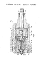
- FIG. 4 is a longitudinal sectional view of a hydrostatic load sense steering controller for use in a system according to the invention
- FIG. 5 is a fragmentary sectional view of a portion of the controller of FIG. 4, showing a side elevational view of a sleeve valve member in the controller;
- FIG. 6 is an end view of the sleeve valve member of FIG. 5 taken from the direction 6--6 of FIG. 5;
- FIG. 7 is a sectional view of the sleeve valve member of FIG. 6 taken along the section line 7--7 of FIG. 6;
- FIGS. 8 through 13 are sectional views of the sleeve valve member of FIG. 5 taken respectively along the sectional lines 8--8, 9--9, 10--10, 11--11, 12--12, and 13--13 of FIG. 5;
- FIG. 14 is a side elevational view of a rotatable spool valve member used in the controller of FIG. 4, taken from the direction 14--14 in FIG. 15;
- FIG. 15 is an enlarged sectional view of the spool valve member of FIG. 14 taken along the section line 15--15 of FIG. 14;
- FIG. 16 is a view of the gerotor gears forming the metering unit in a controller for use in a system according to the invention.
- FIG. 17 is a fragmentary schematic view of a section of the control valve in the steering controller, when the system is in the condition of FIG. 1;
- FIG. 18 is a fragmentary schematic plan view of a part of the control valve spool in the steering controller, when the control valve is in the position of FIG. 17;
- FIG. 19 is a fragmentary schematic view of a section of the control valve in the steering controller, when the system is in the condition of FIG. 2;
- FIG. 20 is a fragmentary schematic plan view of a part of the control valve spool in the steering controller, when the control valve is in the position of FIG. 19;
- FIG. 21 is a fragmentary schematic view of a section of the control valve in the steering controller, when the system is in the condition of FIG. 3;
- FIG. 22 is a fragmentary schematic plan view of a part of the control valve spool in the steering controller, when the control valve is in the position of FIG. 21.
- a vehicle steering system includes a variable displacement pump 10 which is driven by an input shaft 12. Fluid delivered from the pump 10 is directed through a priority valve 28 to a steering circuit 17. Excess fluid, beyond that needed in the steering circuit 17, is directed by the priority valve 28 to an auxiliary circuit 30 where the fluid is available to operate one or more auxiliary devices carried on the vehicle.
- the steering circuit 17 includes a steering motor 24, which is connected to the vehicle's wheels 14, and a hydrostatic steering controller 16 which controls fluid to operate the steering motor 24.
- the hydrostatic steering controller 16 includes a control valve 20 and a positive displacement metering unit 22 which are operated by rotation of the vehicle's steering wheel 18. When the steering wheel 18 is rotated, the controller 16 meters fluid and directs the metered fluid to one chamber of the steering motor 24, while connecting the other chamber of the steering motor 24 to a reservoir 26. As the steering motor 24 is operated, it effects turning of the vehicle's wheels 14 in a manner which is well known, and need not be further described.
- the pump 10 is preferably an axial piston pump with a swash plate 72 which determines the length of stroke of a series of pistons 73.
- the swash plate 72 can pivot relative to a central axis 74 in order to vary the length of stroke of the pistons 73, and thereby vary the displacement of the pump.
- the swash plate 72 is biased by a spring 76 toward the position shown in FIG. 3.
- the swash plate 72 can pivot in the direction shown by the arrow in FIG. 2 to reduce the displacement of the pump. Theoretically, it could pivot to a point at which the pump's displacement is as low as possible, yet the pump delivers a small standby amount of fluid to the system.
- Such a swash plate position is referred to as the minimum displacement position and is represented in phantom at 21 in FIG. 1.
- the swash plate 72 has what may be termed intermediate positions. In its intermediate positions, the swash plate sets the displacement of the pump above its minimum level and below its maximum level.
- the position of the swash plate 72 depends upon the force of spring 76 and the pressure in a fluid chamber 80 formed on one side of a hydraulic fluid actuator 78.
- the spring 76 forces the swash plate 72 to the position of FIG. 3 to set the pump 10 in its maximum displacement position.
- the swash plate 72 is shifted away from its maximum displacement position (in the direction shown by the arrow in FIG. 2) to reduce the pump's displacement.
- the pressure in the chamber 80, and thus the displacement of the pump 10, is controlled by a valve arrangement comprising a flow compensator valve 82 and a pressure compensator valve 84.
- the flow compensator valve 82 includes a valve element 86 which is biased by a spring 88 toward the position shown in FIG. 3. In the position of FIG. 3, the flow compensator valve element 86 communicates the fluid chamber 80 to the reservoir 26, by communicating a cavity 85, which is connected to chamber 80, to the reservoir 26. Fluid pressure from the outlet of the pump is communicated to a chamber 89 on one side of the valve element 86 and acts against one end surface 90 of the valve element 86.
- Fluid pressure in a pilot conduit 59 (described more fully hereinafter) is communicated to a spring chamber 92 and acts on the opposite end surface 93 of the valve element 86.
- the valve element 86 When the net fluid pressure force on the valve element 86 exceeds the force of spring 88, the valve element 86 is shifted rightwardly from the position of FIG. 3.
- the valve element When the valve element shifts rightwardly from the position shown in FIG. 3, it communicates fluid from the fluid chamber 89 to the fluid chamber 80.
- the fluid acts on the actuator 78 to shift the swash plate 72 in the direction shown by the arrow in FIG. 2 to reduce the displacement of the pump.
- the pump 10 is preferably a 2.77 CID variable displacement, axial piston pump, manufactured by The Cessna Aircraft Company, Wichita, Kans.
- the spring 76 urges the swash plate 72 toward its maximum displacement position (FIG. 3).
- the pumping action of the pistons 73 produces a net moment M (FIG. 1) on the swash plate 72, which also biases the swash plate 72 in a direction which increases the pump displacement.
- FIGS. 1 see in FIGS.
- the spring 76 might not be able to drive the swash plate 72 fast enough to increase the pump's displacement fast enough to make the pump acceptable for many load sense systems. Additionally, if the working fluid is not delivered immediately, the compressibility of the fluid can result in pump pressure still not increasing in accordance with demand.
- the pump's displacement will be above the minimum level (but well below the maximum level).
- the length of stroke of the pistons 73 will be increased, the pump's outlet pressure response will be increased, and the net moment M (FIG. 1) produced by the pistons 73 on the swash plate 72 will thereby be increased.
- the increased moment M would assist the spring 76 in rapidly moving the swash plate 72 to a position in which the pump's displacement is increased further.
- the fluid delivered by the pump 10 is directed to the priority valve 28.
- the priority valve 28 directs priority fluid flow to the steering circuit 17 and excess fluid flow, beyond that needed in the steering circuit 17, to the auxiliary circuit 30.
- the fluid directed to the auxiliary circuit 30 can be used to operate one or more auxiliary devices on the vehicle.
- the priority valve 28 includes ahousing 33, which defines an elongated chamber 34, and a valve element 36 which is axially movable in the chamber 34.
- the housing 33 has (i) an annular inlet cavity 38 which receives fluid from the pump 10, (ii) an annular priority outlet cavity 40 which communicates (through a priority port 42 and a one-way check valve 39) with the steering circuit 17, and (iii) an annular auxiliary outlet cavity 44 which communicates with the auxiliary circuit 30.
- Each of the cavities 38, 40, and 44 encircles the chamber 34 and is spaced along the chamber from the other cavities.
- the valve element 36 operates to control flow from the inlet cavity 38 and direct it to the priority outlet cavity 40 and/or the auxiliary outlet cavity 44.
- the valve element 36 is biased by a spring 43 toward a priority position (FIG. 3) in which there is no flow from the pump 10 to the auxiliary circuit. Thus, all flow from the pump 10 is made available to the steering circuit 17.
- the priority valve element 36 can move away from its priority position and direct excess flow, i.e., beyond that needed for steering, to the auxiliary circuit 30.
- the valve element 36 can move away from its priority position when a fluid pressure force which acts on the valve element 36 exceeds the force of the spring 43.
- the fluid pressure in the priority outlet cavity 40 acts on the surfaces 41 and 47 at one end of the valve element 36.
- Fluid pressure at a point in the pilot fluid circuit (described more fully hereinafter) is communicated to a spring cavity 45, and acts on the surfaces 53, 55 at the other end of the valve element 36.
- fluid pressures in the cavities 40 and 45 act on opposite ends of the valve element 36, and produce a net fluid pressure force of the valve element 36.
- valve element 36 When the net fluid pressure force on the valve element 36 exceeds the force of the biasing spring 43, the valve element 36 will move away from the priority position (i.e., rightwardly from the positioning FIG. 3). As it moves away from the priority position, the valve element 36 will (i) gradually decrease communication between the inlet 38 and the priority outlet cavity 40 and (ii) establish and gradually increase communication between the inlet 38 and the auxiliary cavity 44. In the priority valve 28, a relief valve 35 operates to relieve excess fluid pressure in spring cavity 45 to the reservoir 26.
- a main fluid conduit 57 communicates fluid from the priority outlet port 42 to a main inlet port 50 of the steering controller.
- a pilot conduit system described more fully hereinafter, directs pilot fluid to a load sense port 58 of the steering controller.
- the metering unit 22 and the control valve 20 are disposed within a housing 49.
- the steering controller's housing 49 includes the inlet port 50, load sense port 58, two working ports 52, 54 connected to opposite chambers of the steering motor 24, and a return port 56 connected to the reservoir 26.
- An input member 102 which is connected to the steering wheel 18, extends into the housing 49 and is supported for rotation about a central axis 104.
- the metering unit 22 and the control valve 20 are connected with the input member 102 and are operated by rotation of the input member 102 about the central axis 104.
- the metering unit 22 is constructed according to the principles disclosed in U.S. Pat. No. 3,895,888. It includes a gerotor gear mechanism comprising an outer gear 106 haing a series of internal teeth, and an inner gear 108 with external teeth numbering one less than the number of teeth of the outer gear 106 (see FIG. 16).
- the outer gear 106 is fixed, by bolts 107, to a drive plate 109 which is fixed to the input member 102.
- the inner gear 108 is mounted eccentrically with respect to the outer gear 106, and is adapted to rotate about its central axis and to orbit relative to the outer gear 106.
- the inner and outer gears 108, 106 define fluid pockets which expand and contract as the gears rotate and orbit relative to each other.
- a commutation valve arrangement controls flow to and from the expansible and contractible pockets in timed relation to the relative rotational and orbital movement of the gears.
- the commutation valve arrangement includes an outer member 110 which is bolted to and rotates with the outer gear 106, and an inner member 112 which can rotate with the inner gear 108.
- the outer commutator member 110 has a number of fluid passages, equal to the number of teeth in the outer gear 106. While the passages are not shown in FIG.
- the inner commutator valve member 112 has an array of fluid openings equal to twice the number of teeth on the inner gerotor gear 108.
- the array of fluid openings includes (i) radial openings 113 which communicate with a central opening 115 in the valve member 112 and (ii) axial openings 117 which communicate with a fluid space 119 adjacent one end of the control valve 20.
- the radial openings 113 and the axial openings 115 are alternately spaced about the outer periphery of the inner commutator valve member 112. Commutation valving occurs at the interface of the commutator valve members 110, 112, when the valve members rotate relative to each other.
- the control valve 20 includes a part of the housing 49, a valve sleeve 114 which is fixed in the housing, and a rotatable control valve spool 116.
- the rotatable spool 116 is connected with the inner commutator valve member 112 (through an element 118), so that the spool 116 and the inner commutator valve member 116 can rotate jointly.
- An angular drive link 120 couples the inner gerotor gear 108 for joint rotation with the inner commutator valve member 112, thus also coupling the inner gerotor gear 108 for joint rotation with the rotatable control valve spool 116.
- a longitudinally extending torsion spring 122 biases the rotatable control valve spool 116 to a neutral position.
- the torsion spring 122 has a first end connected to the rotatable control valve spool 116 and a second end connected to a plug 124 which is fixed in the housing 49.
- the torsion spring 122 comprises a pair of blades constructed according to the principles of U.S. Pat. No. 3,918,856.
- the controller has a "closed-center" mode of operation, in terms of the way it utilizes fluid from the inlet port 50 to operate the steering motor 24. Specifically, when the control valve spool 116 is in its neutral position (FIG. 1), it blocks fluid flow from the controller's inlet port 50 to the metering unit 22. Also, when the control valve spool 116 is in its neutral position, the metering unit is in a "lock-up" condition in which the gerotor gears 106, 108 can rotate jointly, but the inner gear 108 cannot orbit.
- the inner gear member 108 of the metering can orbit as the outer gear 106 rotates, in order to meter fluid.
- the control valve spool 116 directs the metered fluid to the steering motor 24 to operate the steering motor 24.
- a fluid reaction force from the steering motor i.e., the steering load
- the fluid which is directed to the metering unit assists the metering unit in overcoming the steering load to effect steering.
- the steering circuit 117 is in a condition in which the steering demand is being satisfied.
- the amount of fluid directed to the metering unit is not sufficient to enable the inner gear 108 to orbit only, the metering unit will again be in a "lock-up" condition, and will cause the control valve spool 116 to move further away from its neutral position, to increase the area of the main flow control orifice 60 communicating the inlet port 50 with the metering unit. Additional fluid will be directed from the inlet port 50 to the metering unit 22 to help the system satisfy the steering demand.
- the control valve spool 116 when an operator steers, if the metering unit is not receiving sufficient fluid to enable it to reach a condition in which the steering demand is being satisfied, it will be in its "lock-up" condition, and the control valve spool 116 will move further from its neutral position until either (i) the system reaches a steady-state condition in which the steering demand is being satisfied or (ii) the control valve spool 116 moves to the limit of its range of movement away from the neutral position. At a predetermined high steering demand, the control valve spool reactes the limit of its range of travel away from the neutral position. In that position (FIG. 3), the flow area of orifice 60 is a maximum. In the controller of FIG. 4, the control valve spool's range of movement, relative to the neutral position, is defined by a lug 126 which is carried on the inner commutator valve element 112, and which can move to a limited extent in a slot 128 formed in the housing.
- control valve spool 116 will shift back toward its neutral position under (i) the influence of the torsion spring 122 and (ii) the follow-up action of the metering unit 22. If steering effort ceases, the control valve spool 116 will return to its neutral position.
- a first pilot conduit 46 branches from the priority outlet cavity 40 of the priority valve. It communicates, through a fixed area orifice 48, with a conduit 59 leading to the load sense port 58 of the steering controller.
- a second pilot conduit 62 also branches from the priority outlet cavity 40. It communicates with the priority valve's spring cavity 45 through a fixed area orifice 64. The spring cavity 45 communicates, in turn, with the conduit 59, through another fixed area orifice 66.
- the pilot circuit extending between the priority outlet cavity 40 and the conduit 59 includes a pair of pilot conduits 46 and 62 which are in parallel with each other.
- control valve spool 116 when the control valve spool 116 is in its neutral position, it directs pilot fluid from the load sense port 58 to the reservoir 26 (see FIG. 1).
- the pilot fluid is directed to the reservoir 26 through (i) a first fixed area orifice 68 and (ii) a second variable area orifice 70 formed partially by the control valve spool 116.
- the variable area orifice 70 When the control valve 20 is in its neutral position, the variable area orifice 70 has its maximum flow area.
- the pump 10 when there is no steering, and the control valve spool 116 is in its neutral position (FIG. 1), the pump 10 will be in an intermediate displacement which is (i) above its minimum displacement condition (21 in FIG. 1) and (ii) below its maximum displacement condition. Further, the priority valve element 36 will be in a position in which it maintains a certain pilot flow (i.e. about 1 gal/min) in the pilot circuit. Specifically, in the pilot circuit, the orifice 48 is relatively large in area, and the bulk of the pilot flow is directed through the orifice. The series arrangement of orifices 64 and 66 directs a small portion of the pilot flow through the spring cavity 45 of the priority valve 28.
- a certain pilot flow i.e. about 1 gal/min
- the pilot orifice system (orifices 48, 64, 66, 68, 70) is specifically sized, in relation to (i) the biasing spring 43 acting on the priority valve 36, (ii) the spring 88 which biases the flow compensator valve 86, and (iii) the spring 76 which biases the swash plate 72, so that when there is no steering the system can come to a steady-state standby condition in which a predetermined pilot flow (e.g. 1 gal/min) will be directed through the control valve spool 116 and to the reservoir 26.
- the pilot orifice system is designed so that the system cannot come to a steady-state condition when there is no steering until the predetermined pilot flow is being directed to the reservoir.
- the fixed area orifice 68 performs a stabilizing function, to minimize the effect of unintended pressure fluctuations in the pilot conduit 59 on the controller 16.
- the relatively high pilot flow will cause the pressure in cavity 80 to be lower when the system comes to a steady-state cnndition than it would be if the pilot flow were at a minimum level (e.g., 0.25 gal/min.).
- a minimum level e.g. 0.25 gal/min.
- the steady-state standby pilot fluid flow directed through the controller to the reservoir is sufficient to perform same low demand steering maneuvers (e.g., the operator steers gradually).
- the steering system can operate in an "open-center” mode, utilizing the pilot fluid alone to satisfy the steering demand.
- the pilot fluid flow is not large enough to handle higher steering demands, and the steering controller maintains its "closed center” mode of operation in handling higher steering demands, as discussed more fully hereinafter.
- control valve spool 116 During steering, as the control valve spool 116 moves away from its neutral position and toward its operating condition, it also begins (i) restricting pilot flow to the reservoir 26 and (ii) directing pilot fluid to the metering unit 22 (FIG. 2).
- the rate at which the flow of pilot fluid to the reservoir 26 is restricted, and the flow to the metering unit 22 increased, is correlated to the flow controlling components of the system so that over at least part of the operating range of the control valve spool 116, the pilot fluid alone may be able to satisfy the steering demand.
- the flow of pilot fluid to the reservoir is restricted by orifice 70 at a rate such that if the control valve spool 116 is operating over an initial part of its operating range, the amount of pilot fluid being directed to the metering unit 22 may equal the rate at which metered fluid is being directed to the steering motor.
- flow via control orifice 60 is not required, and there may not be any flow through it, as shown schematically in FIG. 2A.
- the system will still be operating "closed center" as to the fluid communicated to the inlet port 50, because there is no flow through the inlet port.
- the orifice 70 and the priority valve element 36 can modulate flow and pressure in the pilot circuit, so that the pump's displacement will remain essentially unchanged.
- control valve spool 116 moves through the remainder of its operating range, indicating a higher steering demand, there will be flow through the main flow control orifice 60 to the metering unit, and the pressure at the load sense port 58 will vary directly in accordance with variations in the flow through the main flow orifice 60. As the flow area of the orifice 60 varies, it will vary the pressure signal at the load sense port 58. The displacement of the pump and/or the position of the priority valve will change, as necessary, in order to try to bring the system to a steady-state condition in which the fluid being directed to the metering unit is sufficient to effect steering as demanded by the operator.
- the control valve spool 116 moves further away from its neutral position, there will be an increased pressure in the pilot conduit 59.
- the increased pressure will increase the pressure fluid force which acts on the priority valve element 36 together with the force of biasing spring 43 and biases the priority valve element 36 toward its priority position.
- the increased pressure will require the system pressure to elevate to a higher level before it can shift the priority valve element 36 away from its priority position.
- the increased pressure in the pilot conduit 59 will be transmitted to the spring cavity 92 of the flow compensator valve 82, so that the pressure in the cavity 92 reflects the demand condition of the steering circuit.
- the control valve spool 116 moves rapidly away from its neutral position, and abruptly closes the pilot orifice 70. Closing the pilot orifice creates a pressure surge in the pilot conduit 59. This surge is controlled by the rate at which the flow of pilot fluid is restricted, and the rate at which flow through the metering unit 22 and to the steering motor is increased. This, the valve timing should be such that the surge will be primarily provided in the conduit 59, and will not be unduly dissipated by connection to the load. With proper timing the pressure surge generated in the conduit 59 rapidly drives the priority valve element 36 toward its priority position to insure priority flow for steering.
- the pressure surge will also rapidly drives the flow compensator valve to the position shown in FIG. 3.
- the fluid cavity 80 is vented to the reservoir 26, and the combination of the spring 76 and the biasing moment M drives the swash plate 72 in a direction which rapidly increases the pump's displacement.
- the basic valving for the closed center mode of operation incorporates the principles of U.S. Pat. No. 3,895,888 and U.S. application Ser. No. 243,497, which are assigned to the assignee of this application and which are incorporated herein by reference.
- the flow from the inlet port 50 to the metering unit 22 and from the metering unit 22 to the steering motor 24 is controlled by the control valve spool 116.
- the housing 49 includes an annular groove 130 connected with the inlet port 50, another annular groove 132 connected with the return port 56, two annular grooves 134, 136 connected to the working ports 52, 54, and an annuar groove 138 connected with the load sense port 58.
- the fixed valve sleeve 114 includes a series of longitudinal grooves and radial passages for directing fluid between the various ports and the metering unit. Specifically, as seen in FIG. 17, the fixed valve sleeve 114 has (i) longitudinal grooves P connected, via annular groove 130, with the inlet port 50, (ii) longitudinal grooves C 1 , C 2 connected via annular grooves 134, 136, with respective working ports 52, 54, and (iii) longitudinal grooves LS connected, via annular groove 138, with the load sense port 58.
- the fixed valve sleeve 114 and (i) passages R extending radially therethrough and connected, via annular groove 132, with the return port 56, and (ii) radial passages 133 connected to one side of the metering unit (through the fluid space 119 and the commutator valve).
- the fixed valve sleeve 114 includes diametrically opposed radial passages PD which are (i) spaced axially from the radial passages R shown in FIG. 5 and (ii) communicated, via the annular groove 138, with the load sense port 58.
- the rotatable control valve spool 116 (FIGS. 14, 15, 17-22) includes a plurality of longitudinal grooves 143, 150, 152, 154 which extend to its outer periphery, and a longitudinally extending central passage 144 coaxial with the spool.
- the central passage 144 is connected to the longitudinal grooves 143 via radial passages 146 (FIG. 4).
- the central passage 144 is also in fluid communication with the central opening 115 in the inner commutator valve member 112.
- Certain of the longitudinal grooves 150 face the LS grooves in the fixed valve sleeve 114 and are blocked from communication with the inlet grooves P, when the valve spool 116 is in its neutral position (see FIG. 17).
- valve spool 116 When the valve spool 116 is rotated in one direction (i.e., counterclockwise in from the position of FIG. 17), beveled longitudinally extending surfaces 151 on the grooves 150 underlap the inlet grooves P.
- the inlet port 50 then communicates with the metering unit through (i) the bevelled surfaces 151 and the grooves 150 in the valve spool 116, (ii) the LS grooves in fixed valve sleeve 114, (iii) longitudinal grooves 152 in the valve spool 116, (iv) the radial passages 133 in the fixed valve sleeve 114, (v) the fluid space 119, (vi) the axial openings 117 in the inner commutator valve member 112, and (vii) certain of the passages in the outer commutator valve member 110.
- the beveled surfaces 151 cooperate with the fixed valve sleeve 114 to form the variable area orifice 60 shown in FIGS. 2 and 3.
- one set of cylinder grooves (i.e., C 1 ) communicates with the reservoir 26 through (i) the longitudinal grooves 154 formed in the rotatable valve spool 116 and (ii) some of the radial passages R in the fixed valve member 114.
- the other set of cylinder grooves C 2 receive metered fluid via (i) certain of the passages in the outer commutator valve member 110, (ii) the radial openings 113 in the inner commutator member 112, (iii) the central opening 115 in the commutator valve member 112, (iv) the central passage 144 in the valve spool 116 and (v) the grooves 143 in the valve spool 116 which face the cylinder grooves C 2 .
- valve spool 116 When the valve spool 116 rotates counterclockwise from the position shown in FIG. 17, it moves from the position shown in FIGS. 17, 18 to the position shown in FIGS. 19, 20 and toward its operating condition.
- Its operating range i.e., the range in which the orifice 60 will vary in size according to the operator's demand and the steering load, is the range of movement of the valve spool 116 between the position shown in FIGS. 19, 20 and the position shown in FIGS. 21, 22.
- the valve spool 116 moves through its full operating range, it will be in the position shown in FIGS. 21, 22. In position of FIGS. 21, 22, the flow area of orifice 60 (i.e., the flow area from grooves P, across bevelled surfaces 151 and to the metering unit) is at a maximum value.
- valve spool 116 shifts clockwise from the position of FIG. 17, then the valving of fluid is by similar principles, but the flow through the metering unit is reversed.
- the fluid from the inlet grooves P is directed to the metering unit via (i) grooves 143, (ii) radial passages 146, and (iii) central passage 144 in the movable valve spool 116.
- Metered fluid is directed to the cylinder grooves C 1 via (i) radial passages 133 in the valve sleeve 114, and (ii) longitudinal grooves 152 in the valve spool 116.
- control valve spool 116 (i) directs the pilot flow of fluid to the return port 26 when the control valve spool 116 is in the neutral position, and (ii) restricts the flow of pilot fluid to the reservoir 26 as the control valve spool 116 moves toward its operating condition and over a portion of its operating range.
- the longitudinal grooves 150 have axially projecting narrow longitudinal extensions 150' (see FIGS. 18, 20, 22).
- the load sense port 58 is continuously communicated with the LS grooves in the fixed valve sleeve 114 through the fixed area orifice 68 (shown in FIGS. 1-4).
- Certain of the radial passages R in the fixed valve sleeve 114 have restricted outlets R 1 which are communicated with the narrow extensions 150' when the valve spool 116 is in its neutral condition (FIGS. 17, 18).
- the longitudinal extensions 150' and the restricted outlets R 1 form the orifice 70 shown schematically in FIGS. 1, 2.
- valve spool 116 When the valve spool 116 rotates counterclockwise from the position shown in FIG. 17, the longitudinal extensions 150' move relative to the restricted outlets R 1 and the flow of pilot fluid to the reservoir 26 is restricted. At the point where the control valve spool 116 reaches its operating condition (FIG. 19), the amount of restriction is significant, and causes a pressure increase in the pilot conduit 59. Also, when the control valve spool 116 reaches an operating condition, the LS grooves are connected to the intake side of the metering unit, so that pilot fluid which is not directed to the reservoir is now directed to the metering unit.
- the valve spool 116 moves farther from its neutral position. As it moves farther from the neutral position, the communication between the narrow extensions 150' and the restricted outlets R 1 decreases, thus further increasing the pressure in the LS cavity and thereby in the pilot conduit 59.
- the valving is designed so that communication between the narrow extensions 150' and the restricted outlets R 1 will begin closing when the control valve spool 116 initially moves away from its neutral position and will increasingly close as the valve spool 116 moves through at least part of its operating range. When the control valve spool 116 has moved through its full operating range, the communication between the narrow extensions 150' and the restricted outlets R 1 will be completely closed (FIGS. 21, 22).
- the communication between the narrow extensions 150' and the restricted openings R 1 will rapidly close, providing a pressure surge in the pilot conduit 59.
- the pressure surge will be transmitted to the spring cavity 45 of the priority valve and to the spring cavity 92 of the flow compensator valve 82. It will rapidly urge the priority valve element 36 toward its priority position, and will rapidly urge the flow compensator valve element 86 toward a position in which the fluid chamber 80 is vented to the reservoir.
- the hydraulic moment M which is already acting on the swash plate 72 due to the relatively high pilot flow will assist the spring 76 in rapidly urging the swash plate 72 toward the maximum displacement position for the pump.
- the system will respond rapidly to such a steering demand.
- the flow of pilot fluid in conduit 59 may be augmented by a pilot fluid signal from the auxiliary circuit 30, in accordance with the principles of U.S. application Ser. No. 345,546, now U.S. Pat. No. 4,454,716, which is assigned to the assignee of this invention and which is incorporated herein by reference.
- the auxiliary circuit 30 may include one or more load sense valves which can produce a pressure signal in an auxiliary load sense conduit 169 when there is a need for additional fluid in the auxiliary circuit 30.
- the load sense signal from the auxiliary circuit is communicated from the auxiliary conduit 169 through a check valve 173 and to the spring cavity 92 of the flow compensator valve 82, so that the pressure in the spring cavity 92 reflects the auxiliary circuit's need for fluid.
- the flow compensator valve 82 can cause the pump displacement to vary accordingly.
- an auxiliary pilot orifice 170 connects the auxiliary load sense conduit 169 to the pilot conduit 59, and forms a common bleed orifice for the auxiliary circuit, as discussed in application Ser. No. 345,546 now U.S. Pat. No. 4,454,716.
- a one-way check valve 172 which communicates the pilot conduit 59 with the spring cavity 92 of the flow compensator valve 82.
- the arrangement of orifice 170 and check valve 172 has the effect of increasing the pressure in the pilot conduit system when an auxiliary device is operating and improving the speed with which the system can react to a steering effort when an auxiliary device is operating. Also, by relocating the orifice 170 and check valve assembly 172 so that it connects to the conduit 59 at a location downstream of the parallel pilot conduits 46, 62, it may be possible to eliminate the stabilizing orifice 68 in the controller 16.
Abstract
Description
Claims (11)
Priority Applications (1)
| Application Number | Priority Date | Filing Date | Title |
|---|---|---|---|
| US06/713,085 US4576003A (en) | 1982-10-29 | 1985-03-18 | Hybrid load-sense vehicle hydrostatic steering system |
Applications Claiming Priority (2)
| Application Number | Priority Date | Filing Date | Title |
|---|---|---|---|
| US43763382A | 1982-10-29 | 1982-10-29 | |
| US06/713,085 US4576003A (en) | 1982-10-29 | 1985-03-18 | Hybrid load-sense vehicle hydrostatic steering system |
Related Parent Applications (1)
| Application Number | Title | Priority Date | Filing Date |
|---|---|---|---|
| US43763382A Continuation | 1982-10-29 | 1982-10-29 |
Publications (1)
| Publication Number | Publication Date |
|---|---|
| US4576003A true US4576003A (en) | 1986-03-18 |
Family
ID=27031386
Family Applications (1)
| Application Number | Title | Priority Date | Filing Date |
|---|---|---|---|
| US06/713,085 Expired - Lifetime US4576003A (en) | 1982-10-29 | 1985-03-18 | Hybrid load-sense vehicle hydrostatic steering system |
Country Status (1)
| Country | Link |
|---|---|
| US (1) | US4576003A (en) |
Cited By (4)
| Publication number | Priority date | Publication date | Assignee | Title |
|---|---|---|---|---|
| US4862690A (en) * | 1988-10-06 | 1989-09-05 | Eaton Corporation | Steering control unit with both flow amplification and manual steering capability |
| US6065561A (en) * | 1998-11-23 | 2000-05-23 | Howard; Durrell U. | Power steering system with controlled centering |
| US20030005820A1 (en) * | 2001-07-03 | 2003-01-09 | Hudson Michael D. | Hydraulic system with flow priority function |
| US20050000750A1 (en) * | 2003-06-23 | 2005-01-06 | Toyoda Koki Kabushiki Kaisha | Flow controlling apparatus for power steering |
Citations (7)
| Publication number | Priority date | Publication date | Assignee | Title |
|---|---|---|---|---|
| US3931711A (en) * | 1974-11-06 | 1976-01-13 | Trw Inc. | Controller assembly |
| US4011721A (en) * | 1976-04-14 | 1977-03-15 | Eaton Corporation | Fluid control system utilizing pressure drop valve |
| US4043419A (en) * | 1976-06-04 | 1977-08-23 | Eaton Corporation | Load sensing power steering system |
| US4079805A (en) * | 1974-11-06 | 1978-03-21 | Trw Inc. | Vehicle steering system |
| US4096883A (en) * | 1976-08-24 | 1978-06-27 | Eaton Corporation | Closed-center controller and neutral bypass arrangement therefor |
| US4167893A (en) * | 1978-02-06 | 1979-09-18 | Eaton Corporation | Load sensing valve |
| US4337620A (en) * | 1980-07-15 | 1982-07-06 | Eaton Corporation | Load sensing hydraulic system |
-
1985
- 1985-03-18 US US06/713,085 patent/US4576003A/en not_active Expired - Lifetime
Patent Citations (7)
| Publication number | Priority date | Publication date | Assignee | Title |
|---|---|---|---|---|
| US3931711A (en) * | 1974-11-06 | 1976-01-13 | Trw Inc. | Controller assembly |
| US4079805A (en) * | 1974-11-06 | 1978-03-21 | Trw Inc. | Vehicle steering system |
| US4011721A (en) * | 1976-04-14 | 1977-03-15 | Eaton Corporation | Fluid control system utilizing pressure drop valve |
| US4043419A (en) * | 1976-06-04 | 1977-08-23 | Eaton Corporation | Load sensing power steering system |
| US4096883A (en) * | 1976-08-24 | 1978-06-27 | Eaton Corporation | Closed-center controller and neutral bypass arrangement therefor |
| US4167893A (en) * | 1978-02-06 | 1979-09-18 | Eaton Corporation | Load sensing valve |
| US4337620A (en) * | 1980-07-15 | 1982-07-06 | Eaton Corporation | Load sensing hydraulic system |
Cited By (7)
| Publication number | Priority date | Publication date | Assignee | Title |
|---|---|---|---|---|
| US4862690A (en) * | 1988-10-06 | 1989-09-05 | Eaton Corporation | Steering control unit with both flow amplification and manual steering capability |
| US6065561A (en) * | 1998-11-23 | 2000-05-23 | Howard; Durrell U. | Power steering system with controlled centering |
| US20030005820A1 (en) * | 2001-07-03 | 2003-01-09 | Hudson Michael D. | Hydraulic system with flow priority function |
| US6769348B2 (en) * | 2001-07-03 | 2004-08-03 | Caterpillar Inc | Hydraulic system with flow priority function |
| US20050000750A1 (en) * | 2003-06-23 | 2005-01-06 | Toyoda Koki Kabushiki Kaisha | Flow controlling apparatus for power steering |
| US7124855B2 (en) * | 2003-06-23 | 2006-10-24 | Toyoda Koki Kabushiki Kaisha | Flow controlling apparatus for power steering |
| CN100377950C (en) * | 2003-06-23 | 2008-04-02 | 株式会社捷太格特 | Flow controlling apparatus for a power steering system |
Similar Documents
| Publication | Publication Date | Title |
|---|---|---|
| US4665695A (en) | Hydrostatic load sense steering system | |
| EP0096963B1 (en) | Load sensing system | |
| US4759182A (en) | Steering control unit with flow amplification | |
| US3996742A (en) | Fluid flow control apparatus | |
| US4400938A (en) | Hydraulic fluid feeding device for power steering device | |
| US4079805A (en) | Vehicle steering system | |
| EP0388711B1 (en) | Open-center steering control unit with flow amplification | |
| US3941514A (en) | Torque limiting control | |
| JPH0329626B2 (en) | ||
| US3996838A (en) | Diverter valve for power steering with power beyond | |
| US4167893A (en) | Load sensing valve | |
| US4488569A (en) | Apparatus with staged pressure differential for controlling fluid flow | |
| US10118637B2 (en) | Load-sensing system | |
| US3931711A (en) | Controller assembly | |
| US4434866A (en) | Speed-sensitive power steering system | |
| EP0151247B1 (en) | Priorityvalve with flow force compensator | |
| US4454716A (en) | Load sense hydrostatic vehicle steering system | |
| US4781219A (en) | Fluid controller and dampening fluid path | |
| US4558720A (en) | Closed-center controller for use with unequal area cylinder | |
| EP0502456A2 (en) | Fluid controller with load sensing priority flow control capability | |
| US4576003A (en) | Hybrid load-sense vehicle hydrostatic steering system | |
| US4016949A (en) | Hydrostatic load sensitive regenerative steering system | |
| US4040254A (en) | Hydrostatic transmission with automatic displacement shifter | |
| USRE34746E (en) | Open-center steering control unit with flow amplification | |
| EP0107829B2 (en) | Hybrid load sense vehicle hydrostatic steering system |
Legal Events
| Date | Code | Title | Description |
|---|---|---|---|
| STCF | Information on status: patent grant |
Free format text: PATENTED CASE |
|
| FPAY | Fee payment |
Year of fee payment: 4 |
|
| FEPP | Fee payment procedure |
Free format text: PAYOR NUMBER ASSIGNED (ORIGINAL EVENT CODE: ASPN); ENTITY STATUS OF PATENT OWNER: LARGE ENTITY |
|
| AS | Assignment |
Owner name: PARKER-HANNIFIN CORPORATION, OHIO Free format text: ASSIGNMENT OF ASSIGNORS INTEREST;ASSIGNOR:TRW INC.;REEL/FRAME:006487/0376 Effective date: 19930405 |
|
| AS | Assignment |
Owner name: PARKER INTANGIBLES INC. Free format text: ASSIGNMENT OF ASSIGNORS INTEREST;ASSIGNOR:PARKER-HANNIFIN CORPORATION;REEL/FRAME:006631/0864 Effective date: 19930719 |
|
| FPAY | Fee payment |
Year of fee payment: 8 |
|
| FEPP | Fee payment procedure |
Free format text: PAYER NUMBER DE-ASSIGNED (ORIGINAL EVENT CODE: RMPN); ENTITY STATUS OF PATENT OWNER: LARGE ENTITY Free format text: PAYOR NUMBER ASSIGNED (ORIGINAL EVENT CODE: ASPN); ENTITY STATUS OF PATENT OWNER: LARGE ENTITY |
|
| FPAY | Fee payment |
Year of fee payment: 12 |
|
| AS | Assignment |
Owner name: PARKER HANNIFAN CUSTOMER SUPPORT INC., CALIFORNIA Free format text: MERGER;ASSIGNOR:PARKER INTANGIBLES INC.;REEL/FRAME:010308/0269 Effective date: 19981231 |