US4566232A - Large volume silo for bulk material, particularly raw cement powder - Google Patents
Large volume silo for bulk material, particularly raw cement powder Download PDFInfo
- Publication number
- US4566232A US4566232A US06/563,778 US56377883A US4566232A US 4566232 A US4566232 A US 4566232A US 56377883 A US56377883 A US 56377883A US 4566232 A US4566232 A US 4566232A
- Authority
- US
- United States
- Prior art keywords
- silo
- air conveyor
- open air
- area
- conveyor chutes
- Prior art date
- Legal status (The legal status is an assumption and is not a legal conclusion. Google has not performed a legal analysis and makes no representation as to the accuracy of the status listed.)
- Expired - Fee Related
Links
Images

Classifications
-
- B—PERFORMING OPERATIONS; TRANSPORTING
- B65—CONVEYING; PACKING; STORING; HANDLING THIN OR FILAMENTARY MATERIAL
- B65D—CONTAINERS FOR STORAGE OR TRANSPORT OF ARTICLES OR MATERIALS, e.g. BAGS, BARRELS, BOTTLES, BOXES, CANS, CARTONS, CRATES, DRUMS, JARS, TANKS, HOPPERS, FORWARDING CONTAINERS; ACCESSORIES, CLOSURES, OR FITTINGS THEREFOR; PACKAGING ELEMENTS; PACKAGES
- B65D88/00—Large containers
- B65D88/54—Large containers characterised by means facilitating filling or emptying
- B65D88/72—Fluidising devices
-
- B—PERFORMING OPERATIONS; TRANSPORTING
- B01—PHYSICAL OR CHEMICAL PROCESSES OR APPARATUS IN GENERAL
- B01F—MIXING, e.g. DISSOLVING, EMULSIFYING OR DISPERSING
- B01F33/00—Other mixers; Mixing plants; Combinations of mixers
- B01F33/40—Mixers using gas or liquid agitation, e.g. with air supply tubes
- B01F33/4092—Storing receptacles provided with separate mixing chambers
Definitions
- the present invention relates to a large volume silo for bulk material, particularly raw cement powder, with an annular silo base formed by a conical dome.
- Open air conveyor chutes pass radially inwards to discharge openings in the conical dome and terminate at flow regulators which are arranged adjacent to the discharge openings in the inner area of the conical dome and which are randomly controllable. Closed air conveyor chutes pass from the flow regulators to a storage tank.
- a large volume silo is known in which the open air conveyor chutes conveying the bulk material from the vicinity of the silo bottom to the flow regulators are installed in a fixed manner.
- the flow regulators can be controlled in a random manner, i.e., they can be opened or closed to a greater or lesser extent as desired.
- the quantity of bulk material supplied to the storage tank is controlled and simultaneously mixing is influenced by cone formation in the silo area (see West German Publication DAS No. 23 52 455).
- the bulk material is, for example, raw cement powder for producing clinker bricks in a rotary furnace or kiln
- at least two large volume silos are required for operating a rotary kiln in order to ensure that the kiln can always be supplied with raw powder. If it is necessary to interrupt the operation of one large volume silo, for example for repair purposes particularly in the vicinity of the air conveyor chutes, then the rotary kiln can be still supplied by the other large volume silo. The interruption to the operation of a rotary kiln is very disadvantageous for economic reasons.
- the object of the invention is to provide a large volume silo of the aforementioned type, which is constructed in such a way that there is no need to interrupt operation for repairing or replacing the open air conveyor chutes and so that fundamentally it is sufficient to have one large volume silo in conjunction with one rotary kiln.
- this object is achieved in that the open air conveyor chutes can be separated from the silo area by cover plates or slides, which can be slid over the open air conveyor chutes from the inner area beneath the conical dome. Therefore, the open air chutes are freed from the bulk material in the silo area. If it is necessary to replace an air conveying chute, then the associated cover slide is moved out of the inner area of the conical dome over the open air conveyor chute. Thus, the bulk load is removed from that air conveyor chute and that chute can then be removed from the inner area of the conical dome and replaced by a new air conveyor chute.
- the operation of the silo i.e. the supply of material from the storage tank, does not have to be interrupted.
- the material supply instead can be taken over by the other open air conveyor chutes with corresponding control using the flow regulators, in order to ensure the desired bulk material flow.
- the cover slides it is advantageous for the cover slides to be guided in rails, which are arranged in the ramps of the silo base and pass in the vicinity of the discharge openings formed in the conical dome.
- the rotary kiln is to be supplied from a large volume silo according to the invention and whose kiln operation must never be interrupted, then in principle one large volume silo is sufficient. Repairs to the open air conveyor chutes can be carried out during kiln operation by advancing the cover slide into the corresponding position over the chute. It is obviously also possible to supply several kilns from one large volume silo.
- FIG. 1 is a longitudinal partial cross-sectional view through the bottom area of a large volume silo in accordance with the invention.
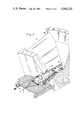
- FIG. 2 is a perspective view of an open air conveyor chute with a cover slide for the large volume silo of FIG. 1 in accordance with the invention.
- a silo area 1 is formed by a cylindrical outer wall 13. Although not shown, material supply means are provided in the upper region of the silo area 1.
- a silo base is defined by a conical dome 2, together with the cylindrical outer wall 13. The silo base is annular and has ramps 11.
- each section is formed by two of the ramps 11, and slopes downwards toward a corresponding open air conveyor chute 7.
- the chutes 7 are always located at the lowest point of each section defined by two ramps 11 and lead to discharge openings 3 in the wall of conical dome 2.
- the open air conveyor chutes 7 terminate at mounting plates 14 for flow regulators 5, which are connected by means of closed air conveyor chutes 6 to a storage tank 9.
- cover slides 8 are moved out of the inner area beneath the conical Dome 2, then they assume the position indicated in FIG. 1 by the continuous lines. In their retracted position 8a, the cover slides 8 are located in the inner area beneath the conical dome as shown by the broken lines in FIG. 1.
- FIG. 2 shows a cover slide 8 shortly before it reaches a position in which the corresponding air conveyor chute 7 is completely covered.
- Slide 8 is guided in rails 15 on ramps 11.
- Hauling cables 16 and 17 are used for operating the slide 8.
- the cover slide 8 On pulling on hauling cable 16 in the direction of the black arrow shown in FIG. 2, the cover slide 8 is advanced in the opposite direction into the silo area 1 as shown by the other black arrow in FIG. 2.
- the slide 8 is moved back into the inner area of conical dome 2 as shown by the other white arrow in FIG. 2.
Landscapes
- Engineering & Computer Science (AREA)
- Mechanical Engineering (AREA)
- Chemical & Material Sciences (AREA)
- Chemical Kinetics & Catalysis (AREA)
- Filling Or Emptying Of Bunkers, Hoppers, And Tanks (AREA)
Abstract
Description
Claims (5)
Priority Applications (1)
| Application Number | Priority Date | Filing Date | Title |
|---|---|---|---|
| US06/563,778 US4566232A (en) | 1983-12-21 | 1983-12-21 | Large volume silo for bulk material, particularly raw cement powder |
Applications Claiming Priority (1)
| Application Number | Priority Date | Filing Date | Title |
|---|---|---|---|
| US06/563,778 US4566232A (en) | 1983-12-21 | 1983-12-21 | Large volume silo for bulk material, particularly raw cement powder |
Publications (1)
| Publication Number | Publication Date |
|---|---|
| US4566232A true US4566232A (en) | 1986-01-28 |
Family
ID=24251873
Family Applications (1)
| Application Number | Title | Priority Date | Filing Date |
|---|---|---|---|
| US06/563,778 Expired - Fee Related US4566232A (en) | 1983-12-21 | 1983-12-21 | Large volume silo for bulk material, particularly raw cement powder |
Country Status (1)
| Country | Link |
|---|---|
| US (1) | US4566232A (en) |
Cited By (5)
| Publication number | Priority date | Publication date | Assignee | Title |
|---|---|---|---|---|
| US4671030A (en) * | 1985-04-03 | 1987-06-09 | Claudius Peters Ag | Bulk silo with aerated mixing or homogenizing chamber |
| US4793529A (en) * | 1986-07-23 | 1988-12-27 | Claudius Peters Ag | Emptying device for a bulk silo |
| US4989380A (en) * | 1988-07-28 | 1991-02-05 | Ibau Hamburg Ingenieurgeselllschaft Industriebau Mbh | Silo for pulverulent and fine-grained bulk materials |
| US20110277404A1 (en) * | 2010-05-13 | 2011-11-17 | Ken Babcock | Grain storage pit |
| WO2020120211A1 (en) | 2018-12-12 | 2020-06-18 | Thyssenkrupp Industrial Solutions Ag | Silo for bulk material |
Citations (11)
| Publication number | Priority date | Publication date | Assignee | Title |
|---|---|---|---|---|
| US1565121A (en) * | 1924-11-26 | 1925-12-08 | Thompson William | Silo or bin for the storage of grain or the like |
| US3170609A (en) * | 1964-02-20 | 1965-02-23 | Entpr Railway Equipment Co | Sliding hopper closure operating and supporting mechanism |
| US3319807A (en) * | 1965-05-28 | 1967-05-16 | Peerless Trailer And Truck Ser | Dumping type storage bin |
| US3365812A (en) * | 1965-01-01 | 1968-01-30 | Borrow Edgar Wilfred | Silos |
| US3888390A (en) * | 1974-06-17 | 1975-06-10 | Toledo Stamping & Mfg | Apparatus for metering particulate material |
| US3889826A (en) * | 1974-01-25 | 1975-06-17 | Mcnally Pittsburg Manufacturin | Reversible car plow feeder for stock pile recovery systems |
| DE2455246A1 (en) * | 1974-11-22 | 1976-05-26 | Bernhard Ruberg | High level silo with outlet unit - with outlet element fitted to central outlet channel making circular movements above silo floor |
| US4125970A (en) * | 1977-06-01 | 1978-11-21 | Vidal Henri C | Bulk storage facility |
| US4161255A (en) * | 1976-12-02 | 1979-07-17 | Ropert Claude P | Device for discharging materials lying upon a storage area |
| US4273267A (en) * | 1978-06-02 | 1981-06-16 | Societe Anonyme Dite: Transitube-Project | Device for extracting and proportioning pulverulent products |
| US4475672A (en) * | 1982-07-06 | 1984-10-09 | Whitehead Jerald M | Hopper discharge device |
-
1983
- 1983-12-21 US US06/563,778 patent/US4566232A/en not_active Expired - Fee Related
Patent Citations (11)
| Publication number | Priority date | Publication date | Assignee | Title |
|---|---|---|---|---|
| US1565121A (en) * | 1924-11-26 | 1925-12-08 | Thompson William | Silo or bin for the storage of grain or the like |
| US3170609A (en) * | 1964-02-20 | 1965-02-23 | Entpr Railway Equipment Co | Sliding hopper closure operating and supporting mechanism |
| US3365812A (en) * | 1965-01-01 | 1968-01-30 | Borrow Edgar Wilfred | Silos |
| US3319807A (en) * | 1965-05-28 | 1967-05-16 | Peerless Trailer And Truck Ser | Dumping type storage bin |
| US3889826A (en) * | 1974-01-25 | 1975-06-17 | Mcnally Pittsburg Manufacturin | Reversible car plow feeder for stock pile recovery systems |
| US3888390A (en) * | 1974-06-17 | 1975-06-10 | Toledo Stamping & Mfg | Apparatus for metering particulate material |
| DE2455246A1 (en) * | 1974-11-22 | 1976-05-26 | Bernhard Ruberg | High level silo with outlet unit - with outlet element fitted to central outlet channel making circular movements above silo floor |
| US4161255A (en) * | 1976-12-02 | 1979-07-17 | Ropert Claude P | Device for discharging materials lying upon a storage area |
| US4125970A (en) * | 1977-06-01 | 1978-11-21 | Vidal Henri C | Bulk storage facility |
| US4273267A (en) * | 1978-06-02 | 1981-06-16 | Societe Anonyme Dite: Transitube-Project | Device for extracting and proportioning pulverulent products |
| US4475672A (en) * | 1982-07-06 | 1984-10-09 | Whitehead Jerald M | Hopper discharge device |
Non-Patent Citations (2)
| Title |
|---|
| Neues Zentralsilosystem und Rohmehldosierung mit Digitalem Regler und Mikorprozessor [New Central Silo System and Rawmeal Flow Control via Digital Controller and Microprocessor]; Von G. Hendriock, New York; Zement-Kalk-Gips-Nr. 8/1983, pp. 450-453. |
| Neues Zentralsilosystem und Rohmehldosierung mit Digitalem Regler und Mikorprozessor New Central Silo System and Rawmeal Flow Control via Digital Controller and Microprocessor ; Von G. Hendriock, New York; Zement Kalk Gips Nr. 8/1983, pp. 450 453. * |
Cited By (6)
| Publication number | Priority date | Publication date | Assignee | Title |
|---|---|---|---|---|
| US4671030A (en) * | 1985-04-03 | 1987-06-09 | Claudius Peters Ag | Bulk silo with aerated mixing or homogenizing chamber |
| US4793529A (en) * | 1986-07-23 | 1988-12-27 | Claudius Peters Ag | Emptying device for a bulk silo |
| US4989380A (en) * | 1988-07-28 | 1991-02-05 | Ibau Hamburg Ingenieurgeselllschaft Industriebau Mbh | Silo for pulverulent and fine-grained bulk materials |
| US20110277404A1 (en) * | 2010-05-13 | 2011-11-17 | Ken Babcock | Grain storage pit |
| US8567135B2 (en) * | 2010-05-13 | 2013-10-29 | Ken Babcock | Grain storage pit |
| WO2020120211A1 (en) | 2018-12-12 | 2020-06-18 | Thyssenkrupp Industrial Solutions Ag | Silo for bulk material |
Similar Documents
| Publication | Publication Date | Title |
|---|---|---|
| US4361254A (en) | Hopper for storing free flowing solid material | |
| US4375335A (en) | Silo combination for mixing stored material | |
| US4566232A (en) | Large volume silo for bulk material, particularly raw cement powder | |
| US3148865A (en) | Pneumatic conveying and conditioning method and apparatus | |
| US4001488A (en) | Apparatus for feeding charge to an electric smelting furnace | |
| US4067452A (en) | Charging apparatus for receptacle | |
| US3302805A (en) | Materials distributor of a blast furnace | |
| US4949940A (en) | Charging arrangement for shaft furnaces, in particular blast furnaces | |
| US3543955A (en) | Blast furnace top | |
| US3476374A (en) | Apparatus for charging a blast furnace continuously | |
| US2965250A (en) | Charging devices for shaft furnaces | |
| US4451925A (en) | Charging system for electric arc furnaces | |
| US3244298A (en) | Automatic reverberatory furnace charging | |
| US1167883A (en) | Method of charging blast-furnaces. | |
| US910233A (en) | Furnace-charging apparatus. | |
| US4238076A (en) | Apparatus for building up and repairing the refractory lining of industrial furnaces and hot-running vessels | |
| EP1387137B1 (en) | Apparatus for charging of a blast furnace via conveyor belt | |
| US3508671A (en) | Blast furnace skip car | |
| JP2782786B2 (en) | Raw material charging apparatus and charging method for bellless blast furnace | |
| US3171637A (en) | Vertical shaft kilns for sintering particulate materials and method of operating | |
| JPH0694567B2 (en) | Raw material charging device | |
| SU58894A1 (en) | Device for loading charge into shaft furnaces | |
| DE3243222A1 (en) | Large-capacity silo for bulk material, especially cement raw meal | |
| SU1049548A1 (en) | Charging apparatus for blast furnace | |
| JPH0128090B2 (en) |
Legal Events
| Date | Code | Title | Description |
|---|---|---|---|
| AS | Assignment |
Owner name: IBAU BARCELONA S.A. TUSET, 19, BARCELONA 6 / SPAIN Free format text: ASSIGNMENT OF ASSIGNORS INTEREST.;ASSIGNOR:KLEIN-ALBENHAUSEN, HEINRICH;REEL/FRAME:004251/0414 Effective date: 19841205 |
|
| FEPP | Fee payment procedure |
Free format text: PAYOR NUMBER ASSIGNED (ORIGINAL EVENT CODE: ASPN); ENTITY STATUS OF PATENT OWNER: SMALL ENTITY |
|
| AS | Assignment |
Owner name: BARCLAYS-AMERICAN/BUSINESS CREDIT, INC., 111 FOUND Free format text: SECURITY INTEREST;ASSIGNOR:FULLER COMPANY;REEL/FRAME:004994/0255 Effective date: 19881214 |
|
| FPAY | Fee payment |
Year of fee payment: 4 |
|
| AS | Assignment |
Owner name: FULLER COMPANY, PENNSYLVANIA Free format text: RELEASED BY SECURED PARTY;ASSIGNOR:BARCLAYS BUSINESS CREDIT, INC., A CORP OF CT;REEL/FRAME:005465/0255 Effective date: 19900912 |
|
| FEPP | Fee payment procedure |
Free format text: PAYER NUMBER DE-ASSIGNED (ORIGINAL EVENT CODE: RMPN); ENTITY STATUS OF PATENT OWNER: SMALL ENTITY Free format text: PAYOR NUMBER ASSIGNED (ORIGINAL EVENT CODE: ASPN); ENTITY STATUS OF PATENT OWNER: SMALL ENTITY |
|
| FPAY | Fee payment |
Year of fee payment: 8 |
|
| REMI | Maintenance fee reminder mailed | ||
| LAPS | Lapse for failure to pay maintenance fees | ||
| FP | Lapsed due to failure to pay maintenance fee |
Effective date: 19980128 |
|
| STCH | Information on status: patent discontinuation |
Free format text: PATENT EXPIRED DUE TO NONPAYMENT OF MAINTENANCE FEES UNDER 37 CFR 1.362 |