US4562719A - Method for drawing heavy wall shells with a multi-step inside edge - Google Patents
Method for drawing heavy wall shells with a multi-step inside edge Download PDFInfo
- Publication number
- US4562719A US4562719A US06/705,357 US70535785A US4562719A US 4562719 A US4562719 A US 4562719A US 70535785 A US70535785 A US 70535785A US 4562719 A US4562719 A US 4562719A
- Authority
- US
- United States
- Prior art keywords
- draw
- punch
- forming
- shoulder
- finishing
- Prior art date
- Legal status (The legal status is an assumption and is not a legal conclusion. Google has not performed a legal analysis and makes no representation as to the accuracy of the status listed.)
- Expired - Fee Related
Links
- 238000000034 method Methods 0.000 title claims description 19
- 239000000463 material Substances 0.000 claims description 42
- 230000013011 mating Effects 0.000 claims 1
- 229910052751 metal Inorganic materials 0.000 description 20
- 239000002184 metal Substances 0.000 description 20
- 230000008569 process Effects 0.000 description 8
- 230000007423 decrease Effects 0.000 description 6
- 230000015572 biosynthetic process Effects 0.000 description 5
- 238000003754 machining Methods 0.000 description 4
- 150000002739 metals Chemical class 0.000 description 3
- IJGRMHOSHXDMSA-UHFFFAOYSA-N Atomic nitrogen Chemical compound N#N IJGRMHOSHXDMSA-UHFFFAOYSA-N 0.000 description 2
- 230000001419 dependent effect Effects 0.000 description 2
- 238000013461 design Methods 0.000 description 2
- 230000000153 supplemental effect Effects 0.000 description 2
- 229910000851 Alloy steel Inorganic materials 0.000 description 1
- 229910001369 Brass Inorganic materials 0.000 description 1
- 229910000975 Carbon steel Inorganic materials 0.000 description 1
- 229910052782 aluminium Inorganic materials 0.000 description 1
- XAGFODPZIPBFFR-UHFFFAOYSA-N aluminium Chemical compound [Al] XAGFODPZIPBFFR-UHFFFAOYSA-N 0.000 description 1
- 239000010951 brass Substances 0.000 description 1
- 239000010962 carbon steel Substances 0.000 description 1
- 230000002950 deficient Effects 0.000 description 1
- 238000011161 development Methods 0.000 description 1
- 230000001788 irregular Effects 0.000 description 1
- 238000012986 modification Methods 0.000 description 1
- 230000004048 modification Effects 0.000 description 1
- 229910052757 nitrogen Inorganic materials 0.000 description 1
- 230000000704 physical effect Effects 0.000 description 1
- 230000008707 rearrangement Effects 0.000 description 1
- 230000009467 reduction Effects 0.000 description 1
- 238000007493 shaping process Methods 0.000 description 1
- 238000006467 substitution reaction Methods 0.000 description 1
- 238000012546 transfer Methods 0.000 description 1
Images


Classifications
-
- B—PERFORMING OPERATIONS; TRANSPORTING
- B21—MECHANICAL METAL-WORKING WITHOUT ESSENTIALLY REMOVING MATERIAL; PUNCHING METAL
- B21D—WORKING OR PROCESSING OF SHEET METAL OR METAL TUBES, RODS OR PROFILES WITHOUT ESSENTIALLY REMOVING MATERIAL; PUNCHING METAL
- B21D22/00—Shaping without cutting, by stamping, spinning, or deep-drawing
- B21D22/20—Deep-drawing
- B21D22/21—Deep-drawing without fixing the border of the blank
-
- B—PERFORMING OPERATIONS; TRANSPORTING
- B21—MECHANICAL METAL-WORKING WITHOUT ESSENTIALLY REMOVING MATERIAL; PUNCHING METAL
- B21D—WORKING OR PROCESSING OF SHEET METAL OR METAL TUBES, RODS OR PROFILES WITHOUT ESSENTIALLY REMOVING MATERIAL; PUNCHING METAL
- B21D51/00—Making hollow objects
- B21D51/16—Making hollow objects characterised by the use of the objects
- B21D51/54—Making hollow objects characterised by the use of the objects cartridge cases, e.g. for ammunition, for letter carriers in pneumatic-tube plants
Definitions
- the present invention relates to the forming of metal, and in particular to the forming of metal by drawing.
- metals into a variety of shapes are well-known metal forming process. These shapes include cylindrical cups and tubes with curved side walls as well as shapes with angular side walls, with square or rectangular cross sections, for example. Countless numbers of items are produced by this process, with one example being a grenade body. Typical metals used in the process are carbon steel, alloy steel, aluminum, and brass, as well as other types of metals.
- a common shape desired to be formed by drawing is essentially a cylindrical cup formed with one end closed.
- the cup may be drawn in a single or multistage process.
- Each stage includes a punch which drives the metal to be formed into a die to form an intermediate or final shape.
- the metal is processed through a number of draw stations and completed in a series of finishing stations. The number of draw stations required depends upon the inside diameter of the cylinder, the height of the cylinder, metal thickness and physical properties of the metal.
- an apparatus for forming a material into a cup part having side walls and a bottom portion.
- the apparatus includes a first step forming stage of forming for forming a step in the walls of the parts.
- the first step forming stage includes a die and cooperating punch to draw the material through the die to form the cup part.
- the punch has a nose portion for contacting the bottom portion of the cup part and an enlarged portion or portions for forming an annular surface or surfaces on the side walls perpendicular to the axis of the drawn cup part.
- a second and subsequent step forming stage includes a die and cooperating punch to draw the material through the die to form the cup part.
- the punch for the second step forming stage has a nose portion for contacting the bottom portion of the cup part and an enlarged midportion for forming a first annular surface on the side walls perpendicular to the axis of the cup part to form at least a secondary step.
- a neck portion on the punch of the second step forming stage has a larger diameter than the midportion thereof to form a draw shoulder on the punch to mate with the primary step formed in the initial step forming stage.
- At least one finishing stage of forming is provided to form the bottom portion of the cup part.
- the finishing stage includes a finishing die and cooperating punch to form the material through the finishing die.
- the punch includes structure for contacting the primary and secondary steps in the side walls of the drawn cup part to control the stresses in the side walls thereof.
- a method for forming a material into a cup part having side walls and a bottom portion includes the step of forming the material in at least two stages.
- the first stage includes a die and cooperating punch to draw the material to the die to form the cup part.
- the punch in the first stage has a nose portion for contacting the bottom portion of the cup part and an enlarged portion for forming an annular surface on the side walls perpendicular to the axis of the drawn cup part to form a primary step.
- the second stage of forming comprises forming a second step in the part closer to the bottom of the part with a punch that has a nose portion for contacting the bottom portion of the cup part, and an enlarged midportion for forming the additional step in the side walls of the drawn cup part and an enlarged neck portion for forming a draw shoulder on the punch to mate with the primary step from the first step forming stage.
- FIG. 1 is a partial side cross-sectional view of a forming machine incorporating the teachings of the present invention
- FIGS. 2a-h are sequential detail illustrations of the forming of a cup part in one stage of the forming machine
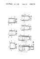
- FIGS. 3a-e are cross-sectional side views of the cup part formed in each of the draw stages of the forming machine and the final form station;
- FIGS. 4a-g are cross-sectional side views of another embodiment of the cup part forming apparatus wherein multi-step side walls are formed.
- FIG. 1 illustrates a forming machine 10 for forming a finished cup part 12 from a circular plate-like blank material 14.
- Cup part 12 may have any desired cross section, while the material 14 can comprise any formable metal or other formable material.
- the forming machine 10 performs three major formation functions which can include one or more individual forming stations.
- the first function is the drawing of the material 14 at the first draw station 18, second draw station 20, third draw station 22 and fourth draw station 24.
- Each draw station progressively decreases the diameter of the intermediate cup part shape and increases the length of the side walls 26.
- the thickness of both side walls 26 and bottom portion 28 remain substantially the same.
- the number of draw stations varies with part size and material and four draw stations are shown merely as an example.
- the bottom portion 28 of the finished cup part 12 is formed in the final two formation functions.
- the second formation function is performed by first necking stage 30 and second necking stage 32 which act primarily to form the bottom portion 28.
- the number of necking stages is dependent upon the complexity of the bottom portion configuration.
- the third formation function is performed by a final form station 34 which forms the final shape of bottom portion 28.
- the forming machine 10 includes a lower die shoe 36 which is typically stationary. An upper die shoe 38 is supported for vertical motion above the lower die shoe 36.
- Each of the stations include a punch, a die and an ejector pin 39.
- the punches for the stations are located by punch holders 40 secured to the upper die shoe 38.
- Each of the dies are located on the lower die shoe 36. Die and punch loads are supported by the lower die shoe 36 and upper die shoe 38, respectively.
- the ejector pins 39 at each stage are movable relative to the associated dies to remove a formed intermediate or final cup part from the die.
- the ejector pins 39 lift the formed final or intermediate cup parts free of the dies as seen in FIG. 2h.
- the pins 39 can also function to support bottom portion 28, or so called "coining" loads.
- the coining load is supported by lower die shoe 36.
- the pins 39 could be operated by mechanical cam operation, air cylinders or nitrogen or hydraulic cushions at each station, or a cross bar actuated by two cushions in the bed of the machine 10.
- a stripper 42 is provided with apertures to permit passage of the punches therethrough for stripping the formed intermediate or final cup part from the punch. Stripper 42 can be substituted for by lever type strippers at each station, cross bar knockouts provided in the slide of the machine 10 or another suitable type.
- An individual finished cup part 12 is formed from material 14 by moving the piece sequentially through each stage from right to left as seen in FIG. 1. Apparatus for performing this transfer is well-known in the art and will not be described.
- the punch 44 employed in the first draw station 18 is formed with a relatively reduced diameter nose portion 45 and a relatively enlarged diameter portion 46 as best seen in FIG. 2a.
- the draw die 48 has an upper die surface 50 having a wide flare and a relatively straight lower die surface 52 separated by the minor diameter 54.
- the dimensions of surface 52 and diameter 54 can vary, and in some die designs can be identically sized.
- the pressure applied by the decending punch 44 initially deforms the material 14 as shown in FIG. 2b to fit into the contour of the upper die surface 50 of the draw die 48. As the punch 44 continues to decend, it pulls the material through the minor diameter 54 of the draw die 48 to form essentially a straight wall intermediate cup shape as illustrated in the sequence of FIGS. 2c-h.
- the punch 44 is pressing against a small cross section of the bottom portion 28 of the material being drawn through the draw die 48. This imposes a tensile stress in the side walls 26 of the immediate cup part.
- the contour of the die surfaces 50 and 52 are carefully developed to suit the metal thickness and particular metal to be formed and is an important consideration in the design of the die.
- the interface between the nose portion 45 and enlarged diameter portion 46 forms an annular surface 56 on the punch 44 perpendicular the motion of the punch.
- the annular surface 56 can be sharply defined, as seen in the upper detail view in FIG. 2a or have a more gradual definition as seen in the lower detail view of FIG. 2a.
- the annular surface 56 can be formed by fitting a sleeve over a punch with the same outer diameter as nose portion 45.
- the length of the nose portion 45 is designed so that the enlarged diameter portion 46 passes the minor diameter 54 of the draw die 48 before the open end 58 of the intermediate cup part passes through the minor diameter 54.
- the clearance between the outside diameter of the enlarged diameter portion 46 and the minor diameter 54 is less than the metal thickness of the intermediate cup part. Therefore, the final relatively small amount of material that passes through the draw die is reduced in wall thickness to create an annular surface or step 60 at the open end as best seen in FIG. 3a.
- the step 60 can be formed at any position along side walls 26 desired and need not be near the open end.
- the specification of a part may require an annular step to be formed on the side wall in the final shape. In the past, a separate machining step would be required to form this step.
- the annular surface 56 can be positioned to form the step at the specified position. The distance from the material contacting surface of the nose portion 45 and the step 60 is precisely controlled.
- the step is formed perpendicular and concentric to the axis of the drawn intermediate cup part and motion of direction of punch 44.
- the volume of material within the intermediate cup part below the step 60 is therefore established precisely which is critical for controlling part definition in subsequent operations.
- the step 60 can be formed concentric and at an angle to the axis of the drawn intermediate cup part. This results in an annular shoulder tapering inwardly toward the bottom portion 28.
- the surface of this annular shoulder can also have a radius formed therein with the radial center thereof external or internal to the formed part.
- the second draw stage 20 includes a punch 62 and draw die 64.
- the third draw station 22 includes a punch 66 and a draw die 68.
- the fourth draw station 24 includes a punch 70 and draw die 72.
- Each of the punches 62, 66 and 70 also include a nose portion and enlarged diameter portion.
- the punches and draw dies are designed to progressively decrease the cup diameter and increase the cup length of the intermediate cup part as illustrated in FIGS. 3a-d.
- the difference in diameter of the nose portion and enlarged diameter portion at each station progressively increases to increase the amount of step 60 in the drawn cup part, again as best seen in FIGS. 3a-d.
- the step 60 in the intermediate cup part has been fully developed. It will be observed that the irregularity of the open end 58 of the intermediate cup parts becomes more severe upon each draw. However, the step 60 formed in the draw processes retains its concentricity and shape with respect to the angle thereof formed with the axis of the drawn part.
- the step formed in the side walls depends not only on this difference, but on the force transmitted through the punch to the side walls.
- punches 44 and 62 can have the same diameter difference and punches 66 and 70 have the same, albeit layer, diameter difference.
- the force exerted on the formed part by punches 44, 62, 66 and 70 can then be varied to achieve the development of the step in four stages as done by the punches illustrated in FIGS. 2c-h.
- the step 60 at the open end of the intermediate cup part can be used in the subsequent forming of the bottom portion 28 at the first necking station 30, second necking station 32 and final forming station 34 to result in the final form shown in FIG.
- the first necking station 30 includes a punch 71 and die 73.
- the second necking station 32 includes a punch 74 and die 76.
- the final forming station 34 includes a punch 78 and die 80.
- necking refers to the configuration imparted to the bottom portion 28. The number of necking operations are therefore dependent upon the complexity of the configuration desired in the bottom portion 28.
- uniform forming pressure can be applied to the side walls adjacent to the open end 58 of the intermediate cup part simultaneously with application of pressure through the nose portion of the punches 71, 74 and 78 at each of the stations 30, 32 and 34. Forming pressure can be applied solely through the side walls if desired.
- the punches 71, 74 and 78 at each of the stations are made with a relatively reduced diameter nose portion and a relatively enlarged diameter portion.
- the interface or shoulder 61 on the punches 71, 74 and 78 can be positioned to contact the step 60 to provide the desired ratio of force applied through the step 60 and to the bottom portion 28.
- step 60 established by the draw stations 18-24 and the perpendicularity of step 60 to the axis of the cup part enables application of uniform compressive forces throughout the circumference of the part and consistently for every part formed.
- step 60 dimensioned perpendicular to the axis of the drawn part to apply uniform compressive forces throughout the circumference of the part.
- the compressive forces applied to the cup part through the step 60 assists greatly to move the material and cause the material to fill the envelope defined by the punch on the inside and the die on the outside thereof. It is also possible to control the amount of compressive forces applied through the cylindrical portion. For example, for some parts it may be desirable to apply all of the forming pressure through the side walls 26 at step 60 and none through the nose portion of the punch to the bottom portion 28.
- shapes having curved side walls with a non-circular cross section can be formed.
- shapes having angular side walls can be formed, including shapes with square and rectangular cross sections, and polygon cross sections such as hexagons and octagons.
- Shapes can also be formed with apertures or holes in the bottom portion. These apertures can be smaller than the inner dimensions of the side walls and have any desired configuration. The apertures can be as large as the inner dimensions of the side walls to form a tubular or duct. Force can be applied through the step in the side walls of the tubular or duct part to form a desired geometric shape to one end of the port.
- the step formed in the side walls would not be annular. However, the step would always define a surface that maintains the initial angular relationship to the direction of motion of the punch and would closely approximate the cross section of the side walls.
- the punches and dies would naturally be made to produce the desired part shape and step configuration.
- FIGS. 4a-g there is illustrated a series of forming steps for an alternate embodiment of the present invention.
- FIGS. 4a-c represent first, second and third drawing stages which are identical to the stages depicted in FIGS. 3a-c. These drawing stages are effected utilizing the dies 48, 64 and 68 with the corresponding punches, 44, 62 and 66 respectively. Each of the successive drawing stages represented in FIGS. 4a-c effectively increases the length of the sidewalls 26 and the diameter thereof.
- FIG. 4d there is illustrated the fourth draw stage of the operation illustrating a punch 70' disposed within the material 14.
- the punch 70' is comprised of an upper portion 90, a middle portion 92 having a smaller diameter than the upper portion 90 and a nose portion 94 having a yet smaller diameter.
- the decrease of diameter between the upper portion 90 and the middle portion 92 forms a shoulder 96 that is operable to mate with the step 60.
- the interface between the middle portion 92 and the nose portion 92 forms a shoulder 98 that, as illustrated, is beveled with a downward and inwardly tapering wall from the lower edge of the middle portion 92 to the top of the nose portion.
- the shoulder 98 may be perpendicular and concentric to the axis of the part and the motion of the punch 70'.
- the shoulder 98 can have a radial cross section with the radial center thereof external to the punch 70'.
- the step 100 that has been formed is in addition to the step 60.
- the thickness of the wall 26 is defined by the diameter of the various portions of the punch 70' in relation to the minor opening through the die 72.
- the nose portion 94 passes through the die 72, the overall length of the wall 26 increases depending upon the decrease in diameter from that illustrated in FIG. 4c.
- the shoulder 98 passes through the die 72, the thickness of the wall 26 decreases to form the step 100.
- the dimension between the shoulders 96 and 98 is designed such that when the shoulder 96 passes through the die 72, it mates with the step 60. As described above, the angular relationship of the step 60 with respect to the axis of the part and the direction of motion of the punch 70' is maintained. In a similar manner, the angular relationship of the step 100 with respect to the axis of the part is also maintained.
- FIGS. 4e-4g illustrate three necking stages to form a desired shape for the lower portion of the cup 12.
- a punch 71' is utilized in the stage represented in FIG. 4e to perform the necking function. This function is identical with the neck formed in FIG. 3e.
- the punch 71' has an additional edge 99 as compared to the punch 71 utilized with the first stage of the necking to form the cup part in FIG. 3e.
- This shoulder 99 is operable in conjunction with the shoulder 61 to apply uniform forming pressure to the sidewalls adjacent to the open end 58 of the intermediate cup part simultaneously with application of pressure to the nose portion of the punch 71'. Forming pressure can be applied solely through the sidewalls as desired.
- both of the shoulders 61 and 99 can be positioned to contact the steps 60 and 100, respectively, to provide the desired ratio of force applied through the respective steps to the bottom portion 28.
- the longitudinal forces directed along the longitudinal axis of the punch 71' can be dispersed along the length of the wall 26.
- FIGS. 4f and 4g illustrate additional necking stages that are equivalent to the stations 32 and 34 with the exception that they utilize punches having a shoulder to mate with the step 100.
- the shoulders are not shown for simplicity purposes.
- the height in the inside diameter of the step 100 may be altered within certain limits to suit dimensional requirements of a desired part.
- additional steps simultaneously with the second step by utilizing another punch in the fourth drawing stage.
- the second and/or additional steps are required and would otherwise be produced by the additional step of machining.
- Imparting the steps in the metal forming operation further reduces the diameter of the blank with an associated reduction of the amount of material used.
- a groove or threads can be formed along the inside of the walls 26 with machining at a later time. With the additional steps, the amount of metal that must be removed by machining is substantially reduced in the metal forming operation.
- the present invention greatly enhances the ability to precisely form complex closed ends and uniform wall thickness by applying forming pressure through both the nose portion of a punch and through compressive forces applied in the cylindrical portion through the step formed therein.
Landscapes
- Engineering & Computer Science (AREA)
- Mechanical Engineering (AREA)
- Shaping Metal By Deep-Drawing, Or The Like (AREA)
Abstract
Description
Claims (7)
Priority Applications (1)
| Application Number | Priority Date | Filing Date | Title |
|---|---|---|---|
| US06/705,357 US4562719A (en) | 1983-09-23 | 1985-02-25 | Method for drawing heavy wall shells with a multi-step inside edge |
Applications Claiming Priority (2)
| Application Number | Priority Date | Filing Date | Title |
|---|---|---|---|
| US06/535,064 US4527413A (en) | 1982-08-13 | 1983-09-23 | Apparatus for drawing heavy wall shells with a multi-step inside edge |
| US06/705,357 US4562719A (en) | 1983-09-23 | 1985-02-25 | Method for drawing heavy wall shells with a multi-step inside edge |
Related Parent Applications (1)
| Application Number | Title | Priority Date | Filing Date |
|---|---|---|---|
| US06/535,064 Division US4527413A (en) | 1982-08-13 | 1983-09-23 | Apparatus for drawing heavy wall shells with a multi-step inside edge |
Publications (1)
| Publication Number | Publication Date |
|---|---|
| US4562719A true US4562719A (en) | 1986-01-07 |
Family
ID=27064698
Family Applications (1)
| Application Number | Title | Priority Date | Filing Date |
|---|---|---|---|
| US06/705,357 Expired - Fee Related US4562719A (en) | 1983-09-23 | 1985-02-25 | Method for drawing heavy wall shells with a multi-step inside edge |
Country Status (1)
| Country | Link |
|---|---|
| US (1) | US4562719A (en) |
Cited By (13)
| Publication number | Priority date | Publication date | Assignee | Title |
|---|---|---|---|---|
| US4785648A (en) * | 1987-03-23 | 1988-11-22 | Allied Products Corporation | Method and apparatus for embossing the inside surface of a cup-shaped article |
| US5632181A (en) * | 1995-02-23 | 1997-05-27 | Verson, A Division Of Allied Products Corporation | System and method for transferring a work piece in a multi-station press |
| US5875673A (en) * | 1997-12-30 | 1999-03-02 | Verson, A Division Of Allied Products Corporation | Orientation station for multi-station metal-forming machines |
| US6430984B2 (en) * | 1998-09-16 | 2002-08-13 | Alcan Technology & Management Ltd. | Process for manufacturing shaped packaging |
| US20090049691A1 (en) * | 2006-05-12 | 2009-02-26 | Chih-Hung Cheng | Method for embedding heat pipe into heat-conducting seat |
| US20120264580A1 (en) * | 2011-04-15 | 2012-10-18 | Uhlmann Pac-Systeme Gmbh & Co. Kg | Forming device for the cold-forming of pockets for medical or pharmaceutical products in a sheet |
| CN104307992A (en) * | 2014-10-20 | 2015-01-28 | 湖南省耒耕轻型耕田机制造有限公司 | Center frame molding lower die assembly |
| US20150093591A1 (en) * | 2012-04-02 | 2015-04-02 | Adval Tech Holding Ag | Method for producing pot-shaped components in a shaping process |
| US20170128998A1 (en) * | 2014-06-13 | 2017-05-11 | Nisshin Steel Co., Ltd. | Formed material manufacturing method and formed material |
| WO2017186234A1 (en) | 2016-04-28 | 2017-11-02 | Fritz Werner Industrie-Ausrüstungen Gmbh | Transfer press having a c-shaped ram |
| US20180138667A1 (en) * | 2016-11-11 | 2018-05-17 | Ngk Spark Plug Co., Ltd. | Processing apparatus, method for manufacturing molded product, and method for manufacturing spark plug electrode |
| CN110681754A (en) * | 2019-10-10 | 2020-01-14 | 秦皇岛通桥科技有限公司 | Integrated forming method of large-volume oil pan with lugs |
| US11253899B2 (en) * | 2018-03-01 | 2022-02-22 | Alireza Mardani | Production of reinforced double-layer parts |
Citations (6)
| Publication number | Priority date | Publication date | Assignee | Title |
|---|---|---|---|---|
| FR1253845A (en) * | 1959-11-17 | 1961-02-17 | Svenska Metallverken Ab | Process for shaping a strip to obtain a hollow body, in particular for a body of projectiles, and device for implementing this process |
| DE1932139A1 (en) * | 1969-06-25 | 1971-01-21 | Dynamit Nobel Ag | Deep drawing steel cartridge cases |
| US3893321A (en) * | 1973-12-04 | 1975-07-08 | Gfm Fertigungstechnik | Swaging machine |
| US3998087A (en) * | 1975-10-30 | 1976-12-21 | Gulf & Western Manufacturing Company | Press slide with extendable and retractable tool support |
| US4147049A (en) * | 1977-06-16 | 1979-04-03 | Textron, Inc. | Drawing heavy walled parts |
| GB1602539A (en) * | 1978-05-31 | 1981-11-11 | Carnaud Sa | Process for the production of metal cans |
-
1985
- 1985-02-25 US US06/705,357 patent/US4562719A/en not_active Expired - Fee Related
Patent Citations (6)
| Publication number | Priority date | Publication date | Assignee | Title |
|---|---|---|---|---|
| FR1253845A (en) * | 1959-11-17 | 1961-02-17 | Svenska Metallverken Ab | Process for shaping a strip to obtain a hollow body, in particular for a body of projectiles, and device for implementing this process |
| DE1932139A1 (en) * | 1969-06-25 | 1971-01-21 | Dynamit Nobel Ag | Deep drawing steel cartridge cases |
| US3893321A (en) * | 1973-12-04 | 1975-07-08 | Gfm Fertigungstechnik | Swaging machine |
| US3998087A (en) * | 1975-10-30 | 1976-12-21 | Gulf & Western Manufacturing Company | Press slide with extendable and retractable tool support |
| US4147049A (en) * | 1977-06-16 | 1979-04-03 | Textron, Inc. | Drawing heavy walled parts |
| GB1602539A (en) * | 1978-05-31 | 1981-11-11 | Carnaud Sa | Process for the production of metal cans |
Cited By (25)
| Publication number | Priority date | Publication date | Assignee | Title |
|---|---|---|---|---|
| US4785648A (en) * | 1987-03-23 | 1988-11-22 | Allied Products Corporation | Method and apparatus for embossing the inside surface of a cup-shaped article |
| AU617565B2 (en) * | 1987-03-23 | 1991-11-28 | Allied Products Corporation | Method and apparatus for embossing the inside surface of a cup-shaped article |
| AU617566B2 (en) * | 1987-03-23 | 1991-11-28 | Allied Products Corporation | Method and apparatus for embossing the inside surface of a cup-shaped article |
| US5632181A (en) * | 1995-02-23 | 1997-05-27 | Verson, A Division Of Allied Products Corporation | System and method for transferring a work piece in a multi-station press |
| US5722283A (en) * | 1995-02-23 | 1998-03-03 | Verson, A Divison Of Allied Products Corporation | System and method for rotation of cross bars in a multiple station transfer press |
| US5782129A (en) * | 1995-02-23 | 1998-07-21 | Verson, A Division Of Allied Products Corporation | Method for transferring a work piece in a multi-station press |
| US5875673A (en) * | 1997-12-30 | 1999-03-02 | Verson, A Division Of Allied Products Corporation | Orientation station for multi-station metal-forming machines |
| US6430984B2 (en) * | 1998-09-16 | 2002-08-13 | Alcan Technology & Management Ltd. | Process for manufacturing shaped packaging |
| US20090049691A1 (en) * | 2006-05-12 | 2009-02-26 | Chih-Hung Cheng | Method for embedding heat pipe into heat-conducting seat |
| US8387250B2 (en) * | 2006-05-12 | 2013-03-05 | Cpumate Inc. | Method for embedding heat pipe into heat-conducting seat |
| US20120264580A1 (en) * | 2011-04-15 | 2012-10-18 | Uhlmann Pac-Systeme Gmbh & Co. Kg | Forming device for the cold-forming of pockets for medical or pharmaceutical products in a sheet |
| US20150093591A1 (en) * | 2012-04-02 | 2015-04-02 | Adval Tech Holding Ag | Method for producing pot-shaped components in a shaping process |
| US9919351B2 (en) * | 2012-04-02 | 2018-03-20 | Adval Tech Holding Ag | Method for producing pot-shaped components in a shaping process |
| US20170128998A1 (en) * | 2014-06-13 | 2017-05-11 | Nisshin Steel Co., Ltd. | Formed material manufacturing method and formed material |
| US11117178B2 (en) * | 2014-06-13 | 2021-09-14 | Nisshin Steel Co., Ltd. | Formed material manufacturing method and formed material |
| CN104307992A (en) * | 2014-10-20 | 2015-01-28 | 湖南省耒耕轻型耕田机制造有限公司 | Center frame molding lower die assembly |
| US20190118242A1 (en) * | 2016-04-28 | 2019-04-25 | Fritz Werner Industrie-Ausrüstungen Gmbh | Transfer press having a c-shaped ram |
| KR20190002524A (en) * | 2016-04-28 | 2019-01-08 | 프리츠 베르너 인더스트리에-아우스뤼스툰겐 게엠바하 | Transfer presses containing C-shaped ram |
| WO2017186234A1 (en) | 2016-04-28 | 2017-11-02 | Fritz Werner Industrie-Ausrüstungen Gmbh | Transfer press having a c-shaped ram |
| US11712734B2 (en) * | 2016-04-28 | 2023-08-01 | Fritz Werner Industrie-Ausrüstungen Gmbh | Transfer press having a c-shaped ram |
| US20180138667A1 (en) * | 2016-11-11 | 2018-05-17 | Ngk Spark Plug Co., Ltd. | Processing apparatus, method for manufacturing molded product, and method for manufacturing spark plug electrode |
| US10847952B2 (en) * | 2016-11-11 | 2020-11-24 | Ngk Spark Plug Co., Ltd. | Processing apparatus, method for manufacturing molded product, and method for manufacturing spark plug electrode |
| US11253899B2 (en) * | 2018-03-01 | 2022-02-22 | Alireza Mardani | Production of reinforced double-layer parts |
| CN110681754A (en) * | 2019-10-10 | 2020-01-14 | 秦皇岛通桥科技有限公司 | Integrated forming method of large-volume oil pan with lugs |
| CN110681754B (en) * | 2019-10-10 | 2021-09-10 | 秦皇岛通桥科技有限公司 | Integrated forming method of large-volume oil pan with lugs |
Similar Documents
| Publication | Publication Date | Title |
|---|---|---|
| US4562719A (en) | Method for drawing heavy wall shells with a multi-step inside edge | |
| US4527413A (en) | Apparatus for drawing heavy wall shells with a multi-step inside edge | |
| US4509356A (en) | Method and apparatus for drawing heavy wall shells | |
| FI112331B (en) | Method and apparatus for forming a relief member in a sheet metal material and a product made by the method | |
| CN1202844A (en) | Systems and methods for manufacturing decorative shaped metal cans | |
| EP0059432A2 (en) | Press machine | |
| JPS60193834A (en) | Method and device for reinforcing and molding end section ofcan | |
| US4442692A (en) | Tandem ironing land assembly | |
| US3399560A (en) | Method of cold forming a solid ring | |
| JPH08257660A (en) | Production of molded metallic can | |
| US20090116932A1 (en) | Process for Producing Molded Article with Undercut, Forging Apparatus Therefor, and Intermediate Molded Object | |
| AU608695B2 (en) | A method for manufacturing a rotor frame of an electromagnetic clutch | |
| US2751676A (en) | Method of cold working metal | |
| US4559802A (en) | Method for drawing heavy wall shells | |
| US4697445A (en) | Poly-V pulley formed of sheet metal and method and apparatus for making same | |
| EP0955111A1 (en) | Integral structure of sheet material and cylindrical member and production method thereof | |
| US3682122A (en) | Method and apparatus for forming heat exchange fin collars | |
| US4342213A (en) | Closed chamber extrusion method and apparatus for shaping of metal rod into tulip-shaped part | |
| JPH0353049B2 (en) | ||
| JPH04266429A (en) | Manufacturing method of double cylinder | |
| US5918499A (en) | Rivet formation | |
| US5174147A (en) | Method and apparatus for cold extruding universal seal crosspieces | |
| SU671901A1 (en) | Method of manufacturing laminated hollow articles | |
| RU2311983C1 (en) | Annular blanks forming method | |
| JP2001137999A (en) | Manufacturing method of ball part in ball joint |
Legal Events
| Date | Code | Title | Description |
|---|---|---|---|
| FEPP | Fee payment procedure |
Free format text: PAYOR NUMBER ASSIGNED (ORIGINAL EVENT CODE: ASPN); ENTITY STATUS OF PATENT OWNER: LARGE ENTITY |
|
| FPAY | Fee payment |
Year of fee payment: 4 |
|
| AS | Assignment |
Owner name: CONTINENTAL BANK N.A. AS AGENT Free format text: SECURITY INTEREST;ASSIGNOR:ALLIED PRODUCTS CORPORATION, A DE CORP.;REEL/FRAME:005270/0416 Effective date: 19891215 |
|
| AS | Assignment |
Owner name: ALLIED PRODUCTS CORPORATION, ILLINOIS Free format text: ASSIGNMENT OF ASSIGNORS INTEREST.;ASSIGNOR:VERSON ALLSTEEL PRESS COMPANY;REEL/FRAME:005238/0445 Effective date: 19900125 |
|
| AS | Assignment |
Owner name: CONTINENTAL BANK N.A., ILLINOIS Free format text: SECURITY INTEREST;ASSIGNOR:ALLIED PRODUCTS CORPORATION;REEL/FRAME:005748/0940 Effective date: 19900124 Owner name: ALLIED PRODUCTS CORPORATION, A CORP. OF DELAWARE Free format text: RELEASED BY SECURED PARTY;ASSIGNOR:CONTINENTAL BANK N.A.;REEL/FRAME:005635/0117 Effective date: 19900124 |
|
| AS | Assignment |
Owner name: ALLIED PRODUCTS CORPORATION, ILLINOIS Free format text: RELEASED BY SECURED PARTY;ASSIGNOR:CONTINENTAL BANK, N.A.;REEL/FRAME:006419/0461 Effective date: 19930129 |
|
| AS | Assignment |
Owner name: VERSON CORPORATION, ILLINOIS Free format text: ASSIGNMENT OF ASSIGNORS INTEREST.;ASSIGNOR:ALLIED PRODUCTS CORPORATION;REEL/FRAME:006412/0105 Effective date: 19930128 |
|
| AS | Assignment |
Owner name: CONTINENTAL BANK N.A., ILLINOIS Free format text: SECURITY INTEREST;ASSIGNOR:VERSON CORPORATION, A DELAWARE CORP.;REEL/FRAME:006431/0393 Effective date: 19930129 |
|
| FPAY | Fee payment |
Year of fee payment: 8 |
|
| AS | Assignment |
Owner name: VERSON CORPORATION, ILLINOIS Free format text: RELEASE BY SECURED PARTY;ASSIGNOR:CONTINENTAL BANK N.A.;REEL/FRAME:007090/0902 Effective date: 19940621 |
|
| REMI | Maintenance fee reminder mailed | ||
| LAPS | Lapse for failure to pay maintenance fees | ||
| FP | Lapsed due to failure to pay maintenance fee |
Effective date: 19980107 |
|
| STCH | Information on status: patent discontinuation |
Free format text: PATENT EXPIRED DUE TO NONPAYMENT OF MAINTENANCE FEES UNDER 37 CFR 1.362 |