US4557122A - Combined combination and key-type lock - Google Patents
Combined combination and key-type lock Download PDFInfo
- Publication number
- US4557122A US4557122A US06/526,286 US52628683A US4557122A US 4557122 A US4557122 A US 4557122A US 52628683 A US52628683 A US 52628683A US 4557122 A US4557122 A US 4557122A
- Authority
- US
- United States
- Prior art keywords
- lock
- key
- casing
- locking plate
- fixing plate
- Prior art date
- Legal status (The legal status is an assumption and is not a legal conclusion. Google has not performed a legal analysis and makes no representation as to the accuracy of the status listed.)
- Expired - Fee Related
Links
- 210000002105 tongue Anatomy 0.000 claims description 5
- 150000001875 compounds Chemical class 0.000 abstract description 7
- 238000000034 method Methods 0.000 description 2
- 230000003247 decreasing effect Effects 0.000 description 1
- 230000001771 impaired effect Effects 0.000 description 1
Images


Classifications
-
- E—FIXED CONSTRUCTIONS
- E05—LOCKS; KEYS; WINDOW OR DOOR FITTINGS; SAFES
- E05B—LOCKS; ACCESSORIES THEREFOR; HANDCUFFS
- E05B37/00—Permutation or combination locks; Puzzle locks
- E05B37/12—Permutation or combination locks; Puzzle locks with tumbler discs on several axes
-
- Y—GENERAL TAGGING OF NEW TECHNOLOGICAL DEVELOPMENTS; GENERAL TAGGING OF CROSS-SECTIONAL TECHNOLOGIES SPANNING OVER SEVERAL SECTIONS OF THE IPC; TECHNICAL SUBJECTS COVERED BY FORMER USPC CROSS-REFERENCE ART COLLECTIONS [XRACs] AND DIGESTS
- Y10—TECHNICAL SUBJECTS COVERED BY FORMER USPC
- Y10T—TECHNICAL SUBJECTS COVERED BY FORMER US CLASSIFICATION
- Y10T70/00—Locks
- Y10T70/70—Operating mechanism
- Y10T70/7141—Combination and key
-
- Y—GENERAL TAGGING OF NEW TECHNOLOGICAL DEVELOPMENTS; GENERAL TAGGING OF CROSS-SECTIONAL TECHNOLOGIES SPANNING OVER SEVERAL SECTIONS OF THE IPC; TECHNICAL SUBJECTS COVERED BY FORMER USPC CROSS-REFERENCE ART COLLECTIONS [XRACs] AND DIGESTS
- Y10—TECHNICAL SUBJECTS COVERED BY FORMER USPC
- Y10T—TECHNICAL SUBJECTS COVERED BY FORMER US CLASSIFICATION
- Y10T70/00—Locks
- Y10T70/70—Operating mechanism
- Y10T70/7153—Combination
- Y10T70/7181—Tumbler type
- Y10T70/7198—Single tumbler set
- Y10T70/7237—Rotary or swinging tumblers
- Y10T70/726—Individually set
- Y10T70/7305—Manually operable
-
- Y—GENERAL TAGGING OF NEW TECHNOLOGICAL DEVELOPMENTS; GENERAL TAGGING OF CROSS-SECTIONAL TECHNOLOGIES SPANNING OVER SEVERAL SECTIONS OF THE IPC; TECHNICAL SUBJECTS COVERED BY FORMER USPC CROSS-REFERENCE ART COLLECTIONS [XRACs] AND DIGESTS
- Y10—TECHNICAL SUBJECTS COVERED BY FORMER USPC
- Y10T—TECHNICAL SUBJECTS COVERED BY FORMER US CLASSIFICATION
- Y10T70/00—Locks
- Y10T70/70—Operating mechanism
- Y10T70/7153—Combination
- Y10T70/7322—Permutation
- Y10T70/7328—Compound tumblers
Definitions
- a rim lock is applied to the surface of a door or drawer.
- a mortise lock is inserted in a precut cavity which has been prepared for it.
- a portable lock is a temporary locking device that does not become a permanent part of the structure on which it serves.
- Locks may also be designated by use, that is, automobile lock, suitcase lock, panic or exit lock, coinbox lock, bicycle lock, telephone lock and many others.
- suitcase locks on the market are undesirable.
- the present inventor has made a lock constituted by a combination lock and a key-type lock so that the combined lock may still be opened without being impaired, and the correct numbers of the combination lock can be found out by a decoding rod.
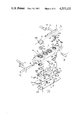
- FIG. 1 is a fragmentary perspective view of a combined combination and key-type lock of a preferred embodiment according to the present invention.
- FIG. 2 is a top view of the present lock, showing the plug of the key-type lock in the opening position;
- FIG. 3 is a top view of the present lock, showing the plug of the key-type lock in the locking position;
- FIG. 4 is a top view of the present lock, showing the plug of the key-type lock in the emergency position;
- FIG. 5 is cross-sectional view of a dial of the present lock
- FIG. 6 is a bottom view of the dial of the compound lock
- FIG. 7 is a top view of a driven disc of the present lock
- FIG. 8 is a front view of FIG. 5;
- FIG. 9 is another front view of the driven disc of the present lock.
- FIG. 10 is a bottom view of FIG. 6;
- FIG. 11 is a front view of a plug of the present lock
- FIG. 12 is a bottom view of the FIG. 9;
- FIG. 13 is another front view of the plug of the present lock
- FIG. 14 is still another front view of the plug of the instant lock
- FIG. 15 is a partial sectional view taken along line B--B of FIG. 2, showing the present lock in an open position;
- FIG. 16 is a sectional view taken along line D--D of FIG. 2, showing the present lock in an open position;
- FIG. 17 is a sectional view taken along line D--D of FIG. 2, showing the present lock in a locked position;
- FIG. 18 is a sectional view taken along line E--E of FIG. 3, showing the present lock in a locked position;
- FIG. 19 is a sectional view showing the present lock in a locked position
- FIG. 20 is a sectional view taken along line E--E of FIG. 3, showing the present key-type lock in a locked position;
- FIG. 21 is a sectional view taken along line H--H of FIG. 4, showing the present lock in a locked position;
- FIG. 22 is a sectional view taken along line F--F of FIG. 4, showing the way to open the present lock while the lock is locked;
- FIG. 23 is a perspective view of the casing (1) reversely positioned
- FIG. 24 is a perspective view of the fixing plate (5) reversely positioned
- FIG. 25 is a sectional view taken along line F--F of FIG. 11, showing notch (407) and protuberance (409);
- FIG. 26 is a perspective view of a decoding rod.
- FIG. 1 shows a fragmentary perspective view of a combined combination and key-type lock of a preferred embodiment according to the present invention.
- the compound lock comprises a combination lock (200) and a key-type lock (400), which may be used individually or jointly.
- the lock comprises a casing (1) which is fastened to a suitcase (not shown) by screwing or riveting.
- the casing (1) is provided with three openings (13) into each of which is mounted a dial (2) of the combination lock (only one of the dial (2) is shown) and an opening (14) into which is mounted a key-type lock (400).
- a locking plate (7) which will lock the lock when engaged with elements (C) or (C') and will open the lock when disengaged from the elements (C) or (C'). It should be noted that only elements C or elements C' are required to adapt for use with the locking plate 7. This depends on the design.
- Each of the elements (C) or (C') is provided with a hook (C1) which will engage with a hook (B) fixedly attached to the cover of the suitcase when the suitcase is locked.
- the locking plate (7) When the correct key of the key-type lock (400) is inserted and the correct numbers of the combination lock (200) are dialed, the locking plate (7) will disengage from the elements (C) or (C') which are in turn forced to go out of the casing (1) in direction (R) or (R'). As a result, the hooks (C1) of the elements (C) or (C') will be separated from the hooks (B) and the suitcase may be opened.
- the locking plate (7) cannot be separated from the elements (C) or (C'), i.e., the suitcase cannot be opened.
- dials (2) of the combination lock (200) are located above the casing (1), thus facilitating the turning of the dials (2) of the combination lock (200).
- At the upper edge of each opening (13) are ten notches (15).
- At each end side of the casing (1) is a slot (16) through which the corresponding element (C) may go into the casing (1) so as to connect with a slot (74) of the locking plate (7).
- each dial (2) of the combination lock (200) is provided with 10 numerals (21).
- At the bottom of each dial (2) are ten teeth (24) arranged in such positions that each of the teeth (24) is aligned with one of the numerals (21).
- Between every two teeth (24) of each dial (2) is a bottomland (25).
- the lower part of each dial (2) is engaged with a ring (11).
- Each dial (2) is rotatably mounted to the casing (1) by inserting a snap ring (3) into circular slot (23) of each dial (2).
- Notches (22) of each dial (2) are used to engage with protuberances (111) of the ring (11) so that the ring (11) may rotate with the dial (2).
- feet (112) of the ring (11) fall into the notches (15) of the casing (1), one of the numerals (21) will align with an indicating line (12) of the casing (1), thus making the alignment of numerals (21) easier.
- each dial (2) under each dial (2) is a driven disc (4) which is provided with two protuberances (41) used to engage with the bottomlands (25) of the dial (2).
- a notch (42) which serves to determine the locking position of the combination lock (200).
- Each driven disc (4) is rotatably mounted in a hole (51) of a fixing plate (5).
- the fixing plate (5) is confined into the casing (1) by columns (18) (shown in FIG. 23) of the casing (1) at the other end. Edges (55) of the fixing plate (5) are engaged with the columns (18) of the casing (1) so that the movement of the fixing plate (5) is limited with a predetermined range.
- a helical spring (6) engages tongue (53) of the fixing plate (5) at one end and is connected to a recess (19) (shown in FIG. 23) of the casing (1) at the other end so that the fixing plate (5) will be forced to go to the right with respect to FIG. 1. Since each driven disc (4) is engaged with a corresponding dial (2), the driven disc (4) will rotate with the dial (2). Consequently, the positions of the notches (42) of the driven discs (4) will be changed when the dial (2) is rotated.
- the locking plate (7) is confined within the casing (1) in a manner such that tongues (72) of the locking plate (7) are positioned into slots (20) (shown in FIG. 23) of the casing (1). Furthermore, one end of a spring (8) is located at the same edge as the two tongues (72) of the locking plate (7) and the other end of the spring (8) is engaged with recess (96) of the base plate (9), so that the locking plate (7) is spring-loaded and may rotate about the axis joining the two tongues (72) of the locking plate (7).
- the protuberances (91) of the base plate (9) are inserted through notches (75) of the locking plate (7).
- protuberances (71) of the locking plate (7) will be closely in contact with the lower surfaces of the driven discs (4).
- the dials (2) are rotated to the positions where all protuberances (71) of the locking plate (7) engage the corresponding notches (42) of the driven discs (4), the locking plate is forced by the spring (8) to go upward.
- the numerals (21) of the dials which are aligned with the indicating lines (12) of the casing (1) are the correct numbers of the combination lock (200).
- the slots (74) will be separated from the elements (C) or (C') and the suitcase may be opened.
- the fixing plate (5) is further provided with a pushing rod (56) which has two arms (57).
- a pushing rod (56) which has two arms (57).
- the locking plate (7) is moved upward and the fixing plate (5) may be pushed to the with respect to FIG. 15.
- the driven discs (4) disengage from the dial (2).
- the two arms (57) of the pushing rod (56) are used to prevent the locking plate (7) from moving downward.
- the numbers of the combination lock (200) may be changed to any desired numbers by turning the dials (2).
- the arms (57) of the pushing rod (56) is prevented by edges (107) of the locking plate (7) to move to the left when either the combination lock (200) or the key-type lock (400) is locked.
- the key-type lock (400) is equipped with a plug (40) which is mounted in the opening (14) of the casing (1).
- the opening (14) is provided with four vertical slots (302).
- the plug (40) is provided with a key hole (401) in the top and three slots (402) arranged longitudinally in its vertical surface.
- plates (60) of the plug (40) are located inside the slots (302) shown in FIG. 23, thereby preventing the plug (40) from turning.
- the plates (60) is forced to withdraw from the slots (302) and the lock (400) may be opened if the combination lock (200) is correctly dialed.
- a circular slot (404) which engages with a spring (50) so as to confine the plug (40) within the casing (1).
- the spring (50) is fixed to the casing (1) by inserting its end (502) into recess (303) of the casing (1) (see FIG. 23).
- the plug (40) further comprises a projection (405) and a hook (406) (see FIGS. 11, 12 and 13) which are inserted into hole (76) of the locking plate (7).
- the projection (405) forces edge (79) of the hole (76) of the locking plate (7) to move downward, thus engaging the slots (74) with the elements (C) or (C') and the suitcase is locked.
- the hook (406) of the plug (40) is a device for preventing the plug (40) from getting out of the casing (1) and ensuring the locking plate (7) to move downward when locked.
- protuberance (501) of the spring (50) When the plug (40) is in the open position, protuberance (501) of the spring (50) will go into a recess (407) (shown in FIG. 10) of the plug (40), thereby giving a feeling for positioning.
- the columns (18) of the casing (1) are used to limit the movement of the fixing plate (5).
- the spring (6) will urge edges (55) of the fixing plate (5) to engage with the columns (18) of the casing (1).
- edges (58) of the fixing plate (5) will contact the columns (18) of the casing (1) and the driven discs (4) will be separated from the dials (2), thus enabling the numbers of the combination lock (200) to be changed.
- the plug (40) is provided with a protuberance (409) which is hampered by edge (79) of the locking plate (7) when the combination lock (200) is opened so that plug (40) can only be rotated to the position shown in FIG. 3 when the combination lock (200) is opened. Only when the combination lock (200) is opened, the locking plate (7) is rotated to such a position that the protuberance (409) of the plug (40) will not be hampered by the edge (79) of the locking plate (7), i.e., the plug (40) may be rotated to the emergency position as shown in FIG. 4.
- the compound lock can still be opened and the correct numbers of the combination lock (200) may be found by the following procedures.
- the hook (406) of the plug (40) will lift edge (80) of the opening (76) of the locking plate (7) while protuberance (405) of the plug (40) will force edge (78) of the opening (76) of the locking plate (7) to go downward, as shown in FIG. 22.
- the combination lock (200) may randomly be rotated so that the chance of exposing the correct numbers of the combination lock (200) may be decreased.
Landscapes
- Lock And Its Accessories (AREA)
Abstract
Description
Claims (1)
Priority Applications (1)
| Application Number | Priority Date | Filing Date | Title |
|---|---|---|---|
| US06/526,286 US4557122A (en) | 1983-08-25 | 1983-08-25 | Combined combination and key-type lock |
Applications Claiming Priority (1)
| Application Number | Priority Date | Filing Date | Title |
|---|---|---|---|
| US06/526,286 US4557122A (en) | 1983-08-25 | 1983-08-25 | Combined combination and key-type lock |
Publications (1)
| Publication Number | Publication Date |
|---|---|
| US4557122A true US4557122A (en) | 1985-12-10 |
Family
ID=24096705
Family Applications (1)
| Application Number | Title | Priority Date | Filing Date |
|---|---|---|---|
| US06/526,286 Expired - Fee Related US4557122A (en) | 1983-08-25 | 1983-08-25 | Combined combination and key-type lock |
Country Status (1)
| Country | Link |
|---|---|
| US (1) | US4557122A (en) |
Cited By (34)
| Publication number | Priority date | Publication date | Assignee | Title |
|---|---|---|---|---|
| US4671088A (en) * | 1985-02-06 | 1987-06-09 | Yan Chan Hong | Combined combination and key-type lock |
| US5237842A (en) * | 1991-12-05 | 1993-08-24 | Sudhaus Schloss- Und Beschlagtechnik Gmbh & Co. | Key and combination lock for luggage |
| US5485734A (en) * | 1993-12-08 | 1996-01-23 | Yang; Kuo-Tsung | Combination lock |
| US5622067A (en) * | 1994-01-27 | 1997-04-22 | Sudhaus Schloss-Und Beschlagtechnik Gmbh & Co. | User-codable magnetic lock |
| US5906124A (en) * | 1998-01-05 | 1999-05-25 | Su; Shun-Chang | Lock assembly |
| GR1003548B (en) * | 1999-10-01 | 2001-03-12 | Combination security mechanism | |
| US6513356B1 (en) * | 2001-11-09 | 2003-02-04 | Ping-Jan Yang | Dual mechanism lock |
| US6516641B1 (en) * | 2001-07-31 | 2003-02-11 | Takigen Manufacturing Co. Ltd. | Door locking handle assembly with built-in combination lock |
| US6550296B2 (en) * | 2001-06-08 | 2003-04-22 | Takigen Manufacturing Co. Ltd. | Door locking handle assembly with built-in combination lock |
| US20030196463A1 (en) * | 2001-03-07 | 2003-10-23 | Takigen Manufacturing Co., Ltd. | Door locking handle assembly |
| US20040011095A1 (en) * | 2002-07-18 | 2004-01-22 | Takigen Manufacturing Co., Ltd. | Door locking handle assembly with built-in combination lock |
| EP1267020A3 (en) * | 2001-06-16 | 2004-04-21 | Sudhaus GmbH & Co | Locking device |
| US20050072196A1 (en) * | 2003-10-06 | 2005-04-07 | Renny Tse-Haw Ling | Combination lock having a second lock mechanism |
| KR100482186B1 (en) * | 2002-01-21 | 2005-04-13 | 다키겐 세이조 가부시키가이샤 | Door locking handle assembly of dual lock type |
| US20050098629A1 (en) * | 2003-11-12 | 2005-05-12 | David Tropp | Method of improving airline luggage inspection |
| US20050154605A1 (en) * | 2003-11-12 | 2005-07-14 | David Tropp | Method of improving airline luggage inspection |
| US7021092B2 (en) | 2003-05-16 | 2006-04-04 | Stanton Concepts Inc. | Multiple function lock |
| US20060248930A1 (en) * | 2005-03-17 | 2006-11-09 | Elles Daniel G | Combination lock with pass-key override |
| US20070193316A1 (en) * | 2006-02-22 | 2007-08-23 | Chien-Yung Huang | Suitcase lock that can be opened either by setting a combination or by a key |
| US7266980B1 (en) * | 2006-05-12 | 2007-09-11 | Min-Tsung Ma | Complex suitcase lock |
| US20070214850A1 (en) * | 2006-03-14 | 2007-09-20 | Min-Tsung Ma | Lock assembly |
| US20070295038A1 (en) * | 2004-03-05 | 2007-12-27 | Yu Chun T | Woven strap lock structure |
| US20080022737A1 (en) * | 2006-07-31 | 2008-01-31 | Ping-Jan Yang | Figure wheel locking device |
| US20080087049A1 (en) * | 2006-10-16 | 2008-04-17 | Eric Lai | Padlocks for holding and securing zipper pulls |
| US20080173050A1 (en) * | 2007-01-18 | 2008-07-24 | Shengde Industries Co., Ltd. | Lock assembly |
| US7424812B2 (en) | 2003-05-16 | 2008-09-16 | Stanton Concepts Inc. | Multiple function lock |
| US20080236212A1 (en) * | 2007-03-30 | 2008-10-02 | Min-Tsung Ma | Zipper lock |
| US7434426B2 (en) | 2003-05-16 | 2008-10-14 | Stanton Concepts Inc. | Multiple function lock |
| US20080314093A1 (en) * | 2007-06-21 | 2008-12-25 | Master Lock Company, Llc | Combination lock |
| US20090139282A1 (en) * | 2006-03-28 | 2009-06-04 | Kabushiki Kaisha Hinomoto Jomae | Dial lock for luggage |
| US20090145178A1 (en) * | 2007-12-07 | 2009-06-11 | Master Lock Company Llc | Combination lock |
| US7694542B2 (en) | 2004-07-22 | 2010-04-13 | Stanton Concepts Inc. | Tool operated combination lock |
| US7712342B2 (en) | 2004-07-22 | 2010-05-11 | Stanton Concepts Inc. | Tool operated combination lock |
| US20110083483A1 (en) * | 2009-10-08 | 2011-04-14 | Ping-Jan Yang | Double-system lock apparatus |
Citations (2)
| Publication number | Priority date | Publication date | Assignee | Title |
|---|---|---|---|---|
| GB2068449A (en) * | 1980-01-31 | 1981-08-12 | Ricouard L A S Sa | Combination cylinder lock |
| US4462232A (en) * | 1982-04-20 | 1984-07-31 | Yang Gwo T | Combination lock for luggage cases |
-
1983
- 1983-08-25 US US06/526,286 patent/US4557122A/en not_active Expired - Fee Related
Patent Citations (2)
| Publication number | Priority date | Publication date | Assignee | Title |
|---|---|---|---|---|
| GB2068449A (en) * | 1980-01-31 | 1981-08-12 | Ricouard L A S Sa | Combination cylinder lock |
| US4462232A (en) * | 1982-04-20 | 1984-07-31 | Yang Gwo T | Combination lock for luggage cases |
Cited By (59)
| Publication number | Priority date | Publication date | Assignee | Title |
|---|---|---|---|---|
| US4671088A (en) * | 1985-02-06 | 1987-06-09 | Yan Chan Hong | Combined combination and key-type lock |
| US5237842A (en) * | 1991-12-05 | 1993-08-24 | Sudhaus Schloss- Und Beschlagtechnik Gmbh & Co. | Key and combination lock for luggage |
| US5485734A (en) * | 1993-12-08 | 1996-01-23 | Yang; Kuo-Tsung | Combination lock |
| US5622067A (en) * | 1994-01-27 | 1997-04-22 | Sudhaus Schloss-Und Beschlagtechnik Gmbh & Co. | User-codable magnetic lock |
| US5906124A (en) * | 1998-01-05 | 1999-05-25 | Su; Shun-Chang | Lock assembly |
| GR1003548B (en) * | 1999-10-01 | 2001-03-12 | Combination security mechanism | |
| US6722169B2 (en) * | 2001-03-07 | 2004-04-20 | Takigen Manufacturing Co. Ltd. | Door locking handle assembly |
| US20030196463A1 (en) * | 2001-03-07 | 2003-10-23 | Takigen Manufacturing Co., Ltd. | Door locking handle assembly |
| US6550296B2 (en) * | 2001-06-08 | 2003-04-22 | Takigen Manufacturing Co. Ltd. | Door locking handle assembly with built-in combination lock |
| EP1267020A3 (en) * | 2001-06-16 | 2004-04-21 | Sudhaus GmbH & Co | Locking device |
| US6516641B1 (en) * | 2001-07-31 | 2003-02-11 | Takigen Manufacturing Co. Ltd. | Door locking handle assembly with built-in combination lock |
| US6513356B1 (en) * | 2001-11-09 | 2003-02-04 | Ping-Jan Yang | Dual mechanism lock |
| KR100482186B1 (en) * | 2002-01-21 | 2005-04-13 | 다키겐 세이조 가부시키가이샤 | Door locking handle assembly of dual lock type |
| US6694786B2 (en) * | 2002-07-18 | 2004-02-24 | Takigen Manufacturing Co. Ltd. | Door locking handle assembly with built-in combination lock |
| US20040011095A1 (en) * | 2002-07-18 | 2004-01-22 | Takigen Manufacturing Co., Ltd. | Door locking handle assembly with built-in combination lock |
| US7424812B2 (en) | 2003-05-16 | 2008-09-16 | Stanton Concepts Inc. | Multiple function lock |
| US7434426B2 (en) | 2003-05-16 | 2008-10-14 | Stanton Concepts Inc. | Multiple function lock |
| US7913526B2 (en) | 2003-05-16 | 2011-03-29 | Stanton Concepts Inc. | Multiple function lock |
| US7021092B2 (en) | 2003-05-16 | 2006-04-04 | Stanton Concepts Inc. | Multiple function lock |
| US7934406B2 (en) | 2003-05-16 | 2011-05-03 | Stanton Concepts Inc. | Multiple function lock |
| US8047027B2 (en) | 2003-05-16 | 2011-11-01 | Stanton Concepts, L.L.C. | Multiple function lock |
| US20050072196A1 (en) * | 2003-10-06 | 2005-04-07 | Renny Tse-Haw Ling | Combination lock having a second lock mechanism |
| US6912880B2 (en) * | 2003-10-06 | 2005-07-05 | Sinox Co., Ltd. | Combination lock having a second lock mechanism |
| USRE45429E1 (en) * | 2003-10-06 | 2015-03-24 | Sinox Co., Ltd. | Combination lock having a second lock mechanism |
| US20050098629A1 (en) * | 2003-11-12 | 2005-05-12 | David Tropp | Method of improving airline luggage inspection |
| US9879447B2 (en) | 2003-11-12 | 2018-01-30 | David Tropp | Method of improving airline luggage inspection |
| US8145576B2 (en) | 2003-11-12 | 2012-03-27 | Iowa Hawkeyes LLC | Method of facilitating screening of airline luggage |
| US10597905B2 (en) | 2003-11-12 | 2020-03-24 | David Tropp | Facilitating security screening of traveler's luggage |
| US7036728B2 (en) | 2003-11-12 | 2006-05-02 | David Tropp | Method of improving airline luggage inspection |
| US7021537B2 (en) | 2003-11-12 | 2006-04-04 | David Tropp | Method of improving airline luggage inspection |
| US20100153123A9 (en) * | 2003-11-12 | 2010-06-17 | David Tropp | Method of improving airline luggage inspection |
| US20050167494A1 (en) * | 2003-11-12 | 2005-08-04 | David Tropp | Method of improving airline luggage inspection |
| US20050154605A1 (en) * | 2003-11-12 | 2005-07-14 | David Tropp | Method of improving airline luggage inspection |
| US20070295038A1 (en) * | 2004-03-05 | 2007-12-27 | Yu Chun T | Woven strap lock structure |
| US7377138B2 (en) * | 2004-03-05 | 2008-05-27 | Chun Te Yu | Woven strap lock structure |
| US7712342B2 (en) | 2004-07-22 | 2010-05-11 | Stanton Concepts Inc. | Tool operated combination lock |
| US7694542B2 (en) | 2004-07-22 | 2010-04-13 | Stanton Concepts Inc. | Tool operated combination lock |
| US20060248930A1 (en) * | 2005-03-17 | 2006-11-09 | Elles Daniel G | Combination lock with pass-key override |
| US7380427B2 (en) * | 2005-03-17 | 2008-06-03 | Samsonite Corporation | Combination lock with pass-key override |
| US20070193316A1 (en) * | 2006-02-22 | 2007-08-23 | Chien-Yung Huang | Suitcase lock that can be opened either by setting a combination or by a key |
| US7290417B1 (en) * | 2006-02-22 | 2007-11-06 | Chien-Yung Huang | Suitcase lock that can be opened either by setting a combination or by a key |
| US20070214850A1 (en) * | 2006-03-14 | 2007-09-20 | Min-Tsung Ma | Lock assembly |
| US20090139282A1 (en) * | 2006-03-28 | 2009-06-04 | Kabushiki Kaisha Hinomoto Jomae | Dial lock for luggage |
| US7266980B1 (en) * | 2006-05-12 | 2007-09-11 | Min-Tsung Ma | Complex suitcase lock |
| US7367207B2 (en) * | 2006-07-31 | 2008-05-06 | Ping-Jan Yang | Figure wheel locking device |
| US20080022737A1 (en) * | 2006-07-31 | 2008-01-31 | Ping-Jan Yang | Figure wheel locking device |
| US20080087049A1 (en) * | 2006-10-16 | 2008-04-17 | Eric Lai | Padlocks for holding and securing zipper pulls |
| US8096150B2 (en) * | 2006-10-16 | 2012-01-17 | The Sun Lock Company Ltd. | Padlocks for holding and securing zipper pulls |
| US7437903B2 (en) * | 2007-01-18 | 2008-10-21 | Shengde Industries Co., Ltd. | Lock assembly |
| US20080173050A1 (en) * | 2007-01-18 | 2008-07-24 | Shengde Industries Co., Ltd. | Lock assembly |
| US20080236212A1 (en) * | 2007-03-30 | 2008-10-02 | Min-Tsung Ma | Zipper lock |
| US20100192641A1 (en) * | 2007-06-21 | 2010-08-05 | Master Lock Company, Llc | Combination lock |
| US8769999B2 (en) | 2007-06-21 | 2014-07-08 | Master Lock Company Llc | Combination lock |
| US20080314093A1 (en) * | 2007-06-21 | 2008-12-25 | Master Lock Company, Llc | Combination lock |
| US8544301B2 (en) | 2007-06-21 | 2013-10-01 | Master Lock Company Llc | Combination lock |
| US20090145178A1 (en) * | 2007-12-07 | 2009-06-11 | Master Lock Company Llc | Combination lock |
| US8539799B2 (en) | 2007-12-07 | 2013-09-24 | Master Lock Company Llc | Combination lock |
| US8113024B2 (en) * | 2009-10-08 | 2012-02-14 | Real Locks & Security Co., Ltd. | Double-system lock apparatus |
| US20110083483A1 (en) * | 2009-10-08 | 2011-04-14 | Ping-Jan Yang | Double-system lock apparatus |
Similar Documents
| Publication | Publication Date | Title |
|---|---|---|
| US4557122A (en) | Combined combination and key-type lock | |
| US4751830A (en) | Push-button padlock with secondary key | |
| US4936894A (en) | Pushbutton lock | |
| US4671088A (en) | Combined combination and key-type lock | |
| US6955069B2 (en) | Door locking handle assembly with built-in combination lock | |
| US8539799B2 (en) | Combination lock | |
| US6904776B1 (en) | Combination lock capable of being opened by a key | |
| US11261622B2 (en) | High security combination padlock with ease of use reset mechanism | |
| CA1145581A (en) | Magnetic key operated hotel door lock | |
| US4767140A (en) | Tubular lock with an adjustable device for two-size setting | |
| EP3199729B1 (en) | High security combination padlock | |
| EP4460609A1 (en) | Object shaped combination padlock | |
| US20040261477A1 (en) | Combination lock | |
| EP0147377A1 (en) | A cylinder lock | |
| US3447348A (en) | Combination locker locks | |
| US20170284127A1 (en) | Zipper padlock with a dual locking system | |
| CN100537986C (en) | combination lock | |
| US5179849A (en) | Steering wheel lock for automobile | |
| US5005384A (en) | Mechanism for a combination padlock | |
| US4838058A (en) | Card lock | |
| US4524592A (en) | Combination lock | |
| US5713226A (en) | Luggage lock | |
| US4956985A (en) | Combination lock mechanism and method | |
| US5839301A (en) | Combination lock | |
| KR101876857B1 (en) | Dial Lock with Easy Password Reset |
Legal Events
| Date | Code | Title | Description |
|---|---|---|---|
| AS | Assignment |
Owner name: YE, CHEAN, CHEN, NO. 139, SEC. 2, CHANGE HSING ROA Free format text: ASSIGNMENT OF ASSIGNORS INTEREST.;ASSIGNOR:HWANG, BLAKE;REEL/FRAME:004797/0566 Effective date: 19871201 Owner name: YE, CHEAN, CHEN, NO. 139, SEC. 2, CHANGE HSING ROA Free format text: ASSIGNMENT OF ASSIGNORS INTEREST;ASSIGNOR:HWANG, BLAKE;REEL/FRAME:004797/0566 Effective date: 19871201 |
|
| FEPP | Fee payment procedure |
Free format text: PAYOR NUMBER ASSIGNED (ORIGINAL EVENT CODE: ASPN); ENTITY STATUS OF PATENT OWNER: SMALL ENTITY |
|
| FPAY | Fee payment |
Year of fee payment: 4 |
|
| FPAY | Fee payment |
Year of fee payment: 8 |
|
| REMI | Maintenance fee reminder mailed | ||
| LAPS | Lapse for failure to pay maintenance fees | ||
| FP | Lapsed due to failure to pay maintenance fee |
Effective date: 19971210 |
|
| STCH | Information on status: patent discontinuation |
Free format text: PATENT EXPIRED DUE TO NONPAYMENT OF MAINTENANCE FEES UNDER 37 CFR 1.362 |