US4556062A - Cardiac stimulator with frequency self-regulation through the electrocardiographic T wave - Google Patents
Cardiac stimulator with frequency self-regulation through the electrocardiographic T wave Download PDFInfo
- Publication number
- US4556062A US4556062A US06/548,775 US54877583A US4556062A US 4556062 A US4556062 A US 4556062A US 54877583 A US54877583 A US 54877583A US 4556062 A US4556062 A US 4556062A
- Authority
- US
- United States
- Prior art keywords
- pacemaker
- sensing
- wave
- signals
- wave signals
- Prior art date
- Legal status (The legal status is an assumption and is not a legal conclusion. Google has not performed a legal analysis and makes no representation as to the accuracy of the status listed.)
- Expired - Fee Related
Links
Images

Classifications
-
- A—HUMAN NECESSITIES
- A61—MEDICAL OR VETERINARY SCIENCE; HYGIENE
- A61N—ELECTROTHERAPY; MAGNETOTHERAPY; RADIATION THERAPY; ULTRASOUND THERAPY
- A61N1/00—Electrotherapy; Circuits therefor
- A61N1/18—Applying electric currents by contact electrodes
- A61N1/32—Applying electric currents by contact electrodes alternating or intermittent currents
- A61N1/36—Applying electric currents by contact electrodes alternating or intermittent currents for stimulation
- A61N1/362—Heart stimulators
- A61N1/365—Heart stimulators controlled by a physiological parameter, e.g. heart potential
- A61N1/36507—Heart stimulators controlled by a physiological parameter, e.g. heart potential controlled by gradient or slope of the heart potential
Definitions
- the invention relates to a cardiac stimulator with frequency self-regulation through the electrocardiographic T wave.
- the object of the invention is first and foremost to determine an algorithm that can be used for the construction of a pacemaker, the frequency of which is regulated in a physiological fashion.
- the said algorithm can be realized in one of the two following forms:
- Both the type A and the type B can be used in pacemakers with atrial and/or ventricular stimulation.
- Detection of the T wave can be effected by the stimulating electrode (in the case of ventricular stimulation) and be discriminated by a filter circuit that separates it from the polarization signals existing at the level of the stimulating electrode. Alternatively, it can be detection (and this applies to all types of stimulation) by an electrode placed on the catheter itself, or on a separate one, situated in the ventricle.
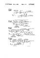
- FIG. 1 represents a VV1 stimulator that utilizes one single ventricular V electrode
- FIG. 2 again represents a VV1 stimulator provided with an amplifier connected to an auxiliary ventricular electrode
- FIG. 3 represents the algorithm applied to a VDD stimulator, that is to say one piloted by the atrial signal and inhibited by the ventricular signal;
- FIG. 4 represents the algorithm applied to an AA1 atrial stimulator utilized when there is a sino-atrial block with satisfacotry atrio-ventricular conduction;
- FIG. 5 shows, as an example, a block diagrammatic arrangement for obtaining a signal proportional to the slope of the T wave
- FIG. 6 shows the above mentioned signal sent to two fixed reference signal comparators, one of which corresponding to a minimum level and the other to a maximum level.
- the block 1 consists of a band pass amplifier able to amplify the depolarization QRS waves and the repolarization T wave (3-150 Hz pass band) detected by the V electrode.
- the block 2 is constituted by a filter that discriminates the said waves from the electrolytic polarization signals present at the electrode-tissue interface after the stimulation impulse.
- the block 3 is a (dV/dt) T wave slope discriminator, from which issues a signal proportional thereto.
- the block 4 represents an impulse generator that can inhibit (input I) and can synchronize or pilot in frequency (input S).
- the block 5 is the amplifier of the ventricular stimulation impulse.
- the ventricular cardiac signal is carried to inhibit (from 1 to the input I of 4) the generator when, for normal VV1 operation, the frequency of the said signal exceeds that of the impulse generator.
- the cardiac signal filtered by 2 is discriminated at 3 in order to obtain the signal proportional to the slope of T which, in turn, pilots the frequency of the impulse generator in accordance with a pre-established and/or programmable rule.
- the frequency of the stimulator will vary in this way proportionally with the slope of the T wave and, therefore, proportionally with the metabolic requirements created by the stress to which the patient is subjected.
- VV1 stimulator is, in FIG. 2, represented by the blocks 1, 4 and 5 to which is added an amplifier 6 connected to an auxiliary ventricular VA electrode having a pass band set for the T wave (3-50 Hz), and this furnishes the signal to the previously described block 3, in turn connected to the input S of the generator 4.
- the operation of the stimulator is identical to that of the one shown in FIG. 1.
- the cardiac signal is picked up by means of a ventricular V electrode with the amplifier 1, through the filter 2 and, therefore, the discriminator 3 of the T wave.
- the intracardiac wave P that is amplified by the amplifier 7 set for this signal (20-200 Hz pass band) is picked up by an atrial electrode A.
- the atrial signal sets in operation a retard circuit (delay means) 8 that reproduces the natural A-V retard (100-200 msec) and emits a signal upon completion of the said retardation.
- the signals forthcoming from 3 and from 8 are utilized by the selection block (selection means) 9 which is set and/or programmed to synchronize the frequency of the generator 4 proportionally with the T wave slope variation and/or to synchronize it with the atrial signal.
- the ventricular signal is again utilized to inhibit the generator 4 (input I) should the frequency of the natural QRS wave exceed that envisaged at 4.
- the impulse amplifier 5 carries the stimulus to the ventricular electrode.
- FIG. 4 an example is given of the application of the algorithm to an atrial AA1 stimulator that is utilized when there is a sino-atrial block with satisfactory atrio-ventricular conduction.
- the signal is passed to an amplifier 6 (having the previously described characteristics) and by this to a discriminator 3 that pilots the impulse generator 4.
- the atrial signal that inhibits the generator 4 when the frequency of the artial wave P exceeds that envisaged at 4, is picked up by the atrial electrode A.
- atrial stimulation through the impulse amplifier 5 proportional to the physical or psychic stress to which the patient is subjected.
- the block 3 which is the core of the system, can be constructed with the combination of various components now in common use in the electronics industry.
- FIG. 5 by way of an example, a block diagrammatic arrangement is shown for obtaining a signal proportional to the slope of the T wave.
- This envisages there being an amplifier 10 provided with a system for automatically regulating the gain in such a way as to obtain an output signal that is always of the same amplitude.
- the signal thus obtained is sent to two fixed reference signal comparators, one corresponding to a minimum level 11 and one to a maximum level 12 of the signal (FIG. 6).
- These furnish two time staggered output signals, X 1 and X 2 , respectively, the former at t 1 and the latter at t 2 , the t 2 -t 1 interval being proportional to the slope of the examined wave.
- the said two signals can be sent to the input of a bistable circuit that will furnish an output signal Y, the duration of which is again proportional to the slope.
- a circuit for quenching the amplifier whereby it be left open only at a time corresponding to that of appearance of the T wave (for example, between 150 and 400 msec after the spike).
Landscapes
- Health & Medical Sciences (AREA)
- Cardiology (AREA)
- Heart & Thoracic Surgery (AREA)
- Life Sciences & Earth Sciences (AREA)
- Engineering & Computer Science (AREA)
- Physiology (AREA)
- Biophysics (AREA)
- Biomedical Technology (AREA)
- Nuclear Medicine, Radiotherapy & Molecular Imaging (AREA)
- Radiology & Medical Imaging (AREA)
- Animal Behavior & Ethology (AREA)
- General Health & Medical Sciences (AREA)
- Public Health (AREA)
- Veterinary Medicine (AREA)
- Electrotherapy Devices (AREA)
Abstract
Description
Claims (22)
Applications Claiming Priority (2)
| Application Number | Priority Date | Filing Date | Title |
|---|---|---|---|
| IT8209537A IT1212617B (en) | 1982-11-05 | 1982-11-05 | SELF-REGULATED HEART STIMULATOR IN FREQUENCY BY MEANS OF THE ELECTROCARDIOGRAPHIC T-WAVE |
| IT9537A/82 | 1982-11-05 |
Publications (1)
| Publication Number | Publication Date |
|---|---|
| US4556062A true US4556062A (en) | 1985-12-03 |
Family
ID=11131827
Family Applications (1)
| Application Number | Title | Priority Date | Filing Date |
|---|---|---|---|
| US06/548,775 Expired - Fee Related US4556062A (en) | 1982-11-05 | 1983-11-04 | Cardiac stimulator with frequency self-regulation through the electrocardiographic T wave |
Country Status (3)
| Country | Link |
|---|---|
| US (1) | US4556062A (en) |
| EP (1) | EP0108731A1 (en) |
| IT (1) | IT1212617B (en) |
Cited By (14)
| Publication number | Priority date | Publication date | Assignee | Title |
|---|---|---|---|---|
| US4719921A (en) * | 1985-08-28 | 1988-01-19 | Raul Chirife | Cardiac pacemaker adaptive to physiological requirements |
| WO1989003705A1 (en) * | 1987-10-27 | 1989-05-05 | Siemens-Elema Ab | Sensing margin detectors for implantable electromedical devices |
| US4907593A (en) * | 1987-05-21 | 1990-03-13 | Biocontrol Technology, Inc. | Adaptation of heart pacing to physical activity |
| US5040534A (en) * | 1989-01-25 | 1991-08-20 | Siemens-Pacesetter, Inc. | Microprocessor controlled rate-responsive pacemaker having automatic rate response threshold adjustment |
| US5040535A (en) * | 1989-01-25 | 1991-08-20 | Siemens-Pacesetter, Inc. | Average amplitude controlled rate-responsive pacemaker having automatically adjustable control parameters |
| US5312455A (en) * | 1993-05-26 | 1994-05-17 | Siemens Pacesetter, Inc. | Programmable window reference generator for use in an implantable cardiac pacemaker |
| US5336242A (en) * | 1993-05-26 | 1994-08-09 | Siemens Pacesetter, Inc. | Band-pass filter for use in a sense amplifier of an implantable cardiac pacer |
| US5476487A (en) * | 1994-12-28 | 1995-12-19 | Pacesetter, Inc. | Autothreshold assessment in an implantable pacemaker |
| EP0934758A1 (en) * | 1997-12-17 | 1999-08-11 | BIOTRONIK Mess- und Therapiegeräte GmbH & Co Ingenieurbüro Berlin | Cardiac Stimulator |
| US6324427B1 (en) | 1999-01-26 | 2001-11-27 | Pacesetter, Inc. | Implantable cardiac stimulation device having T-wave discrimination of fusion events during autocapture/autothreshold assessment |
| US20040002743A1 (en) * | 2002-06-28 | 2004-01-01 | Euljoon Park | Implantable cardiac device having a system for detecting T wave alternan patterns and method |
| US7738956B1 (en) | 2006-01-27 | 2010-06-15 | Pacesetter, Inc. | Pacing schemes for revealing T-wave alternans (TWA) at low to moderate heart rates |
| US7756571B1 (en) | 2005-09-16 | 2010-07-13 | Pacesetter, Inc. | Methods and systems for detecting the presence of T-wave alternans |
| US7881792B1 (en) | 2005-09-16 | 2011-02-01 | Pacesetter, Inc. | Methods and systems for detecting the presence of T-wave alternans |
Families Citing this family (1)
| Publication number | Priority date | Publication date | Assignee | Title |
|---|---|---|---|---|
| SE9701121D0 (en) * | 1997-03-26 | 1997-03-26 | Pacesetter Ab | Implantable heart stimulator |
Citations (9)
| Publication number | Priority date | Publication date | Assignee | Title |
|---|---|---|---|---|
| DE2217235A1 (en) * | 1972-04-11 | 1973-10-18 | Hellige & Co Gmbh F | DEVICE FOR MONITORING THE HEARTY ACTIVITY OF A PATIENT BY AUTOMATIC EVALUATION OF THE ELECTROCARDIOGRAM |
| DE2334341A1 (en) * | 1972-07-13 | 1974-01-31 | Del Mar Eng Lab | ST SEGMENT CALCULATOR FOR THE EXAMINATION OF ELECTROCARDIOGRAMS |
| DE2447052A1 (en) * | 1973-10-04 | 1975-04-17 | Tektronix Inc | METHOD OF DETERMINING THE R-CURVE COMPONENT IN AN ELECTROCARDIOGRAPHIC CURVE WITH P, Q, R, S, AND T-CURVE COMPONENTS |
| US4036690A (en) * | 1974-12-31 | 1977-07-19 | United Kingdom Atomic Energy Authority | Nuclear reactor fuel element assemblies |
| US4228803A (en) * | 1978-06-23 | 1980-10-21 | Credit Du Nord International N.V. | Physiologically adaptive cardiac pacemaker |
| EP0017848A1 (en) * | 1979-04-16 | 1980-10-29 | Vitatron Medical B.V. | Rate adaptive pacemaker |
| WO1981001659A1 (en) * | 1979-12-13 | 1981-06-25 | American Hospital Supply Corp | Programmable digital cardiac pacer |
| EP0080348A1 (en) * | 1981-11-19 | 1983-06-01 | Medtronic, Inc. | Rate adaptive pacer |
| US4423733A (en) * | 1981-08-21 | 1984-01-03 | Gino Grassi | Relay circuit for cardiac pacemaker implant |
Family Cites Families (1)
| Publication number | Priority date | Publication date | Assignee | Title |
|---|---|---|---|---|
| US4136690A (en) * | 1977-10-31 | 1979-01-30 | Del Mar Avionics | Method and apparatus for vector analysis of ECG arrhythmias |
-
1982
- 1982-11-05 IT IT8209537A patent/IT1212617B/en active
-
1983
- 1983-11-03 EP EP83830219A patent/EP0108731A1/en not_active Withdrawn
- 1983-11-04 US US06/548,775 patent/US4556062A/en not_active Expired - Fee Related
Patent Citations (9)
| Publication number | Priority date | Publication date | Assignee | Title |
|---|---|---|---|---|
| DE2217235A1 (en) * | 1972-04-11 | 1973-10-18 | Hellige & Co Gmbh F | DEVICE FOR MONITORING THE HEARTY ACTIVITY OF A PATIENT BY AUTOMATIC EVALUATION OF THE ELECTROCARDIOGRAM |
| DE2334341A1 (en) * | 1972-07-13 | 1974-01-31 | Del Mar Eng Lab | ST SEGMENT CALCULATOR FOR THE EXAMINATION OF ELECTROCARDIOGRAMS |
| DE2447052A1 (en) * | 1973-10-04 | 1975-04-17 | Tektronix Inc | METHOD OF DETERMINING THE R-CURVE COMPONENT IN AN ELECTROCARDIOGRAPHIC CURVE WITH P, Q, R, S, AND T-CURVE COMPONENTS |
| US4036690A (en) * | 1974-12-31 | 1977-07-19 | United Kingdom Atomic Energy Authority | Nuclear reactor fuel element assemblies |
| US4228803A (en) * | 1978-06-23 | 1980-10-21 | Credit Du Nord International N.V. | Physiologically adaptive cardiac pacemaker |
| EP0017848A1 (en) * | 1979-04-16 | 1980-10-29 | Vitatron Medical B.V. | Rate adaptive pacemaker |
| WO1981001659A1 (en) * | 1979-12-13 | 1981-06-25 | American Hospital Supply Corp | Programmable digital cardiac pacer |
| US4423733A (en) * | 1981-08-21 | 1984-01-03 | Gino Grassi | Relay circuit for cardiac pacemaker implant |
| EP0080348A1 (en) * | 1981-11-19 | 1983-06-01 | Medtronic, Inc. | Rate adaptive pacer |
Non-Patent Citations (4)
| Title |
|---|
| IEEE Biomedical Engineering, vol. BME 26, No. 11, Nov. 1979, T Waves . . . , Wolthuis et al., pp. 639 643. * |
| IEEE--Biomedical Engineering, vol. BME-26, No. 11, Nov. 1979, "T-Waves . . . ", Wolthuis et al., pp. 639-643. |
| Soviet Inventions Illustrated, Derwent, Week D22, Jul. 8, 1981, SU P3, p. 8, Cardio Stimulator Controls. * |
| Soviet Inventions Illustrated, Derwent, Week D22, Jul. 8, 1981, SU-P3, p. 8, Cardio--Stimulator Controls. |
Cited By (17)
| Publication number | Priority date | Publication date | Assignee | Title |
|---|---|---|---|---|
| US4719921A (en) * | 1985-08-28 | 1988-01-19 | Raul Chirife | Cardiac pacemaker adaptive to physiological requirements |
| US4907593A (en) * | 1987-05-21 | 1990-03-13 | Biocontrol Technology, Inc. | Adaptation of heart pacing to physical activity |
| WO1989003705A1 (en) * | 1987-10-27 | 1989-05-05 | Siemens-Elema Ab | Sensing margin detectors for implantable electromedical devices |
| US5040534A (en) * | 1989-01-25 | 1991-08-20 | Siemens-Pacesetter, Inc. | Microprocessor controlled rate-responsive pacemaker having automatic rate response threshold adjustment |
| US5040535A (en) * | 1989-01-25 | 1991-08-20 | Siemens-Pacesetter, Inc. | Average amplitude controlled rate-responsive pacemaker having automatically adjustable control parameters |
| US5312455A (en) * | 1993-05-26 | 1994-05-17 | Siemens Pacesetter, Inc. | Programmable window reference generator for use in an implantable cardiac pacemaker |
| US5336242A (en) * | 1993-05-26 | 1994-08-09 | Siemens Pacesetter, Inc. | Band-pass filter for use in a sense amplifier of an implantable cardiac pacer |
| US5476487A (en) * | 1994-12-28 | 1995-12-19 | Pacesetter, Inc. | Autothreshold assessment in an implantable pacemaker |
| EP0934758A1 (en) * | 1997-12-17 | 1999-08-11 | BIOTRONIK Mess- und Therapiegeräte GmbH & Co Ingenieurbüro Berlin | Cardiac Stimulator |
| US6049734A (en) * | 1997-12-17 | 2000-04-11 | Biotronik Mess-Und Therapiegerate Gmbh & Co. Ingenieurburo Berlin | Heart stimulator with AV interval adjustment |
| US6324427B1 (en) | 1999-01-26 | 2001-11-27 | Pacesetter, Inc. | Implantable cardiac stimulation device having T-wave discrimination of fusion events during autocapture/autothreshold assessment |
| US20040002743A1 (en) * | 2002-06-28 | 2004-01-01 | Euljoon Park | Implantable cardiac device having a system for detecting T wave alternan patterns and method |
| US7027867B2 (en) * | 2002-06-28 | 2006-04-11 | Pacesetter, Inc. | Implantable cardiac device having a system for detecting T wave alternan patterns and method |
| US7245968B1 (en) | 2002-06-28 | 2007-07-17 | Pacesetter, Inc. | Implantable cardiac device providing rapid pacing T wave alternan pattern detection and method |
| US7756571B1 (en) | 2005-09-16 | 2010-07-13 | Pacesetter, Inc. | Methods and systems for detecting the presence of T-wave alternans |
| US7881792B1 (en) | 2005-09-16 | 2011-02-01 | Pacesetter, Inc. | Methods and systems for detecting the presence of T-wave alternans |
| US7738956B1 (en) | 2006-01-27 | 2010-06-15 | Pacesetter, Inc. | Pacing schemes for revealing T-wave alternans (TWA) at low to moderate heart rates |
Also Published As
| Publication number | Publication date |
|---|---|
| EP0108731A1 (en) | 1984-05-16 |
| IT8209537A0 (en) | 1982-11-05 |
| IT1212617B (en) | 1989-11-30 |
Similar Documents
| Publication | Publication Date | Title |
|---|---|---|
| US5365932A (en) | Cardiac signal sensing device having sensitivity automatically controlled in response to metabolic demand | |
| US4556062A (en) | Cardiac stimulator with frequency self-regulation through the electrocardiographic T wave | |
| US4779617A (en) | Pacemaker noise rejection system | |
| JP3548177B2 (en) | Waveform discriminator for heart stimulator | |
| US4945909A (en) | Pacemaker with activity-dependent rate limiting | |
| US8195293B2 (en) | Detecting ventricular noise artifacts in an active implantable medical device for pacing, resynchronization and/or defibrillation of the heart | |
| US5188117A (en) | Notch filter noise rejection system in a cardiac control device | |
| US6192275B1 (en) | Adaptive evoked response sensing for automatic capture verification | |
| US6044298A (en) | Optimization of pacing parameters based on measurement of integrated acoustic noise | |
| US4819643A (en) | Method and apparatus for cardioverter/pacer featuring a blanked pacing channel and a rate detect channel with AGC | |
| US4569350A (en) | System for detecting pacer mediated tachycardia | |
| US4766900A (en) | Rate responsive pacing system using the integrated cardiac event potential | |
| US4790317A (en) | Apparatus for recognition and termination of ventricular tachycardia and ventricular fibrillation | |
| US6748272B2 (en) | Atrial interval based heart rate variability diagnostic for cardiac rhythm management system | |
| JP4165684B2 (en) | Automatic threshold sensitivity adjustment for cardiac rhythm management devices | |
| US5269300A (en) | Automatic sensitivity control in an implantable cardiac rhythm management system | |
| US7136705B1 (en) | Method and apparatus for monitoring sensor performance during rate-responsive cardiac stimulation | |
| US5741312A (en) | Pacemaker system and method with improved capture detection and threshold search | |
| CA2264670A1 (en) | Method and apparatus for monitored biphasic cardiac impedance sensing | |
| JPS62137068A (en) | Heart pacemaker adapted to physyiological condition | |
| CA2274846A1 (en) | Implantable cardiac stimulator with capture detection and impedance based autotuning of capture detection | |
| Brandt et al. | Far‐field QRS complex sensing: Prevalence and timing with bipolar atrial leads | |
| US20150066103A1 (en) | Unwanted stimulation detection during cardiac pacing | |
| US9795790B2 (en) | Unwanted stimulation detection during cardiac pacing | |
| JPH09103503A (en) | Induced reaction detecting type heart stimulating apparatus |
Legal Events
| Date | Code | Title | Description |
|---|---|---|---|
| AS | Assignment |
Owner name: GRASSI GINA VIA IMBRIANI, 21- SESTO FIORENTINO (FI Free format text: ASSIGNMENT OF ASSIGNORS INTEREST.;ASSIGNORS:GRASSI, GINO;CAMMILLI, LEONARDO;ALCIDI, LUCIANO;AND OTHERS;REEL/FRAME:004192/0743 Effective date: 19831028 |
|
| AS | Assignment |
Owner name: C.B. BIOELETTRONICA S.R.L., VIALE GALILEO FERRARIS Free format text: ASSIGNMENT OF ASSIGNORS INTEREST.;ASSIGNOR:GRASSI GINO;REEL/FRAME:004496/0446 |
|
| FPAY | Fee payment |
Year of fee payment: 4 |
|
| REMI | Maintenance fee reminder mailed | ||
| LAPS | Lapse for failure to pay maintenance fees | ||
| FP | Lapsed due to failure to pay maintenance fee |
Effective date: 19931205 |
|
| STCH | Information on status: patent discontinuation |
Free format text: PATENT EXPIRED DUE TO NONPAYMENT OF MAINTENANCE FEES UNDER 37 CFR 1.362 |