US4550441A - Vented bag - Google Patents
Vented bag Download PDFInfo
- Publication number
- US4550441A US4550441A US06/632,404 US63240484A US4550441A US 4550441 A US4550441 A US 4550441A US 63240484 A US63240484 A US 63240484A US 4550441 A US4550441 A US 4550441A
- Authority
- US
- United States
- Prior art keywords
- channel
- tube
- bag
- openings
- overlapping
- Prior art date
- Legal status (The legal status is an assumption and is not a legal conclusion. Google has not performed a legal analysis and makes no representation as to the accuracy of the status listed.)
- Expired - Lifetime
Links
Images
Classifications
-
- B—PERFORMING OPERATIONS; TRANSPORTING
- B65—CONVEYING; PACKING; STORING; HANDLING THIN OR FILAMENTARY MATERIAL
- B65D—CONTAINERS FOR STORAGE OR TRANSPORT OF ARTICLES OR MATERIALS, e.g. BAGS, BARRELS, BOTTLES, BOXES, CANS, CARTONS, CRATES, DRUMS, JARS, TANKS, HOPPERS, FORWARDING CONTAINERS; ACCESSORIES, CLOSURES, OR FITTINGS THEREFOR; PACKAGING ELEMENTS; PACKAGES
- B65D33/00—Details of, or accessories for, sacks or bags
- B65D33/01—Ventilation or drainage of bags
Definitions
- This invention pertains to an improvement in a multiwall bag of the so called pinch bottom type and more particularly, a multiwall pinch bottom bag constructed to allow air to escape from a sealed pouch housed inside of the multiwall bag.
- Bags of this type of construction contain a plurality of plies of flexible sheet material, such as paper, laminated to one another in superimposed relation which are formed into a tube having gusseted side-walls interposed between front and back walls, one of which overlaps the other at each bag end.
- One overlapping end in the bag is folded over and sealed against the opposite wall to provide an open ended bag ready for filling, usually with a bulk, granular or powdery material, whereupon the opposite overlapping end is similarly folded over and sealed against the opposite wall thereby to completely seal the packaged material within the bag enclosure.
- the innermost ply was sometimes provided with a moisture impervious plastic coating or an innermost ply of plastic material which was permanently laminated to the innermost paper ply.
- an innermost bag ply of a heat sealable plastic material which is loosely adhered to a contiguous paper ply for manual detachment therefrom and which is heat sealed transversely of the bag at the closed end, the bag closure at said end being otherwise completed by folding over an overlapping wall portion of the outermost plies and sealing against the opposite wall.
- the opposite end of the plastic ply is closed by heat sealing prior to folding over and sealing the overlapping wall portions of the outermost plies at said end.
- the plastic ply is of such length as not to be included in the sealed bag end closures provided by the outermost plies.
- the bag may thus be opened in the outermost plies leaving intact the plastic ply and its contents. Since the plastic ply is only lightly adhered to the contiguous ply, the outer plies may be torn or cut away and peeled off of the plastic ply without rupture thereof for removal of a thus completely sealed and impervious plastic ply container of the packaged material. For removal of the packaged contents without contamination, the exterior of this plastic container may be sterilized and the container slit and its contents discharged under wholly sterile conditions in a sterile atmosphere. Examples of such multiwall bag constructions are completely illustrated and described in U.S. Pat. Nos. 3,807,626; 3,910,488; and 4,088,264; whose disclosures are all incorporated herein by reference.
- U.S. Pat. No. 3,302,859 which relates to a bag having a longitudinal seam with overlapping margins secured together throughout their length, and where one of the margins has a series of vents therein to allow air to escape from the bag.
- the embodiments disclosed in this patent have no means for preventing material in the bag from entering the space between the overlapping margins and, vice-versa, to prevent contaminants from entering the bag from its external environment, through the air vents.
- Holes are punched or die cut in the seam area material on the inside of the seam, that is, on the side of the seam facing the product and two longitudinal beads of a thermoplastic-type of adhesive are used to join the pouch material to form the seam, the adhesive being positioned on opposite sides of the spacer. Air could then travel in the channel along the film overlap between the two beads of adhesive and either out another staggered set of holes provided in the the overlap in the area furthest away from the product, or alternatively, through a heat seal closure which is rendered non-continuous in that area because of the filter material or paper vent strip incorporated into the seam seal.
- the spacer element could be eliminated without the loss of its function by forming the longitudinal seam by overlapping the marginal areas of the plastic liner and adhesively securing spaced portions of the overlap using spaced longitudinal beads of a non-heat responsive type of adhesive along the overlapped areas to form the air channel.
- a thermoplastic adhesive responsive to heat and pressure can be used if care is taken not to adhere the entire marginal overlaps to itself.
- a small hole the size of a pinhole is formed through the inner side of the center of the overlap forming the channel near one end.
- a small hole is also formed through the outer side and near the center of the channel adjacent the other end of the plastic pouch.
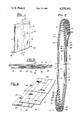
- FIG. 1 is a perspective view of the bag of the present invention
- FIG. 2 is a longitudinal cross-sectional view of the bag of FIG. 1, taken substantially along the plane indicated by line 2--2 of FIG. 1;
- FIG. 3 is a cross-sectional view taken substantially along the plane indicated by line 3--3 of FIG. 2;
- FIG. 4 is a partial perspective view, with portions broken away for purposes of illustration, of the seam area of the inner pouch bag contained within the bag of FIG. 1.
- the bag B shown therein consists essentially of front and rear walls 16 and 17, respectively, each of which includes an innermost ply 10 of a heat sealable thermoplastic material, and three outer plies 11-13, made preferably of heavy kraft paper, although other suitable flexible sheet stock may be employed.
- the bag is gusseted along oppositely disposed sidewalls, as at 14, 15, on opposite sides of relatively wide front and rear walls 16, 17.
- the plastic and contiguous paper plies 10, 11 respectively are substantially flush cut in the front and rear walls and in the gussets, and the outer plies 12, 13, are substantially flush cut coincident therewith in the gussets.
- the outer plies 12, 13 are stepped successively upward in the front wall 16 with respect to plies 10, 11, as shown at 21, 22, and are stepped successively downward with respect thereto in the back wall 17, as at 23, 24.
- the outer plies 12, 13, extend beyond or overlap all plies in the gusset and front wall portions of the bag at the open top end, and thus may be folded over and sealed at spaced spots against the corresponding plies in the front wall or on the outermost ply 13 thereof, for which purpose the overlap area is coated with a thermoplastic adhesive, at spaced spots, as at 25, once the bag B is filled. This leaves the bag open to the atmosphere at spaced locations along the seal for the transmission of air from the interior of the bag B as will be made clear hereinafter.
- the outer plies 12, 13 are correspondingly stepped with respect to the inner plies 10, 11 except in the reverse order as between the back and front walls.
- Closure at the base of the bag to provide the pinch bottom closure 18 is accomplished in two steps.
- the first step consists in applying heat and pressure between the opposite walls of the blank at the lower end, as by means of hot compression rolls or bars. This heat seals the oppositely disposed wall portions of the thermoplastic ply to each other to provide a sealed closure of the ply at the bottom of the bag.
- a thermoplastic adhesive is then applied to the stepped portions of plies 12, 13 as at 35, 36 and the overlapping portions 27, 28 of the outer plies 12, 13 are folded over against the opposite wall of the bag as shown in FIG.
- a rip cord or tear string 40 is interposed as shown in FIG. 2, between ply 12 of front wall 16 and ply 13 of rear wall 17, upon folding over and completing the bag closure in the manner above described.
- Air has a tendency to be entrapped within the product bulk packaged in the thermoplastic ply 10 or the bag pouch such as non-fat dry milk during filling of the ply, or air can be entrapped in the area of the ply above the product at the time the plastic ply is sealed.
- any entrapped air in the ply would be pushed against the interior sides thereof, possibly rupturing the seal on the ply and causing contamination of the ply contents or the air could cause the bags B, when stacked, to assume a higher elevation than normal, which is deleterious, where space constraints are important.
- Air is allowed to escape along a longitudinal seam 50 formed during the production of the inner ply 10.
- the longitudinal seam 50 is formed by overlapping the marginal areas of the inner ply 10 and adhesively securing spaced portions of the overlap using spaced longitudinal beads of adhesive 60, 62 along the overlapped areas to form an air channel 52.
- a single small hole 55 is formed through the inner side 54 in the center of the overlap forming the channel 52 near one end.
- a single small hole 57 is also formed through the outer side 56 near the center of the channel 52 adjacent the other end of the plastic pouch.
- Air is thus permitted to flow from the interior to the exterior of the inner pouch bag 10, which is sealed at opposed ends, through the channel 52 without fear of any substantial amount of material being entrained in the flow because of the use of openings 55, 57 providing minimum exposure to the interior of the pouch.
- the air vented from channel 52 is discharged to the atmosphere by way of the spaces between spots 25, 35, 36 of adhesive connecting ply 13 of front wall 16 to ply 12 and/or 13 of rear wall 17.
- holes 55, 57 which are the size of a pinhole, substantially precludes material in the ply 10 from entering the seam channel 52 and vice-versa, from contaminants entering the ply 10 through the openings.
- sample bags using a pouch bag with pinhole size vents 55, 57 were filled with powdered milk. In five hours, there was enough evacuation of air from the interior of pouch bag 10 to permit stable stacking. In twenty hours, there was complete evacuation and substantially no migration of the powdered milk into the channel 52.
- While one small hole at each end of the channel should be sufficient in most cases to provide proper venting and inhibit flow of bulk material into the channel and admission of external contaminants into the channel, some applications may require a few small holes at each end of the channel. In any event, the size and number of holes at each end of the channel should be sufficient for venting of the inner pouch bag but insufficient to promote flow of bulk material into the channel or admission of external contaminants into the channel.
- vent channel 52 is applied to a plastic pouch inside of a multi-wall paper bag, it will be understood that the invention has application to a plastic pouch standing alone.
Abstract
Description
Claims (7)
Priority Applications (1)
| Application Number | Priority Date | Filing Date | Title |
|---|---|---|---|
| US06/632,404 US4550441A (en) | 1984-07-18 | 1984-07-18 | Vented bag |
Applications Claiming Priority (1)
| Application Number | Priority Date | Filing Date | Title |
|---|---|---|---|
| US06/632,404 US4550441A (en) | 1984-07-18 | 1984-07-18 | Vented bag |
Publications (1)
| Publication Number | Publication Date |
|---|---|
| US4550441A true US4550441A (en) | 1985-10-29 |
Family
ID=24535397
Family Applications (1)
| Application Number | Title | Priority Date | Filing Date |
|---|---|---|---|
| US06/632,404 Expired - Lifetime US4550441A (en) | 1984-07-18 | 1984-07-18 | Vented bag |
Country Status (1)
| Country | Link |
|---|---|
| US (1) | US4550441A (en) |
Cited By (21)
| Publication number | Priority date | Publication date | Assignee | Title |
|---|---|---|---|---|
| US4874620A (en) * | 1986-10-01 | 1989-10-17 | Packaging Concepts, Inc. | Microwavable package incorporating controlled venting |
| US5351828A (en) * | 1989-07-11 | 1994-10-04 | Rolf Becker | Inflatable foil sachet, especially for packaging purposes |
| US5399022A (en) * | 1993-02-25 | 1995-03-21 | Ab Specialty Packaging, Inc. | Venting structure for a multiple ply bag |
| US5553942A (en) * | 1994-03-11 | 1996-09-10 | Robert Bosch Gmbh | Laminate for producing packaging containers |
| US5655842A (en) * | 1993-12-28 | 1997-08-12 | Packs Co., Ltd. | Wrapping device |
| US6170985B1 (en) | 1997-10-15 | 2001-01-09 | Lyle F. Shabram, Jr. | Bag with venting means |
| US20050157961A1 (en) * | 2004-01-21 | 2005-07-21 | Dudley Langston | Vented package |
| US20050281493A1 (en) * | 2004-05-27 | 2005-12-22 | Rkw Ag Rheinische Kunststoffwerke | Plastic bag with overpressure relief |
| US6986605B1 (en) | 2003-04-23 | 2006-01-17 | Exopack-Technology, Llc | Multiwall vented bag, vented bag forming apparatus, and associated methods |
| US7004632B2 (en) | 2003-03-31 | 2006-02-28 | The Glad Products Company | Ventable storage bag |
| US20060045392A1 (en) * | 2004-08-16 | 2006-03-02 | Roger Bannister | Transversely sealed container |
| US20070248291A1 (en) * | 2006-04-20 | 2007-10-25 | Exopack-Thomasville, Llc | Vented plastic bag with filter medium |
| US20080050543A1 (en) * | 2006-08-25 | 2008-02-28 | Alcoa Packaging Llc | Multiple applications of seaming solutions for heat shrunk bands and labels |
| US20080292223A1 (en) * | 2007-05-22 | 2008-11-27 | Roger Bannister | High Strength Multi-Layer Bags |
| US20090159192A1 (en) * | 2007-12-21 | 2009-06-25 | Roger Bannister | Method of Manufacturing a Polypropylene Pinch Bag |
| US20110082019A1 (en) * | 2007-12-21 | 2011-04-07 | Bancroft Bag, Inc. | Method of Manufacturing a Polypropylene Pinch Bag |
| US20150122846A1 (en) * | 2013-11-06 | 2015-05-07 | The Procter & Gamble Company | Flexible containers with vent systems |
| US20150122841A1 (en) * | 2013-11-06 | 2015-05-07 | The Procter & Gamble Company | Easy to empty flexible containers |
| US9694965B2 (en) | 2013-11-06 | 2017-07-04 | The Procter & Gamble Company | Flexible containers having flexible valves |
| US9988190B2 (en) | 2015-04-10 | 2018-06-05 | The Procter & Gamble Company | Flexible containers with biased dispensing |
| US10017300B2 (en) | 2015-04-10 | 2018-07-10 | The Procter & Gamble Company | Flexible containers with product dispensing visibility |
Citations (15)
| Publication number | Priority date | Publication date | Assignee | Title |
|---|---|---|---|---|
| US2593328A (en) * | 1948-07-13 | 1952-04-15 | John W Meaker | Perforated multiple ply bag |
| US3026656A (en) * | 1958-04-22 | 1962-03-27 | Grace W R & Co | Commercial package and method and apparatus for making the same |
| US3092249A (en) * | 1961-03-30 | 1963-06-04 | Chapman Harold Eric | Containers or packages |
| GB961222A (en) * | 1960-05-30 | 1964-06-17 | Natro Cellulosa S P A | Single-ply bags in plastics material |
| GB1016476A (en) * | 1962-06-20 | 1966-01-12 | Sicedison Spa | Plastics bag |
| US3302859A (en) * | 1964-12-21 | 1967-02-07 | Bemis Co Inc | Bag |
| US3370780A (en) * | 1965-10-22 | 1968-02-27 | Continental Can Co | Bag with self-venting back seam |
| US3394871A (en) * | 1966-11-25 | 1968-07-30 | Bemis Co Inc | Bags |
| US3439869A (en) * | 1968-02-08 | 1969-04-22 | Dow Chemical Co | Vented bag |
| US3468471A (en) * | 1965-06-24 | 1969-09-23 | Fritz Linder | Bacteriaproof plastic bag for articles to be sterilized |
| DE1536367A1 (en) * | 1966-07-14 | 1969-12-11 | Windmoeller & Hoelscher | Sacks, in particular made of plastic film |
| US3958749A (en) * | 1974-04-12 | 1976-05-25 | St. Regis Paper Company | Gusseted pinch bottom breakaway pouch bag |
| US4057144A (en) * | 1975-01-17 | 1977-11-08 | Schuster Samuel J | High strength bag for storing materials in sterile condition |
| US4071187A (en) * | 1976-03-15 | 1978-01-31 | Lafleur Arthur E | Valve bag |
| US4470153A (en) * | 1982-03-08 | 1984-09-04 | St. Regis Paper Company | Multiwall pouch bag with vent strip |
-
1984
- 1984-07-18 US US06/632,404 patent/US4550441A/en not_active Expired - Lifetime
Patent Citations (15)
| Publication number | Priority date | Publication date | Assignee | Title |
|---|---|---|---|---|
| US2593328A (en) * | 1948-07-13 | 1952-04-15 | John W Meaker | Perforated multiple ply bag |
| US3026656A (en) * | 1958-04-22 | 1962-03-27 | Grace W R & Co | Commercial package and method and apparatus for making the same |
| GB961222A (en) * | 1960-05-30 | 1964-06-17 | Natro Cellulosa S P A | Single-ply bags in plastics material |
| US3092249A (en) * | 1961-03-30 | 1963-06-04 | Chapman Harold Eric | Containers or packages |
| GB1016476A (en) * | 1962-06-20 | 1966-01-12 | Sicedison Spa | Plastics bag |
| US3302859A (en) * | 1964-12-21 | 1967-02-07 | Bemis Co Inc | Bag |
| US3468471A (en) * | 1965-06-24 | 1969-09-23 | Fritz Linder | Bacteriaproof plastic bag for articles to be sterilized |
| US3370780A (en) * | 1965-10-22 | 1968-02-27 | Continental Can Co | Bag with self-venting back seam |
| DE1536367A1 (en) * | 1966-07-14 | 1969-12-11 | Windmoeller & Hoelscher | Sacks, in particular made of plastic film |
| US3394871A (en) * | 1966-11-25 | 1968-07-30 | Bemis Co Inc | Bags |
| US3439869A (en) * | 1968-02-08 | 1969-04-22 | Dow Chemical Co | Vented bag |
| US3958749A (en) * | 1974-04-12 | 1976-05-25 | St. Regis Paper Company | Gusseted pinch bottom breakaway pouch bag |
| US4057144A (en) * | 1975-01-17 | 1977-11-08 | Schuster Samuel J | High strength bag for storing materials in sterile condition |
| US4071187A (en) * | 1976-03-15 | 1978-01-31 | Lafleur Arthur E | Valve bag |
| US4470153A (en) * | 1982-03-08 | 1984-09-04 | St. Regis Paper Company | Multiwall pouch bag with vent strip |
Cited By (28)
| Publication number | Priority date | Publication date | Assignee | Title |
|---|---|---|---|---|
| US4874620A (en) * | 1986-10-01 | 1989-10-17 | Packaging Concepts, Inc. | Microwavable package incorporating controlled venting |
| US5351828A (en) * | 1989-07-11 | 1994-10-04 | Rolf Becker | Inflatable foil sachet, especially for packaging purposes |
| US5399022A (en) * | 1993-02-25 | 1995-03-21 | Ab Specialty Packaging, Inc. | Venting structure for a multiple ply bag |
| US5655842A (en) * | 1993-12-28 | 1997-08-12 | Packs Co., Ltd. | Wrapping device |
| US5839832A (en) * | 1993-12-28 | 1998-11-24 | Packs Co. Ltd. | Wrapping device |
| US5553942A (en) * | 1994-03-11 | 1996-09-10 | Robert Bosch Gmbh | Laminate for producing packaging containers |
| US6170985B1 (en) | 1997-10-15 | 2001-01-09 | Lyle F. Shabram, Jr. | Bag with venting means |
| US7004632B2 (en) | 2003-03-31 | 2006-02-28 | The Glad Products Company | Ventable storage bag |
| US6986605B1 (en) | 2003-04-23 | 2006-01-17 | Exopack-Technology, Llc | Multiwall vented bag, vented bag forming apparatus, and associated methods |
| US20050157961A1 (en) * | 2004-01-21 | 2005-07-21 | Dudley Langston | Vented package |
| US20050281493A1 (en) * | 2004-05-27 | 2005-12-22 | Rkw Ag Rheinische Kunststoffwerke | Plastic bag with overpressure relief |
| US7927015B2 (en) | 2004-05-27 | 2011-04-19 | Jürgen Heinemeier | Plastic bag with overpressure relief |
| US8371752B2 (en) | 2004-05-27 | 2013-02-12 | Juergen Heinemeier | Plastic bag with overpressure relief |
| US20110188786A1 (en) * | 2004-05-27 | 2011-08-04 | Heinemeier Juergen | Plastic Bag with Overpressure Relief |
| US20060045392A1 (en) * | 2004-08-16 | 2006-03-02 | Roger Bannister | Transversely sealed container |
| US20070248291A1 (en) * | 2006-04-20 | 2007-10-25 | Exopack-Thomasville, Llc | Vented plastic bag with filter medium |
| US20080050543A1 (en) * | 2006-08-25 | 2008-02-28 | Alcoa Packaging Llc | Multiple applications of seaming solutions for heat shrunk bands and labels |
| US7794147B2 (en) * | 2006-08-25 | 2010-09-14 | Reynolds Packaging Llc | Multiple applications of seaming solutions for heat shrunk bands and labels |
| US20080292223A1 (en) * | 2007-05-22 | 2008-11-27 | Roger Bannister | High Strength Multi-Layer Bags |
| US20110082019A1 (en) * | 2007-12-21 | 2011-04-07 | Bancroft Bag, Inc. | Method of Manufacturing a Polypropylene Pinch Bag |
| US20090159192A1 (en) * | 2007-12-21 | 2009-06-25 | Roger Bannister | Method of Manufacturing a Polypropylene Pinch Bag |
| US20150122846A1 (en) * | 2013-11-06 | 2015-05-07 | The Procter & Gamble Company | Flexible containers with vent systems |
| US20150122841A1 (en) * | 2013-11-06 | 2015-05-07 | The Procter & Gamble Company | Easy to empty flexible containers |
| US9694965B2 (en) | 2013-11-06 | 2017-07-04 | The Procter & Gamble Company | Flexible containers having flexible valves |
| US9850046B2 (en) * | 2013-11-06 | 2017-12-26 | The Procter & Gamble Company | Flexible containers with vent systems |
| US10138049B2 (en) | 2013-11-06 | 2018-11-27 | The Procter & Gamble Company | Flexible containers having flexible valves |
| US9988190B2 (en) | 2015-04-10 | 2018-06-05 | The Procter & Gamble Company | Flexible containers with biased dispensing |
| US10017300B2 (en) | 2015-04-10 | 2018-07-10 | The Procter & Gamble Company | Flexible containers with product dispensing visibility |
Similar Documents
| Publication | Publication Date | Title |
|---|---|---|
| US4470153A (en) | Multiwall pouch bag with vent strip | |
| US4550441A (en) | Vented bag | |
| US3807626A (en) | Gusseted pinch bottom breakaway pouch bag | |
| US4759643A (en) | Self-sealing envelope | |
| US4088264A (en) | Multiwall pouch bags for detached packaging of commodities | |
| US6986605B1 (en) | Multiwall vented bag, vented bag forming apparatus, and associated methods | |
| US6279297B1 (en) | Process for the production of a hermetic recloseable package of flexible material | |
| US3302859A (en) | Bag | |
| US4637063A (en) | Reclosable bag with sealed laminated liner and method | |
| US3194471A (en) | Bulk container device | |
| US3910488A (en) | Gusseted pinch bottom breakaway pouch bag | |
| US6539691B2 (en) | Flexible package with sealed edges and easy to open mouth | |
| US20060045392A1 (en) | Transversely sealed container | |
| US6092717A (en) | Tubular container with independently openable compartments | |
| US8371752B2 (en) | Plastic bag with overpressure relief | |
| EP0092885B1 (en) | A plastic bag with gusset folds and perforations | |
| US3738567A (en) | Draw band closure bag | |
| US3687356A (en) | Gusseted type bags | |
| US3349993A (en) | Package | |
| JPH11342958A (en) | Rollable, reclosable pouch | |
| EP0126816A1 (en) | Bags, particularly multiwall bags | |
| US3085737A (en) | Bag with interrupted longitudinal seam | |
| CA2214738A1 (en) | Gussetted flexible package with easy open folded mouth and adhesive strip for reclosing the mouth after opening | |
| US3047206A (en) | Closure means | |
| US4685148A (en) | Square ended valve bag |
Legal Events
| Date | Code | Title | Description |
|---|---|---|---|
| AS | Assignment |
Owner name: ST. REGIS PAPER COMPANY, WEST NYACK ROAD, WEST NYA Free format text: ASSIGNMENT OF ASSIGNORS INTEREST.;ASSIGNOR:KEPPEL, STEPHEN C.;REEL/FRAME:004289/0892 Effective date: 19840713 Owner name: ST. REGIS PAPER COMPANY,NEW YORK Free format text: ASSIGNMENT OF ASSIGNORS INTEREST;ASSIGNOR:KEPPEL, STEPHEN C.;REEL/FRAME:004289/0892 Effective date: 19840713 |
|
| STCF | Information on status: patent grant |
Free format text: PATENTED CASE |
|
| AS | Assignment |
Owner name: STONE BROWN PAPER, INC., A CORP. OF DE. Free format text: ASSIGNMENT OF ASSIGNORS INTEREST.;ASSIGNOR:CHAMPION INTERNATIONAL CORPORATION, A CORP.OF N.Y.;REEL/FRAME:004680/0410 Effective date: 19860707 Owner name: CHAMPION INTERNATIONAL CORPORATION Free format text: MERGER;ASSIGNOR:ST. REGIS CORPORATION 1/28/85;REEL/FRAME:004679/0807 Effective date: 19850128 |
|
| AS | Assignment |
Owner name: STONE CONTAINER CORPORATION Free format text: MERGER;ASSIGNORS:STONE CONTAINER CORPORATION, A CORP. OF IL, (MERGED INTO);S.C.C. MERGER CORPORATION, A CORP. OF DE, (CHANGED TO);REEL/FRAME:004893/0153 Effective date: 19870515 Owner name: STONE CONTAINER CORPORATION Free format text: MERGER;ASSIGNOR:STONE BROWN PAPERS, INC., A DE CORP., (MERGED INTO);REEL/FRAME:004893/0167 Effective date: 19861222 |
|
| FEPP | Fee payment procedure |
Free format text: PAYOR NUMBER ASSIGNED (ORIGINAL EVENT CODE: ASPN); ENTITY STATUS OF PATENT OWNER: LARGE ENTITY |
|
| FPAY | Fee payment |
Year of fee payment: 4 |
|
| FEPP | Fee payment procedure |
Free format text: PAYER NUMBER DE-ASSIGNED (ORIGINAL EVENT CODE: RMPN); ENTITY STATUS OF PATENT OWNER: LARGE ENTITY |
|
| FPAY | Fee payment |
Year of fee payment: 8 |
|
| FPAY | Fee payment |
Year of fee payment: 12 |
|
| AS | Assignment |
Owner name: DEUTSCHE BANK TRUST COMPANY AMERICAS, NEW JERSEY Free format text: SECURITY INTEREST;ASSIGNORS:SMURFIT-STONE CONTAINER ENTERPRISES, INC.;SMURFIT-STONE CONTAINER CORPORATION;REEL/FRAME:016145/0201 Effective date: 20041101 Owner name: DEUTSCHE BANK TRUST COMPANY AMERICAS,NEW JERSEY Free format text: SECURITY INTEREST;ASSIGNORS:SMURFIT-STONE CONTAINER ENTERPRISES, INC.;SMURFIT-STONE CONTAINER CORPORATION;REEL/FRAME:016145/0201 Effective date: 20041101 |