US4545064A - X-ray tube rotor mounting - Google Patents
X-ray tube rotor mounting Download PDFInfo
- Publication number
- US4545064A US4545064A US06/546,616 US54661683A US4545064A US 4545064 A US4545064 A US 4545064A US 54661683 A US54661683 A US 54661683A US 4545064 A US4545064 A US 4545064A
- Authority
- US
- United States
- Prior art keywords
- bearing
- anode
- envelope
- central bore
- mounting
- Prior art date
- Legal status (The legal status is an assumption and is not a legal conclusion. Google has not performed a legal analysis and makes no representation as to the accuracy of the status listed.)
- Expired - Fee Related
Links
- 239000012212 insulator Substances 0.000 claims description 3
- 230000004048 modification Effects 0.000 claims 1
- 238000012986 modification Methods 0.000 claims 1
- 238000003475 lamination Methods 0.000 description 5
- 230000000712 assembly Effects 0.000 description 2
- 238000000429 assembly Methods 0.000 description 2
- 238000005219 brazing Methods 0.000 description 2
- 239000000919 ceramic Substances 0.000 description 2
- 238000010276 construction Methods 0.000 description 2
- 238000000034 method Methods 0.000 description 2
- 230000000717 retained effect Effects 0.000 description 2
- 125000006850 spacer group Chemical group 0.000 description 2
- 241000555745 Sciuridae Species 0.000 description 1
- 238000010420 art technique Methods 0.000 description 1
- 230000005540 biological transmission Effects 0.000 description 1
- 229910000833 kovar Inorganic materials 0.000 description 1
- 229910001220 stainless steel Inorganic materials 0.000 description 1
- 239000010935 stainless steel Substances 0.000 description 1
- 238000003466 welding Methods 0.000 description 1
Images

Classifications
-
- H—ELECTRICITY
- H01—ELECTRIC ELEMENTS
- H01J—ELECTRIC DISCHARGE TUBES OR DISCHARGE LAMPS
- H01J35/00—X-ray tubes
- H01J35/02—Details
- H01J35/04—Electrodes ; Mutual position thereof; Constructional adaptations therefor
- H01J35/08—Anodes; Anti cathodes
- H01J35/10—Rotary anodes; Arrangements for rotating anodes; Cooling rotary anodes
- H01J35/101—Arrangements for rotating anodes, e.g. supporting means, means for greasing, means for sealing the axle or means for shielding or protecting the driving
- H01J35/1017—Bearings for rotating anodes
- H01J35/1024—Rolling bearings
-
- H—ELECTRICITY
- H01—ELECTRIC ELEMENTS
- H01J—ELECTRIC DISCHARGE TUBES OR DISCHARGE LAMPS
- H01J2235/00—X-ray tubes
- H01J2235/10—Drive means for anode (target) substrate
- H01J2235/1026—Means (motors) for driving the target (anode)
- H01J2235/1033—Means (motors) for driving the target (anode) mounted within the vacuum vessel
-
- H—ELECTRICITY
- H01—ELECTRIC ELEMENTS
- H01J—ELECTRIC DISCHARGE TUBES OR DISCHARGE LAMPS
- H01J2235/00—X-ray tubes
- H01J2235/10—Drive means for anode (target) substrate
- H01J2235/1093—Measures for preventing vibration
Definitions
- This invention relates to a unique mounting for rotating anode assemblies in x-ray tubes. More particularly, this invention relates to a rotating anode x-ray tube wherein the anode shaft assembly is supported by a ball bearing at each end of the supporting shaft.
- the present invention discloses a mounting for rotating anodes in an x-ray tube where the anode is mounted on a hollow assembly including a motor rotor and is supported by two bearings with one bearing secured against axial movement by a threaded fastener engaging a threaded stud projecting from an end wall of the x-ray tube envelope.
- FIG. 1 is a section view of the x-ray tube showing the environment of the present invention.
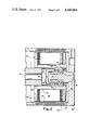
- FIG. 2 is an enlarged view of the rotor end of the tube of FIG. 1 showing details of the present invention.
- the rotor end of tube envelope 10 is preferably formed by positioning laminations 22 on sleeve 24 and brazing an end wall 20, preferably of 304L non-magnetic stainless steel, to laminations 22 and stud 28 to retain stud 28. This results in a relatively inaccessible bearing mounting location on stud 28.
- the rotor mounting of this invention overcomes this relative inaccessibility, however, as will be later described.
- the tube envelope 10 is further made up of a cylindrical wall 32 carrying a conventional x-ray transparent window 34.
- the vacuum integrity of the tube envelope is completed by an anode end plate 36 through which an anode connector 38 and a cathode connector 40 project.
- An anode insulator 42 is mounted on end plate 36 and also forms a bearing mounting. Electrical connection to the anode is made by means of wire connector 44 which is trapped below a lip 46 of a metallic spring cup 48 which permits current to flow through a bearing 50 and a shaft 52 to anode 16. Bearing 50 is retained by a snap ring 54 on the end of shaft 52.
- Anode 16 is electrically isolated from rotor 18 by ceramic spacer 56.
- a bearing 58 is retained in rotor 18 by snap ring 60.
- Bearing 58 and snap ring 60 are carried by a sleeve 62, which is preferably formed of Kovar to enable its attachment to a ceramic spacer 56 by brazing.
- a set of rotor laminations 64 form a squirrel cage construction with a pair of end rings 66 and a rotor balancing weight 68.
- the rotor laminations 64, end rings 66, and balancing weight 68 are carried by a rotor sleeve insert 70 which is secured to sleeve 62.
- Bearing 58 is axially positioned by a shoulder 72 on stud 28.
- a nut 74 holds bearing 58 against shoulder 72.
- Nut 74 carries a slotted cap or head 76 which is secured thereto.
- an equivalent part may be formed corresponding to nut 74 and cap 76 which has internal threads to engage threaded distal end 30 of stud 28 and further has an appropriate configuration on end 78 to receive torque delivered by a tool (such as screw or nut driver) through bore 14.
- nut 74 is loosely inserted into the rotor end of assembly 12.
- Bearing 58 and snap ring 60 are then installed, loosely retaining nut 74.
- Assembly 12 is then loaded into tube envelope 10 which may be complete except for end plate 36 and its respectively attached parts.
- a screw driver (or other appropriate tool) is inserted through central bore 14 to engage slot 80 in cap 76.
- any appropriate configuration between a driving tool and cap 76 may be provided at end 78 to permit torque transmission from the tool to cap 76.
- Cap 76 is then threaded onto and secured to stud 28.
- end wall 36 with its associated parts is then joined with the remainder of envelope 10 in a vacuum-tight relationship, as, for example, by Heliarc welding.
- Insulator 42 engages bearing 50 providing a bearing mounting which prevents radial movement, but allows axial movement of bearing 50 to accommodate thermal expansion of assembly 12 which occurs during normal tube operation.
Landscapes
- X-Ray Techniques (AREA)
Abstract
Description
Claims (11)
Priority Applications (1)
| Application Number | Priority Date | Filing Date | Title |
|---|---|---|---|
| US06/546,616 US4545064A (en) | 1983-10-28 | 1983-10-28 | X-ray tube rotor mounting |
Applications Claiming Priority (2)
| Application Number | Priority Date | Filing Date | Title |
|---|---|---|---|
| US06/546,616 US4545064A (en) | 1983-10-28 | 1983-10-28 | X-ray tube rotor mounting |
| EP85108686A EP0229192A1 (en) | 1985-07-11 | 1985-07-11 | X-ray tube rotor mounting |
Publications (1)
| Publication Number | Publication Date |
|---|---|
| US4545064A true US4545064A (en) | 1985-10-01 |
Family
ID=26096966
Family Applications (1)
| Application Number | Title | Priority Date | Filing Date |
|---|---|---|---|
| US06/546,616 Expired - Fee Related US4545064A (en) | 1983-10-28 | 1983-10-28 | X-ray tube rotor mounting |
Country Status (1)
| Country | Link |
|---|---|
| US (1) | US4545064A (en) |
Cited By (7)
| Publication number | Priority date | Publication date | Assignee | Title |
|---|---|---|---|---|
| US4866748A (en) * | 1988-08-15 | 1989-09-12 | Varian Associates, Inc. | Rotor structure brazed joint |
| US4964148A (en) * | 1987-11-30 | 1990-10-16 | Meicor, Inc. | Air cooled metal ceramic x-ray tube construction |
| US5056126A (en) * | 1987-11-30 | 1991-10-08 | Medical Electronic Imaging Corporation | Air cooled metal ceramic x-ray tube construction |
| US5534747A (en) * | 1994-05-13 | 1996-07-09 | Litton Systems, Inc. | Variable focus electron gun assembly with ceramic spacers |
| US5978447A (en) * | 1997-11-11 | 1999-11-02 | Picker International, Inc. | X-ray tube straddle bearing assembly |
| US20130070903A1 (en) * | 2009-09-30 | 2013-03-21 | Koninklijke Philips Electronics N.V. | Balancing of the rotary anode of an x-ray tube |
| US9874245B2 (en) | 2015-12-07 | 2018-01-23 | Hamilton Sundstrand Corporation | Bearing liners for use within light alloy housings |
Citations (6)
| Publication number | Priority date | Publication date | Assignee | Title |
|---|---|---|---|---|
| US2216888A (en) * | 1939-07-19 | 1940-10-08 | Machlett Lab Inc | X-ray tube |
| US2230857A (en) * | 1939-05-06 | 1941-02-04 | Gen Electric X Ray Corp | Bearing |
| US4024424A (en) * | 1974-11-27 | 1977-05-17 | U.S. Philips Corporation | Rotary-anode X-ray tube |
| US4316129A (en) * | 1977-11-02 | 1982-02-16 | The Machlett Laboratories, Incorporated | X-Ray tube control system |
| US4326144A (en) * | 1979-04-03 | 1982-04-20 | Siemens Aktiengesellschaft | Rotating anode x-ray tube |
| US4413356A (en) * | 1978-10-16 | 1983-11-01 | U.S. Philips Corporation | Flat rotary-anode X-ray tube |
-
1983
- 1983-10-28 US US06/546,616 patent/US4545064A/en not_active Expired - Fee Related
Patent Citations (6)
| Publication number | Priority date | Publication date | Assignee | Title |
|---|---|---|---|---|
| US2230857A (en) * | 1939-05-06 | 1941-02-04 | Gen Electric X Ray Corp | Bearing |
| US2216888A (en) * | 1939-07-19 | 1940-10-08 | Machlett Lab Inc | X-ray tube |
| US4024424A (en) * | 1974-11-27 | 1977-05-17 | U.S. Philips Corporation | Rotary-anode X-ray tube |
| US4316129A (en) * | 1977-11-02 | 1982-02-16 | The Machlett Laboratories, Incorporated | X-Ray tube control system |
| US4413356A (en) * | 1978-10-16 | 1983-11-01 | U.S. Philips Corporation | Flat rotary-anode X-ray tube |
| US4326144A (en) * | 1979-04-03 | 1982-04-20 | Siemens Aktiengesellschaft | Rotating anode x-ray tube |
Cited By (8)
| Publication number | Priority date | Publication date | Assignee | Title |
|---|---|---|---|---|
| US4964148A (en) * | 1987-11-30 | 1990-10-16 | Meicor, Inc. | Air cooled metal ceramic x-ray tube construction |
| US5056126A (en) * | 1987-11-30 | 1991-10-08 | Medical Electronic Imaging Corporation | Air cooled metal ceramic x-ray tube construction |
| US4866748A (en) * | 1988-08-15 | 1989-09-12 | Varian Associates, Inc. | Rotor structure brazed joint |
| US5534747A (en) * | 1994-05-13 | 1996-07-09 | Litton Systems, Inc. | Variable focus electron gun assembly with ceramic spacers |
| US5978447A (en) * | 1997-11-11 | 1999-11-02 | Picker International, Inc. | X-ray tube straddle bearing assembly |
| US20130070903A1 (en) * | 2009-09-30 | 2013-03-21 | Koninklijke Philips Electronics N.V. | Balancing of the rotary anode of an x-ray tube |
| US8983037B2 (en) * | 2009-09-30 | 2015-03-17 | Koninklijke Philips N.V. | Balancing of the rotary anode of an X-ray tube |
| US9874245B2 (en) | 2015-12-07 | 2018-01-23 | Hamilton Sundstrand Corporation | Bearing liners for use within light alloy housings |
Similar Documents
| Publication | Publication Date | Title |
|---|---|---|
| EP0653773B1 (en) | X-ray target | |
| US5548629A (en) | Rotary cathode x-ray tube equipment | |
| US4545064A (en) | X-ray tube rotor mounting | |
| US4024424A (en) | Rotary-anode X-ray tube | |
| EP0351225A3 (en) | A bearing assembly for a rotating anode X-ray tube device | |
| EP1292964B1 (en) | Drive assembly for an x-ray tube having a rotating anode | |
| US5838763A (en) | X-ray tube with a plain bearing | |
| US5654999A (en) | Liquid metal plain bearing | |
| JPS60160552A (en) | X-ray tube with spiral groove bearing | |
| KR0171237B1 (en) | Method of manufacturing rotating anode type x-ray tube | |
| US4866748A (en) | Rotor structure brazed joint | |
| US4413356A (en) | Flat rotary-anode X-ray tube | |
| US20050160588A1 (en) | Integrated component mounting system | |
| US4969172A (en) | X-ray tube rotor structure | |
| US4519093A (en) | Rotary anode X-ray tube | |
| JP4409855B2 (en) | Rotating anode for X-ray tube using interference fit | |
| US3956653A (en) | Rotating anode X-ray tube | |
| EP0229192A1 (en) | X-ray tube rotor mounting | |
| US6074165A (en) | Vacuum pump with magnetic bearing system and back-up bearings | |
| JPH07114543B2 (en) | Electric retarder for vehicles | |
| US5592525A (en) | Method for making a rotating anode with an integral shaft | |
| EP2269209B1 (en) | Ball bearing design temperature compensating x-ray tube bearing | |
| US2641132A (en) | Gyroscopic rotor frame | |
| US4822256A (en) | Bearing support for spherical pumps | |
| US5345492A (en) | Rotating anode x-ray tube |
Legal Events
| Date | Code | Title | Description |
|---|---|---|---|
| AS | Assignment |
Owner name: LITTON SYSTEMS, INC., 360 NORTH CRESCENT DRIVE, BE Free format text: ASSIGNMENT OF ASSIGNORS INTEREST.;ASSIGNOR:KLOSTERMANN, HEINRICH F.;REEL/FRAME:004189/0644 Effective date: 19831018 |
|
| AS | Assignment |
Owner name: KLOSTERMANN, HEINRICH F., 1326 HOOVER STREET, APT. Free format text: ASSIGNMENT OF ASSIGNORS INTEREST.;ASSIGNOR:LITTON SYSTEMS, INC.;REEL/FRAME:004632/0952 Effective date: 19850829 Owner name: KLOSTERMANN, HEINRICH F.,CALIFORNIA Free format text: ASSIGNMENT OF ASSIGNORS INTEREST;ASSIGNOR:LITTON SYSTEMS, INC.;REEL/FRAME:004632/0952 Effective date: 19850829 |
|
| AS | Assignment |
Owner name: MEDICAL ELECTRONIC IMAGING CORPORATION, A CORP. OF Free format text: ASSIGNMENT OF ASSIGNORS INTEREST.;ASSIGNOR:KLOSTERMANN, HEINRICH F.;REEL/FRAME:005011/0287 Effective date: 19860730 |
|
| REMI | Maintenance fee reminder mailed | ||
| LAPS | Lapse for failure to pay maintenance fees | ||
| STCH | Information on status: patent discontinuation |
Free format text: PATENT EXPIRED DUE TO NONPAYMENT OF MAINTENANCE FEES UNDER 37 CFR 1.362 |
|
| FP | Lapsed due to failure to pay maintenance fee |
Effective date: 19891001 |
|
| AS | Assignment |
Owner name: MEICOR, INC., A CORP. OF DE, DELAWARE Free format text: CHANGE OF NAME;ASSIGNOR:MEDICAL ELECTRONIC IMAGING CORPORATION, A CORP. OF DE;REEL/FRAME:005600/0014 Effective date: 19880107 Owner name: MEICOR, INC., A CORP. OF DE, DELAWARE Free format text: ASSIGNOR QUIT CLAIMS AND TRANSFERS ALL RIGHT AND TITLE TO SAID ASSIGNEE.;ASSIGNOR:KLOSTERMANN, HEINRICH F.;REEL/FRAME:005600/0005 Effective date: 19900501 |
|
| AS | Assignment |
Owner name: THERATRONICS INTERNATIONAL LIMITED, CANADA Free format text: ASSIGNMENT OF ASSIGNORS INTEREST.;ASSIGNOR:MEICOR, INC., DE CORP.;REEL/FRAME:006046/0595 Effective date: 19910901 |