US4544252A - Apparatus for displaying information in camera view finder - Google Patents
Apparatus for displaying information in camera view finder Download PDFInfo
- Publication number
- US4544252A US4544252A US06/585,247 US58524784A US4544252A US 4544252 A US4544252 A US 4544252A US 58524784 A US58524784 A US 58524784A US 4544252 A US4544252 A US 4544252A
- Authority
- US
- United States
- Prior art keywords
- light
- light emission
- display
- display member
- regions
- Prior art date
- Legal status (The legal status is an assumption and is not a legal conclusion. Google has not performed a legal analysis and makes no representation as to the accuracy of the status listed.)
- Expired - Lifetime
Links
Images

Classifications
-
- G—PHYSICS
- G03—PHOTOGRAPHY; CINEMATOGRAPHY; ANALOGOUS TECHNIQUES USING WAVES OTHER THAN OPTICAL WAVES; ELECTROGRAPHY; HOLOGRAPHY
- G03B—APPARATUS OR ARRANGEMENTS FOR TAKING PHOTOGRAPHS OR FOR PROJECTING OR VIEWING THEM; APPARATUS OR ARRANGEMENTS EMPLOYING ANALOGOUS TECHNIQUES USING WAVES OTHER THAN OPTICAL WAVES; ACCESSORIES THEREFOR
- G03B17/00—Details of cameras or camera bodies; Accessories therefor
- G03B17/18—Signals indicating condition of a camera member or suitability of light
- G03B17/20—Signals indicating condition of a camera member or suitability of light visible in viewfinder
Definitions
- the present invention relates to an apparatus for displaying information in the view finder of a camera, and particularly to such an apparatus having a plurality of light emission elements for displaying information at a plurality of adjacent positions.
- a camera having a view finder in which various data of information are display by the use of miniature and durable light emission elements such as light emission diodes.
- the information displayed in the view finder include various reference characters such as shutter speeds, diaphragm openings, marks for indicating various conditions of exposure, and others which are often displayed at very adjacent locations in the view finder because the reference characters are displayed on the narrow peripheral areas of the view finder out of its visual field. Therefore, the light emission elements for illuminating these adjacent reference characters also are located at very adjacent positions. One of the adjacent light emission elements may illuminate and visualize any other reference character that should be illuminated by any other adjacent light emission element. This results in mis-discrimination or confusion with respect to the displayed information.
- Means for restricting the illuminatable area of a light emission element to overcome the above problem is disclosed, for example, in Japanese Laid-open Utility Model Application No. 57-130828.
- This laid-open application describes an apparatus for displaying information in the view finder of a camera, in which each of light emission diodes is surrounded by a light blocking frame so that only the corresponding reference character on a display film can be illuminated by that light emission diode through a light diffusion tape.
- the illuminatable area of the light emission diode can be limited by the light blocking frame so that any other reference character to be illuminated by the other adjacent light emission diode will not be illuminated by the subject light emission diode.
- the reference character will uniformly be illuminated by that light, however, the reference character will be illuminated with very reduced efficiency. Thus, the illuminated reference character will be dark and hard to observe. On the contrary, if the light emission diode is energized with increased power to increase the illuminance for that reference character, the power supply will more be consumed leading to increase of the power supply capacity. This is a severe problem for portable cameras which utilize small-sized batteries.
- FIG. 1 is a schematic view of the view finder in a single-lens reflex camera into which one embodiment of the present invention is incorporated;
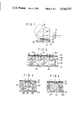
- FIG. 2 is a fragmentary sectional view showing, in an enlarged scale, an information display member which is one embodiment of the present invention
- FIGS. 3 and 4 are fragmentary sectional views respectively showing, in the same enlarged scale, information display members which are other embodiments of the present invention.
- FIG. 5 is a plan view illustrating the visual field of a view finder
- FIG. 6 is a schematic view of a further embodiment of the present invention which utilizes the Albada finder.
- FIGS. 7A, 7B and 7C are plan views respectively showing modifications of the light diffusion member.
- FIG. 1 there is shown a finder optical system in a single-lens reflex camera.
- An imaging beam passed through a camera lens is reflected by a swingable mirror (not shown) toward a focus plate 11 whereat an object is imaged.
- the image can be observed through a pentagonal-roof prism 12 and an eyepiece 13.
- An information display member 20 is located between the focus plate 11 and the prism 12 at the peripheral frame area of a finder visual field frame 14. As shown in FIG. 2, the information display member 20 comprises a display film 21 and an illumination unit 22.
- the display film 21 may be a light blocking film having a plurality of light transmitting portions each of which defines a reference character or a light transmitting film having a plurality of light blocking portions.
- the illumination unit 22 comprises a base plate 23 including a plurality of light emission elements 24 such as light emission diodes each of which corresponds to the respective one of plural reference characters 21a on the display film 21, a light blocking plate having partitions 25 disposed between each adjacent light emission element, a light diffusion member 26 located between the light blocking frame and the display film 21, and a condenser lens 27 located in each of frames defined by the partitions 25.
- Each of the condenser lenses 27 is adapted to deflect the light from the respective light emission element 24 to form a substantially collimated light beam which in turn irradiates a light diffusion member 26 in a uniform manner.
- the condenser lens 27 is normally made of a transparent plastic material and is disposed near the backface of the light diffusion member 26 as shown in FIG. 2. If the condenser lens 27 is of plano-convex type, it may be formed integrally with the light diffusion member 26 at the plane face side of the lens. If the convex face of the condenser lens 27 faces the light diffusion member 26, the condenser lens may include a cylindrical portion 128 formed thereon at the side of the base plate 23 as shown by 127 in FIG. 3. The cylindrical portion 128 of the condenser lens 127 is adhered to and supported by the base plate 23. As shown in FIG. 4, furthermore, each of the light emission elements 24 is covered directly by the respective one of the condenser lenses 227. It is preferred that either of the condenser lens 27, 127 or 227 shown in FIGS. 2, 3 or 4 is of aspherical type.
- FIG. 5 shows a visual field formed by the finder optical system.
- a taking field 30 is defined by the visual field frame 14 surrounded by the focus plate 11 of FIG. 1.
- information to be displayed (in this case, aperture value of 5.6) is displayed out of one side of the taking field 30 by a reference character 21a.
- This displayed information is obtained by illuminating that reference character 21a on the display film 21 only by the use of a light emission element 24 corresponding to the information to be displayed.
- the illumination beam Ld passes through the bottom face of the pentagonal-roof prism 12 and is then reflected by the inner side faces of the same prism 12 toward the eyepiece 13 along the optical path as shown by the broken line in FIG. 1.
- the taking field 30 is observed by a person through the eyepiece 13, the reference character 21a also is observed adjacent the side of the taking field 30 as information.
- FIG. 6 shows a camera having Albada finder into which a display system according to the present invention is incorporated.
- Light from an object passes through a negative objective lens 41 and positive eyepiece 42 in the finder.
- the virtual image of the object may be observed through the eyepiece 42.
- light emitted from each of the light emission elements in the information display member 20 located adjacent the Albada finder optical system passes through the condenser lens, light diffusion member and display film 21 and thereafter is incident on the eyepiece 42 through a trapezoidal prism 43 which is located upstream of the eyepiece 42 and out of the optical path for observing the object.
- the display film 21 is located within the range through which the visual field of the person's eye observed through the eyepiece 42 can be adjusted. Therefore, any reference character on the display film can be observed by the person together with the object within the view finder.
- a light emission element 24 for illuminating a reference character 21a on the information display member 20 which corresponds to the determined taking condition will be controlled to emit a light.
- This light from the light emission element 24 is restricted by the partitions 25 with respect to its illuminatable range.
- the light is condensed to form a substantially collimated light beam by the respective condenser lens 27, 127 or 227 which is disposed within the corresponding frame defined by the partitions 25 and then conducted into the light diffusion member 26.
- Most of the beams slantingly emitted from the light emission elements 24 are deflected toward the light diffusion member 26 by means of the respective lenses 27, 127 or 227. Therefore, the amount of light to be projected onto the light diffusion member 26 is increased and made uniform.
- the light diffusion member may be constructed in various different forms.
- the light diffusion member may include a plurality of finely divided quadrangular pyramids, hexagonal pyramids or cones formed thereon at the surface, as shown by 126, 226 or 326 in FIGS. 7A to 7C. These configurations of the light diffusion member have less light diffusion. Even if such configurations of the light diffusion member are used in the apparatus according to the present invention, sufficient light can be transmitted to the eyepiece of the finder so that the information will be displayed uniformly with very increased illuminance. It is also preferred that the side and bottom faces of each of the partitions are coated with metallic film to form mirror surfaces thereon such that the light from each of the light emission elements will more effectively be transmitted forwardly.
Landscapes
- Physics & Mathematics (AREA)
- General Physics & Mathematics (AREA)
- Indication In Cameras, And Counting Of Exposures (AREA)
- Viewfinders (AREA)
Abstract
Description
Claims (5)
Applications Claiming Priority (2)
| Application Number | Priority Date | Filing Date | Title |
|---|---|---|---|
| JP1983033404U JPS59138838U (en) | 1983-03-08 | 1983-03-08 | Camera viewfinder display device |
| JP58-33404[U] | 1983-03-08 |
Publications (1)
| Publication Number | Publication Date |
|---|---|
| US4544252A true US4544252A (en) | 1985-10-01 |
Family
ID=12385654
Family Applications (1)
| Application Number | Title | Priority Date | Filing Date |
|---|---|---|---|
| US06/585,247 Expired - Lifetime US4544252A (en) | 1983-03-08 | 1984-03-01 | Apparatus for displaying information in camera view finder |
Country Status (2)
| Country | Link |
|---|---|
| US (1) | US4544252A (en) |
| JP (1) | JPS59138838U (en) |
Cited By (6)
| Publication number | Priority date | Publication date | Assignee | Title |
|---|---|---|---|---|
| US4727457A (en) * | 1986-01-24 | 1988-02-23 | U.S. Philips Corporation | Surface-mounted optoelectronic device |
| US4958180A (en) * | 1987-05-23 | 1990-09-18 | Minolta Camera Kabushiki Kaisha | Focus detecting device and auxiliary illuminating device therefor |
| US5386260A (en) * | 1990-11-15 | 1995-01-31 | Asahi Kogaku Kogyo Kabushiki Kaisha | Camera having indicator with finder |
| US5628039A (en) * | 1993-05-28 | 1997-05-06 | Fuji Photo Film Co., Ltd. | Lens-fitted photographic film unit |
| US6408138B1 (en) * | 2000-02-24 | 2002-06-18 | Umax Data Systems, Inc. | Camera view-correction apparatus for taking pictures |
| US7663817B1 (en) * | 2007-01-19 | 2010-02-16 | Siimpel Corporation | Optical system with plano convex lens |
Citations (5)
| Publication number | Priority date | Publication date | Assignee | Title |
|---|---|---|---|---|
| DE197705C (en) * | ||||
| US4165167A (en) * | 1977-06-24 | 1979-08-21 | Veb Pentacon Dresden Kamera-Undkinowerke | Photographic camera |
| US4185891A (en) * | 1977-11-30 | 1980-01-29 | Grumman Aerospace Corporation | Laser diode collimation optics |
| US4265522A (en) * | 1976-09-07 | 1981-05-05 | Canon Kabushiki Kaisha | Camera having a holographic indicator |
| JPS57130828A (en) * | 1981-02-05 | 1982-08-13 | Yamaha Motor Co Ltd | Liquid volume detecting device of liquid container |
Family Cites Families (1)
| Publication number | Priority date | Publication date | Assignee | Title |
|---|---|---|---|---|
| JPS5230125B2 (en) * | 1973-08-21 | 1977-08-05 |
-
1983
- 1983-03-08 JP JP1983033404U patent/JPS59138838U/en active Pending
-
1984
- 1984-03-01 US US06/585,247 patent/US4544252A/en not_active Expired - Lifetime
Patent Citations (5)
| Publication number | Priority date | Publication date | Assignee | Title |
|---|---|---|---|---|
| DE197705C (en) * | ||||
| US4265522A (en) * | 1976-09-07 | 1981-05-05 | Canon Kabushiki Kaisha | Camera having a holographic indicator |
| US4165167A (en) * | 1977-06-24 | 1979-08-21 | Veb Pentacon Dresden Kamera-Undkinowerke | Photographic camera |
| US4185891A (en) * | 1977-11-30 | 1980-01-29 | Grumman Aerospace Corporation | Laser diode collimation optics |
| JPS57130828A (en) * | 1981-02-05 | 1982-08-13 | Yamaha Motor Co Ltd | Liquid volume detecting device of liquid container |
Cited By (6)
| Publication number | Priority date | Publication date | Assignee | Title |
|---|---|---|---|---|
| US4727457A (en) * | 1986-01-24 | 1988-02-23 | U.S. Philips Corporation | Surface-mounted optoelectronic device |
| US4958180A (en) * | 1987-05-23 | 1990-09-18 | Minolta Camera Kabushiki Kaisha | Focus detecting device and auxiliary illuminating device therefor |
| US5386260A (en) * | 1990-11-15 | 1995-01-31 | Asahi Kogaku Kogyo Kabushiki Kaisha | Camera having indicator with finder |
| US5628039A (en) * | 1993-05-28 | 1997-05-06 | Fuji Photo Film Co., Ltd. | Lens-fitted photographic film unit |
| US6408138B1 (en) * | 2000-02-24 | 2002-06-18 | Umax Data Systems, Inc. | Camera view-correction apparatus for taking pictures |
| US7663817B1 (en) * | 2007-01-19 | 2010-02-16 | Siimpel Corporation | Optical system with plano convex lens |
Also Published As
| Publication number | Publication date |
|---|---|
| JPS59138838U (en) | 1984-09-17 |
Similar Documents
| Publication | Publication Date | Title |
|---|---|---|
| US4367463A (en) | Information mark display device | |
| US5473403A (en) | Camera having a multi-point focus detecting device | |
| US6292629B1 (en) | Indicator provided within finder for single lens reflex camera | |
| US5053803A (en) | Information display apparatus for camera | |
| US4268143A (en) | Photographic camera with provision for recording supplemental data | |
| US5519466A (en) | Electronically controlled camera | |
| US4544252A (en) | Apparatus for displaying information in camera view finder | |
| US4907026A (en) | Light projection system for automatic focus detection | |
| US4200380A (en) | Camera provided with means for giving information about photographing | |
| JP2696911B2 (en) | Display observation device | |
| JPH0251114A (en) | Auxiliary irradiation device for focus detection | |
| JP2749829B2 (en) | Single-lens reflex camera body to display in viewfinder | |
| US5850578A (en) | Light-projecting system for automatic focus detection | |
| US5119124A (en) | Camera with finder of clear display | |
| US4527875A (en) | Illuminated finder | |
| GB1566833A (en) | Replaceable finder system for singlelens reflex camera | |
| US4171896A (en) | Photographic camera with an information indicating finder | |
| JP2503519Y2 (en) | Information display device | |
| US5913087A (en) | Indicating apparatus within viewfinder of single lens reflex camera | |
| JP2002055384A (en) | Finder device and camera using the same | |
| US5426483A (en) | Camera with a line of sight detecting device | |
| JPH03192340A (en) | Indication device within finder for single-lens reflex camera | |
| JPH04278931A (en) | Display observation device | |
| US5475458A (en) | Albada finder | |
| US20100027985A1 (en) | In-finder display apparatus |
Legal Events
| Date | Code | Title | Description |
|---|---|---|---|
| AS | Assignment |
Owner name: NIPPON KOGAKU K.K., 2-3, MARUNOUCHI 3-CHOME, CHIYO Free format text: ASSIGNMENT OF ASSIGNORS INTEREST.;ASSIGNOR:TSUKAMOTO, MASAAKI;REEL/FRAME:004238/0873 Effective date: 19840228 |
|
| STCF | Information on status: patent grant |
Free format text: PATENTED CASE |
|
| FEPP | Fee payment procedure |
Free format text: PAYOR NUMBER ASSIGNED (ORIGINAL EVENT CODE: ASPN); ENTITY STATUS OF PATENT OWNER: LARGE ENTITY |
|
| AS | Assignment |
Owner name: NIKON CORPORATION, 2-3, MARUNOUCHI 3-CHOME, CHIYOD Free format text: CHANGE OF NAME;ASSIGNOR:NIPPON KOGAKU, K.K.;REEL/FRAME:004935/0584 |
|
| FPAY | Fee payment |
Year of fee payment: 4 |
|
| FEPP | Fee payment procedure |
Free format text: PAYER NUMBER DE-ASSIGNED (ORIGINAL EVENT CODE: RMPN); ENTITY STATUS OF PATENT OWNER: LARGE ENTITY Free format text: PAYOR NUMBER ASSIGNED (ORIGINAL EVENT CODE: ASPN); ENTITY STATUS OF PATENT OWNER: LARGE ENTITY |
|
| FEPP | Fee payment procedure |
Free format text: PAYER NUMBER DE-ASSIGNED (ORIGINAL EVENT CODE: RMPN); ENTITY STATUS OF PATENT OWNER: LARGE ENTITY Free format text: PAYOR NUMBER ASSIGNED (ORIGINAL EVENT CODE: ASPN); ENTITY STATUS OF PATENT OWNER: LARGE ENTITY |
|
| FPAY | Fee payment |
Year of fee payment: 8 |
|
| FPAY | Fee payment |
Year of fee payment: 12 |