US4542952A - Electrical connector assembly having locking means - Google Patents
Electrical connector assembly having locking means Download PDFInfo
- Publication number
- US4542952A US4542952A US06/604,796 US60479684A US4542952A US 4542952 A US4542952 A US 4542952A US 60479684 A US60479684 A US 60479684A US 4542952 A US4542952 A US 4542952A
- Authority
- US
- United States
- Prior art keywords
- pin
- detent
- plate
- disposed
- extending
- Prior art date
- Legal status (The legal status is an assumption and is not a legal conclusion. Google has not performed a legal analysis and makes no representation as to the accuracy of the status listed.)
- Expired - Fee Related
Links
- 230000008878 coupling Effects 0.000 claims abstract description 47
- 238000010168 coupling process Methods 0.000 claims abstract description 47
- 238000005859 coupling reaction Methods 0.000 claims abstract description 47
- 230000001154 acute effect Effects 0.000 claims description 8
- 230000003213 activating effect Effects 0.000 claims 1
- 239000002184 metal Substances 0.000 abstract description 17
- 230000013011 mating Effects 0.000 description 3
- 238000013459 approach Methods 0.000 description 2
- 239000003989 dielectric material Substances 0.000 description 2
- 238000000926 separation method Methods 0.000 description 2
Images

Classifications
-
- H—ELECTRICITY
- H01—ELECTRIC ELEMENTS
- H01R—ELECTRICALLY-CONDUCTIVE CONNECTIONS; STRUCTURAL ASSOCIATIONS OF A PLURALITY OF MUTUALLY-INSULATED ELECTRICAL CONNECTING ELEMENTS; COUPLING DEVICES; CURRENT COLLECTORS
- H01R13/00—Details of coupling devices of the kinds covered by groups H01R12/70 or H01R24/00 - H01R33/00
- H01R13/62—Means for facilitating engagement or disengagement of coupling parts or for holding them in engagement
- H01R13/625—Casing or ring with bayonet engagement
-
- H—ELECTRICITY
- H01—ELECTRIC ELEMENTS
- H01R—ELECTRICALLY-CONDUCTIVE CONNECTIONS; STRUCTURAL ASSOCIATIONS OF A PLURALITY OF MUTUALLY-INSULATED ELECTRICAL CONNECTING ELEMENTS; COUPLING DEVICES; CURRENT COLLECTORS
- H01R13/00—Details of coupling devices of the kinds covered by groups H01R12/70 or H01R24/00 - H01R33/00
- H01R13/62—Means for facilitating engagement or disengagement of coupling parts or for holding them in engagement
- H01R13/623—Casing or ring with helicoidal groove
Definitions
- This invention relates to an electrical connector assembly having locking means.
- An electrical connector assembly includes a rotatably mounted coupling member to assemble and retain plug and receptacle connector members together in mated relation and a locking arrangement operative with the coupling member to prevent unwanted separation of the connector members after mating has been achieved.
- One locking arrangement comprises a bayonet connection wherein a force generated by a compressed wave washer causes bayonet pins from the receptacle to work against grooves on the coupling member and to seat in a detent disposed at the end of the groove, the biased seating preventing unwanted rotation of the coupling member and indicating that a fully mated condition has been reached.
- metal-to-metal contact between the mated connector members is absolutely essential for proper operation of the connector. Because of the cooperation of the wave washer and action of the bayonet pin against the groove, excessive wear is known to occur. Such wear could cause the detents to become shallow and compromise metal-to-metal contact.
- a one-piece C-ring includes three "U-shaped” bumps for positioning the C-ring against an end wall of the coupling nut and three "V-shaped" risers spaced 120° apart for opposing the reverse movement of the bayonet pins.
- Such a C-ring may be undesirable because the 120° spacing of the risers may not be accurately maintained.
- the bayonet pin works against the sidewall of a bayonet groove adjacent to the riser and must deflect the riser to be captivated.
- the axial separation of the side wall relative to the end wall varies.
- a locking ring includes a row of detents defined by a succession of peaks and valleys, each detent being adapted to captivate a bayonet pin driven thereacross.
- the user in some applications, may not know if the last detent--indicative of metal-to-metal contact was reached. While such a design has been suitable for the purposes intended, a single detent would provide a single audible click to indicate full mate and may be more desirable by the user in the field.
- a general object of this invention is to provide improved locking means for preventing unwanted rotation of a coupling member relative to mated electrical connector members and maintaining metal-to-metal contact between the connector members when mated.
- a separable electrical connector assembly comprises mating plug and receptacle connector members, a coupling member rotatably mounted to the plug and having a helical groove adapted to engage with a bayonet pin extending from the receptacle to draw the plug and receptacle connector members together into mated relation wherein the connector members are in metal-to-metal contact, and locking means for preventing unwanted rotation of the coupling member and maintaining metal-to-metal contact after the connector members are in mated relation.
- the locking means is characterized by a spring member disposed at the terminus of the helical groove for captivating the bayonet pin when the pin is rotated thereto, the spring member comprising a plate for mounting the spring member to the coupling member and a resilient element provided with a detent for captivating the bayonet pin when the coupling member has advanced the connector members to the predetermined metal contacting position.
- the resilient element intercepts the helical groove and comprises an elongated leaf member formed into a U-shaped section which extends perpendicularly from the plate with the leaf member having one end of the "U” secured to the plate and the other end of the "U” cantilevered therefrom and disposed in the groove to be deflected rearwardly upon engagement with the bayonet pin whereupon the detent captivates the pin to prevent unwanted uncoupling rotation of the coupling member.
- annular rib is disposed around the interior wall of the coupling member, the rib including a gap which intersects the terminus of the groove and receives the plate.
- the cantilevered other end of the leaf includes a resilient foot, the foot being adapted to abut the rib and bias the leaf with its detent forwardly to enhance the pin captivation.
- An advantage of this invention is provision of a simple locking spring which does not induce wear on the pin captivating pocket of a bayonet groove which would then frustrate axial metal-to-metal engagement between the connector members, and which provides an audible "click" to indicate to a user that a positive metal-to-metal locked engagement between the connector members has been achieved.
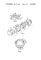
- FIG. 1 is an exploded view of an electrical connector assembly.
- FIG. 2 is a spring member having a detent.
- FIG. 3 is the electrical connector assembly of FIG. 1 when mated with portions thereof being cut-away and partially in section.
- FIG. 4 is a partial side view, in section, of the mated electrical connector assembly.
- FIG. 5 is a cross-section view of the mated electrical connector assembly taken along lines V--V of FIG. 3.
- FIG. 1 shows a separable electrical connector assembly comprising a pair of connector members adapted for a quick connection by a coupling nut utilizing a bayonet-type coupling arrangement for drawing the connector members together, the coupling arrangement releasably locking the connector members together in metal-to-metal engagement.
- the connector assembly comprises a receptacle connector 10 having an axial keyway 14, a plug connector 20 having a key 24, a coupling nut 30 adapted to be rotatably carried about plug connector 20 for connecting with receptacle connector 10, a retaining ring 50 for captivating the coupling nut to the plug connector, a waved washer 52, and a spring member 40 for locking the connectors together, the key 24 being adapted to be received by the keyway 14 for orienting the plug connector relative to the receptacle connector and constraining the plug to be drawn axially into the receptacle upon rotation of coupling nut 30.
- Receptacle connector 10 comprises a generally cylindrical metal shell 12 having an end face 16 and three radially extending bayonet pins 18, the pins being adjacent end face 16 and spaced equiangularly about the outer surface of shell 12.
- An insert 19 of dielectric material is mounted in the shell, the insert carrying a plurality of pin-type contacts 17 therein.
- Plug connector 20 comprises a generally cylindrical metal shell 22 including an annular flange 28 and an annular recess 27 circumjacent to the flange, the flange 28 extending radially outward from shell 22 and having a forward face 26 which is adapted to abut end face 16 of the receptacle shell when the connectors are mated.
- An insert 29 of dielectric material is mounted in the plug, the insert 29 carrying a plurality of socket-type contacts (not shown) which are adapted to be connected separately with corresponding of the associated pin-type contacts.
- the contacts could be other than shown and described.
- the coupling nut 30 comprises a cylindrical sleeve 32 having a front face 33 and a radial flange 34 extending radially inward from a rearward portion of the sleeve, the radial flange being adapted to clearance fit about annular recess 27 of the plug shell for rotation thereabout and cylindrical sleeve 32 being adapted to telescope about receptacle shell 12.
- Sleeve 32 includes three helical grooves 36 on its internal wall to connect with one of the respective bayonet pins 18, each groove opening on front face 33 and extending helically inward therefrom to an interior terminus 35.
- Each spring member 40 is adapted to be carried by the coupling nut, each spring member being configured so as to be seated at the terminus 35 of each bayonet groove and each including a resilient, U-shaped, leaf member 44 having a locking detent 46, the detent captivating its associated bayonet pin 18 received therein to prevent unwanted reverse rotation of the coupling nut.
- FIG. 2 shows spring member 40 as being one-piece and comprising a slightly arcuate base plate 42 having a tab 41 extending therefrom and the U-shaped leaf member 44 extending substantially perpendicularly to base plate 42 and tab 41.
- the leaf member folds an elongated leaf about and into a "U" section to describe spaced upper and lower leaf portions 45, 47, the lower leaf portion 47 rigidly interconnecting leaf member 44 to base plate 42 and the upper leaf portion 45 defining a cantilever-type beam having a deflectable end 45a and including the detent 46, the upper leaf portion being resiliently yieldable towards the lower leaf portion and terminating in a foot portion 43 inclined at an acute angle thereto downwardly therefrom towards lower leaf portion 47.
- Base plate 42 conforms to the inner wall of the coupling nut and has top and bottom edges 42a, 42b, lateral edges 42c, 42d, an aperture 42e sized to receive a pin or a rivet to secure the plate to the coupling nut, and the tab 41, the tab having lateral end faces 41a, 41 b and securing the lower leaf portion 47 to the top edge of the plate.
- the tab and the plate in combination, cooperate to define a pair of notches and a pair of laterally extending plate portions for seating the spring member in a gap on the coupling nut.
- Detent 46 includes a flank 46a for abutting pin 18, the flank being disposed at an acute angle relative to a vertical line from upper leaf portion 45 and shown by 48.
- acute angle 48 As acute angle 48 approaches zero degrees (i.e., flank 46a is perpendicular to the leaf portion) the greater is the resistance to uncoupling rotation. Conversely, as acute angle 48 approaches 90° (i.e., flank 46a is level with the leaf portion) the more likely that rotation may be permitted. Preferably, acute angle 48 would be in the range of between 20°-40°.
- FIG. 3 shows plug 20, receptacle 10 and coupling nut 30 in mated relation, and pin 18 from receptacle shell 12 captivated in detent 46.
- the inner wall of coupling sleeve 32 is provided with an annular rib 60 axially forward of radial flange 34, the annular rib having a forward wall 62 which is facing terminus 35 of the helical groove 36 and a rearward wall 64 which is facing annular flange 28, an annular groove 66 being defined between the annular rib 60 and radial flange 34.
- Annular rib 60 includes an arcuate gap defined by angularly spaced sidewalls 60a, 60b.
- Spring member 40 is mounted to the inner wall of coupling sleeve 32 such that U-shaped leaf member 44 and tab 41 seat between the arcuate gap with end faces 41a, 41b abutting the respective spaced sidewalls 60a, 60b, the plate has its plate portions 42 extending laterally and seating in annular groove 66 with top and bottom edges 42a, 42b thereof abutting, respectively, the rearward wall 64 of annular rib 60 and radial flange 34, the pin 18 being captivated in detent 46 and abutted against flank 46a, and the foot portion 43 of upper leaf portion 45 biased against the forward wall 62 of annular rib 60.
- a pin 70 passes through aperture 42e to rigidly secure spring member 40 to coupling nut 30.
- FIG. 4 shows a side view of the mated relation between plug and receptacle shells 12, 22 wherein the forward face 26 of the plug is disposed in metal-to-metal contact with end face 16 of the receptacle.
- Spring member 40 carried on coupling sleeve 32, is disposed in annular groove 66 formed between radial flange 34 and rib 60.
- Bayonet pin 18 is captivated by detent 46.
- FIG. 5 shows a cross-section of the mated connector assembly with three bayonet pins 18 being captivated within the respective detents 46 in each of three equiangularly disposed spring members 40.
- a set of three like arcuate gaps are disposed in annular rib 60, each gap being defined by angularly spaced sidewalls 60a, 60b and each registered with the terminus of one helical groove 36.
Landscapes
- Details Of Connecting Devices For Male And Female Coupling (AREA)
Abstract
Description
Claims (11)
Priority Applications (3)
| Application Number | Priority Date | Filing Date | Title |
|---|---|---|---|
| US06/604,796 US4542952A (en) | 1984-04-27 | 1984-04-27 | Electrical connector assembly having locking means |
| EP85104045A EP0163064A3 (en) | 1984-04-27 | 1985-04-03 | Electrical connector assembly having locking means |
| CA000480072A CA1227842A (en) | 1984-04-27 | 1985-04-25 | Electrical connector assembly having locking means |
Applications Claiming Priority (1)
| Application Number | Priority Date | Filing Date | Title |
|---|---|---|---|
| US06/604,796 US4542952A (en) | 1984-04-27 | 1984-04-27 | Electrical connector assembly having locking means |
Publications (1)
| Publication Number | Publication Date |
|---|---|
| US4542952A true US4542952A (en) | 1985-09-24 |
Family
ID=24421093
Family Applications (1)
| Application Number | Title | Priority Date | Filing Date |
|---|---|---|---|
| US06/604,796 Expired - Fee Related US4542952A (en) | 1984-04-27 | 1984-04-27 | Electrical connector assembly having locking means |
Country Status (3)
| Country | Link |
|---|---|
| US (1) | US4542952A (en) |
| EP (1) | EP0163064A3 (en) |
| CA (1) | CA1227842A (en) |
Cited By (20)
| Publication number | Priority date | Publication date | Assignee | Title |
|---|---|---|---|---|
| US5145394A (en) * | 1991-10-03 | 1992-09-08 | G & H Technology, Inc. | Anti-rotation assembly for interconnect devices |
| EP0580468A1 (en) * | 1992-07-24 | 1994-01-26 | Framatome Connectors International | Connection assembly with bayonet-type locking |
| US5786976A (en) * | 1996-07-16 | 1998-07-28 | Hydraflow | Coupling with hard metallic ductile conductive coating |
| US5800197A (en) * | 1996-10-18 | 1998-09-01 | Itt Manufacturing Enterprises, Inc. | Connector system with quick coupling/decoupling |
| US5959828A (en) * | 1996-07-16 | 1999-09-28 | Hydraflow | Coupling with insulated flanges |
| US5960819A (en) * | 1996-08-07 | 1999-10-05 | Borg-Warner Automotive, Inc. | Valve having multi-part valve housing |
| US6039594A (en) * | 1997-12-03 | 2000-03-21 | Palazzoli S.P.A. | Body for electrical outlet or plug |
| US20070093109A1 (en) * | 2005-10-20 | 2007-04-26 | Emmanuel Czarnyszka | Connector for a contact element |
| US20110113592A1 (en) * | 2008-07-31 | 2011-05-19 | Mtd Products Inc. | Blower/vacuum tube attachment |
| US20120256411A1 (en) * | 2011-04-08 | 2012-10-11 | Yu-Yi Chien | Connector Assembly |
| US8579659B2 (en) | 2012-03-13 | 2013-11-12 | Carlisle Interconnect Technologies, Inc. | SMP electrical connector and connector system |
| CN106549261A (en) * | 2016-10-20 | 2017-03-29 | 郭睿航 | A socket, a plug, a charging connection system, and a charging pile with the system |
| DE112014003125B4 (en) | 2013-07-02 | 2018-05-30 | Yazaki Corporation | rotary connector |
| WO2019030035A1 (en) * | 2017-08-08 | 2019-02-14 | Phoenix Contact Gmbh & Co. Kg | CONNECTOR COMPONENT WITH A LOCKING ELEMENT |
| US11248638B2 (en) * | 2016-11-01 | 2022-02-15 | Lucian IVAN | Pole section for assembly into a pole for cleaning elevated windows and/or gutters |
| US20220302643A1 (en) * | 2021-03-19 | 2022-09-22 | Tyco Electronics (Shanghai) Co. Ltd. | Connector and Connector Assembly |
| US12107366B2 (en) | 2021-03-19 | 2024-10-01 | Tyco Electronics (Shanghai) Co. Ltd. | Connector and connector assembly |
| US12170425B2 (en) | 2021-03-19 | 2024-12-17 | Tyco Electronics (Shanghai) Co., Ltd. | Connector and connector assembly |
| US12224528B2 (en) | 2021-03-19 | 2025-02-11 | Tyco Electronics (Shanghai) Co. Ltd. | Connector and connector assembly |
| US12592506B2 (en) | 2023-04-12 | 2026-03-31 | Amphenol Cable And Interconnect Technologies, Inc. | Electrical connector assembly with snap locking features |
Citations (23)
| Publication number | Priority date | Publication date | Assignee | Title |
|---|---|---|---|---|
| US1871421A (en) * | 1928-12-07 | 1932-08-09 | Adams Grease Gun Corp | High pressure coupler |
| US3351886A (en) * | 1965-12-14 | 1967-11-07 | Amp Inc | Electrical connector having improved coupling means |
| US3455580A (en) * | 1967-04-07 | 1969-07-15 | Pyle National Co | Locking device in bayonet electrical connector |
| US3594700A (en) * | 1969-08-20 | 1971-07-20 | Pyle National Co | Electrical connector with threaded coupling nut lock |
| US3601764A (en) * | 1969-01-28 | 1971-08-24 | Bunker Ramo | Lock device for coupling means |
| US3665371A (en) * | 1969-05-19 | 1972-05-23 | Bunker Ramo | Electrical connectors |
| US3808580A (en) * | 1972-12-18 | 1974-04-30 | Matrix Science Corp | Self-locking coupling nut for electrical connectors |
| US3840839A (en) * | 1973-02-01 | 1974-10-08 | Akzona Inc | Asymmetrical electrical connector with aligning means |
| US3901574A (en) * | 1971-12-30 | 1975-08-26 | Amp Inc | Electrical connector |
| US3917373A (en) * | 1974-06-05 | 1975-11-04 | Bunker Ramo | Coupling ring assembly |
| US3947081A (en) * | 1974-11-11 | 1976-03-30 | International Telephone & Telegraph Corporation | Low insertion force circular electrical connector |
| US3971614A (en) * | 1972-11-03 | 1976-07-27 | Akzona Incorporated | Electrical connector with means for maintaining a connected condition |
| US4007953A (en) * | 1975-09-10 | 1977-02-15 | International Telephone And Telegraph Corporation | Removable captive coupling nut assembly |
| US4023881A (en) * | 1975-09-12 | 1977-05-17 | Souriau Et Cie | Connectors |
| US4059324A (en) * | 1976-09-15 | 1977-11-22 | The Bendix Corporation | Electrical connector |
| US4165910A (en) * | 1977-10-25 | 1979-08-28 | Bunker Ramo Corporation | Electrical connector |
| US4204740A (en) * | 1974-03-22 | 1980-05-27 | Bunker Ramo Corporation | Connector coupling ring retainer apparatus and electrical connector assembly retaining means |
| US4235498A (en) * | 1979-07-26 | 1980-11-25 | The Bendix Corporation | Electrical connector with locking means |
| US4239315A (en) * | 1978-12-18 | 1980-12-16 | International Telephone And Telegraph Corporation | Electrical connector |
| US4290662A (en) * | 1979-07-11 | 1981-09-22 | Bunker Ramo Corporation | Connector assembly with visual, tactile and audible indication |
| US4305180A (en) * | 1979-12-14 | 1981-12-15 | International Telephone And Telegraph Corporation | Bayonet coupling nut |
| US4359256A (en) * | 1980-11-14 | 1982-11-16 | The Bendix Corporation | Electrical connector coupling member |
| US4464001A (en) * | 1982-09-30 | 1984-08-07 | The Bendix Corporation | Coupling nut having an anti-decoupling device |
Family Cites Families (1)
| Publication number | Priority date | Publication date | Assignee | Title |
|---|---|---|---|---|
| US3892458A (en) * | 1973-04-04 | 1975-07-01 | Deutsch Co Elec Comp | Coupling for electrical connector or the like |
-
1984
- 1984-04-27 US US06/604,796 patent/US4542952A/en not_active Expired - Fee Related
-
1985
- 1985-04-03 EP EP85104045A patent/EP0163064A3/en not_active Withdrawn
- 1985-04-25 CA CA000480072A patent/CA1227842A/en not_active Expired
Patent Citations (23)
| Publication number | Priority date | Publication date | Assignee | Title |
|---|---|---|---|---|
| US1871421A (en) * | 1928-12-07 | 1932-08-09 | Adams Grease Gun Corp | High pressure coupler |
| US3351886A (en) * | 1965-12-14 | 1967-11-07 | Amp Inc | Electrical connector having improved coupling means |
| US3455580A (en) * | 1967-04-07 | 1969-07-15 | Pyle National Co | Locking device in bayonet electrical connector |
| US3601764A (en) * | 1969-01-28 | 1971-08-24 | Bunker Ramo | Lock device for coupling means |
| US3665371A (en) * | 1969-05-19 | 1972-05-23 | Bunker Ramo | Electrical connectors |
| US3594700A (en) * | 1969-08-20 | 1971-07-20 | Pyle National Co | Electrical connector with threaded coupling nut lock |
| US3901574A (en) * | 1971-12-30 | 1975-08-26 | Amp Inc | Electrical connector |
| US3971614A (en) * | 1972-11-03 | 1976-07-27 | Akzona Incorporated | Electrical connector with means for maintaining a connected condition |
| US3808580A (en) * | 1972-12-18 | 1974-04-30 | Matrix Science Corp | Self-locking coupling nut for electrical connectors |
| US3840839A (en) * | 1973-02-01 | 1974-10-08 | Akzona Inc | Asymmetrical electrical connector with aligning means |
| US4204740A (en) * | 1974-03-22 | 1980-05-27 | Bunker Ramo Corporation | Connector coupling ring retainer apparatus and electrical connector assembly retaining means |
| US3917373A (en) * | 1974-06-05 | 1975-11-04 | Bunker Ramo | Coupling ring assembly |
| US3947081A (en) * | 1974-11-11 | 1976-03-30 | International Telephone & Telegraph Corporation | Low insertion force circular electrical connector |
| US4007953A (en) * | 1975-09-10 | 1977-02-15 | International Telephone And Telegraph Corporation | Removable captive coupling nut assembly |
| US4023881A (en) * | 1975-09-12 | 1977-05-17 | Souriau Et Cie | Connectors |
| US4059324A (en) * | 1976-09-15 | 1977-11-22 | The Bendix Corporation | Electrical connector |
| US4165910A (en) * | 1977-10-25 | 1979-08-28 | Bunker Ramo Corporation | Electrical connector |
| US4239315A (en) * | 1978-12-18 | 1980-12-16 | International Telephone And Telegraph Corporation | Electrical connector |
| US4290662A (en) * | 1979-07-11 | 1981-09-22 | Bunker Ramo Corporation | Connector assembly with visual, tactile and audible indication |
| US4235498A (en) * | 1979-07-26 | 1980-11-25 | The Bendix Corporation | Electrical connector with locking means |
| US4305180A (en) * | 1979-12-14 | 1981-12-15 | International Telephone And Telegraph Corporation | Bayonet coupling nut |
| US4359256A (en) * | 1980-11-14 | 1982-11-16 | The Bendix Corporation | Electrical connector coupling member |
| US4464001A (en) * | 1982-09-30 | 1984-08-07 | The Bendix Corporation | Coupling nut having an anti-decoupling device |
Cited By (29)
| Publication number | Priority date | Publication date | Assignee | Title |
|---|---|---|---|---|
| US5145394A (en) * | 1991-10-03 | 1992-09-08 | G & H Technology, Inc. | Anti-rotation assembly for interconnect devices |
| EP0580468A1 (en) * | 1992-07-24 | 1994-01-26 | Framatome Connectors International | Connection assembly with bayonet-type locking |
| FR2694053A1 (en) * | 1992-07-24 | 1994-01-28 | Souriau & Cie | Bayonet type locking connection assembly. |
| US5959828A (en) * | 1996-07-16 | 1999-09-28 | Hydraflow | Coupling with insulated flanges |
| US5786976A (en) * | 1996-07-16 | 1998-07-28 | Hydraflow | Coupling with hard metallic ductile conductive coating |
| US5960819A (en) * | 1996-08-07 | 1999-10-05 | Borg-Warner Automotive, Inc. | Valve having multi-part valve housing |
| US5800197A (en) * | 1996-10-18 | 1998-09-01 | Itt Manufacturing Enterprises, Inc. | Connector system with quick coupling/decoupling |
| US6039594A (en) * | 1997-12-03 | 2000-03-21 | Palazzoli S.P.A. | Body for electrical outlet or plug |
| US20070093109A1 (en) * | 2005-10-20 | 2007-04-26 | Emmanuel Czarnyszka | Connector for a contact element |
| US7479023B2 (en) * | 2005-10-20 | 2009-01-20 | Souriau | Connector for a contact element |
| US20110113592A1 (en) * | 2008-07-31 | 2011-05-19 | Mtd Products Inc. | Blower/vacuum tube attachment |
| US20120256411A1 (en) * | 2011-04-08 | 2012-10-11 | Yu-Yi Chien | Connector Assembly |
| US8646812B2 (en) * | 2011-04-08 | 2014-02-11 | Apex Medical Corp. | Connector assembly |
| US8579659B2 (en) | 2012-03-13 | 2013-11-12 | Carlisle Interconnect Technologies, Inc. | SMP electrical connector and connector system |
| DE112014003125B4 (en) | 2013-07-02 | 2018-05-30 | Yazaki Corporation | rotary connector |
| CN106549261A (en) * | 2016-10-20 | 2017-03-29 | 郭睿航 | A socket, a plug, a charging connection system, and a charging pile with the system |
| CN106549261B (en) * | 2016-10-20 | 2018-10-30 | 慈溪宏一电子有限公司 | A socket, a plug, a charging connection system, and a charging pile with the system |
| US11248638B2 (en) * | 2016-11-01 | 2022-02-15 | Lucian IVAN | Pole section for assembly into a pole for cleaning elevated windows and/or gutters |
| JP2020530189A (en) * | 2017-08-08 | 2020-10-15 | フェニックス コンタクト ゲーエムベーハー ウント コムパニー カーゲー | Electrical connector parts with locking elements |
| CN110998984A (en) * | 2017-08-08 | 2020-04-10 | 菲尼克斯电气公司 | Plug connector parts with locking element |
| US11081838B2 (en) * | 2017-08-08 | 2021-08-03 | Phoenix Contact Gmbh & Co. Kg | Electrical connector part having a locking element |
| CN110998984B (en) * | 2017-08-08 | 2021-10-26 | 菲尼克斯电气公司 | Plug connector part with locking element |
| WO2019030035A1 (en) * | 2017-08-08 | 2019-02-14 | Phoenix Contact Gmbh & Co. Kg | CONNECTOR COMPONENT WITH A LOCKING ELEMENT |
| US20220302643A1 (en) * | 2021-03-19 | 2022-09-22 | Tyco Electronics (Shanghai) Co. Ltd. | Connector and Connector Assembly |
| US12107366B2 (en) | 2021-03-19 | 2024-10-01 | Tyco Electronics (Shanghai) Co. Ltd. | Connector and connector assembly |
| US12170425B2 (en) | 2021-03-19 | 2024-12-17 | Tyco Electronics (Shanghai) Co., Ltd. | Connector and connector assembly |
| US12224528B2 (en) | 2021-03-19 | 2025-02-11 | Tyco Electronics (Shanghai) Co. Ltd. | Connector and connector assembly |
| US12224524B2 (en) * | 2021-03-19 | 2025-02-11 | Tyco Electronics (Shanghai) Co. Ltd. | Connector assembly with plug, having locking features which are operatively arranged between plug housing and socket housing and are adapted to release portion of insertion path of plug housing and socket housing in rotational position |
| US12592506B2 (en) | 2023-04-12 | 2026-03-31 | Amphenol Cable And Interconnect Technologies, Inc. | Electrical connector assembly with snap locking features |
Also Published As
| Publication number | Publication date |
|---|---|
| EP0163064A3 (en) | 1988-08-31 |
| EP0163064A2 (en) | 1985-12-04 |
| CA1227842A (en) | 1987-10-06 |
Similar Documents
| Publication | Publication Date | Title |
|---|---|---|
| US4542952A (en) | Electrical connector assembly having locking means | |
| US4464001A (en) | Coupling nut having an anti-decoupling device | |
| US4349241A (en) | Electrical connector assembly having enhanced EMI shielding | |
| US4106839A (en) | Electrical connector and frequency shielding means therefor and method of making same | |
| US4066315A (en) | Electrical connector with arcuate detent means | |
| US4478473A (en) | Coupling nut for an electrical connector | |
| US4497530A (en) | Electrical connector having a coupling indicator | |
| USRE31995E (en) | Enhanced detent guide track with dog-leg | |
| EP0023771B1 (en) | Enhanced detent guide track with dog-leg | |
| US4183605A (en) | Electrical connector with arcuate detent means | |
| CA1151258A (en) | Electrical connector coupling ring having an integral spring | |
| US4290662A (en) | Connector assembly with visual, tactile and audible indication | |
| US3901574A (en) | Electrical connector | |
| US3808580A (en) | Self-locking coupling nut for electrical connectors | |
| US4074927A (en) | Electrical connector with insert member retaining means | |
| US5067909A (en) | Locking multiple conductor electrical connector | |
| US4531802A (en) | Electrical connector assembly having locking means | |
| US3892458A (en) | Coupling for electrical connector or the like | |
| US5993266A (en) | Keying system for electrical connector | |
| EP0893852A2 (en) | Connector with releasable mounting flange | |
| GB2056193A (en) | Separable electrical connector with locking means | |
| US4531801A (en) | Plug and receptacle connector locking means | |
| EP0234351A1 (en) | Anti-decoupling resisting and emi shielding means for an electrical connector assembly | |
| US4478474A (en) | Coupling nut for an electrical connector | |
| US4521066A (en) | Electrical connector with non-precockable coupling ring |
Legal Events
| Date | Code | Title | Description |
|---|---|---|---|
| AS | Assignment |
Owner name: ALLIED CORPORATION, COLUMBIA RD & PARK AVE., MORRI Free format text: ASSIGNMENT OF ASSIGNORS INTEREST.;ASSIGNOR:TOMSA, VLADIMIR;REEL/FRAME:004256/0257 Effective date: 19831204 |
|
| FEPP | Fee payment procedure |
Free format text: PAYOR NUMBER ASSIGNED (ORIGINAL EVENT CODE: ASPN); ENTITY STATUS OF PATENT OWNER: LARGE ENTITY |
|
| AS | Assignment |
Owner name: CANADIAN IMPERIAL BANK OF COMMERCE, NEW YORK AGENC Free format text: SECURITY INTEREST;ASSIGNOR:AMPHENOL CORPORATION;REEL/FRAME:004879/0030 Effective date: 19870515 |
|
| AS | Assignment |
Owner name: AMPHENOL CORPORATION, LISLE, ILLINOIS A CORP. OF D Free format text: ASSIGNMENT OF ASSIGNORS INTEREST.;ASSIGNOR:ALLIED CORPORATION, A CORP. OF NY;REEL/FRAME:004844/0850 Effective date: 19870602 Owner name: AMPHENOL CORPORATION, A CORP. OF DE, ILLINOIS Free format text: ASSIGNMENT OF ASSIGNORS INTEREST;ASSIGNOR:ALLIED CORPORATION, A CORP. OF NY;REEL/FRAME:004844/0850 Effective date: 19870602 |
|
| REMI | Maintenance fee reminder mailed | ||
| LAPS | Lapse for failure to pay maintenance fees | ||
| STCH | Information on status: patent discontinuation |
Free format text: PATENT EXPIRED DUE TO NONPAYMENT OF MAINTENANCE FEES UNDER 37 CFR 1.362 |
|
| FP | Lapsed due to failure to pay maintenance fee |
Effective date: 19890924 |
|
| AS | Assignment |
Owner name: AMPHENOL CORPORATION A CORP. OF DELAWARE Free format text: RELEASED BY SECURED PARTY;ASSIGNOR:CANADIAN IMPERIAL BANK OF COMMERCE;REEL/FRAME:006147/0887 Effective date: 19911114 |