US4541681A - Electrical connection of wire conductor(s) to a terminal pin in an electrode assembly of a pacing lead - Google Patents
Electrical connection of wire conductor(s) to a terminal pin in an electrode assembly of a pacing lead Download PDFInfo
- Publication number
- US4541681A US4541681A US06/491,401 US49140183A US4541681A US 4541681 A US4541681 A US 4541681A US 49140183 A US49140183 A US 49140183A US 4541681 A US4541681 A US 4541681A
- Authority
- US
- United States
- Prior art keywords
- pin
- terminal pin
- electrical connection
- coiled
- spiral
- Prior art date
- Legal status (The legal status is an assumption and is not a legal conclusion. Google has not performed a legal analysis and makes no representation as to the accuracy of the status listed.)
- Expired - Fee Related
Links
- 239000004020 conductor Substances 0.000 title claims abstract description 35
- 230000015572 biosynthetic process Effects 0.000 claims abstract description 18
- 235000001674 Agaricus brunnescens Nutrition 0.000 claims abstract description 8
- 239000011810 insulating material Substances 0.000 claims abstract description 5
- 239000000853 adhesive Substances 0.000 claims description 5
- 230000001070 adhesive effect Effects 0.000 claims description 5
- 239000002184 metal Substances 0.000 description 5
- 238000010276 construction Methods 0.000 description 3
- 230000014759 maintenance of location Effects 0.000 description 3
- 238000000034 method Methods 0.000 description 3
- 238000002788 crimping Methods 0.000 description 2
- 230000002939 deleterious effect Effects 0.000 description 2
- 238000010438 heat treatment Methods 0.000 description 2
- 239000007787 solid Substances 0.000 description 2
- 229910000831 Steel Inorganic materials 0.000 description 1
- 239000002131 composite material Substances 0.000 description 1
- 230000001419 dependent effect Effects 0.000 description 1
- 230000013011 mating Effects 0.000 description 1
- 238000012986 modification Methods 0.000 description 1
- 230000004048 modification Effects 0.000 description 1
- 210000003205 muscle Anatomy 0.000 description 1
- 239000010959 steel Substances 0.000 description 1
Images
Classifications
-
- H—ELECTRICITY
- H01—ELECTRIC ELEMENTS
- H01R—ELECTRICALLY-CONDUCTIVE CONNECTIONS; STRUCTURAL ASSOCIATIONS OF A PLURALITY OF MUTUALLY-INSULATED ELECTRICAL CONNECTING ELEMENTS; COUPLING DEVICES; CURRENT COLLECTORS
- H01R13/00—Details of coupling devices of the kinds covered by groups H01R12/70 or H01R24/00 - H01R33/00
- H01R13/02—Contact members
- H01R13/15—Pins, blades or sockets having separate spring member for producing or increasing contact pressure
- H01R13/17—Pins, blades or sockets having separate spring member for producing or increasing contact pressure with spring member on the pin
-
- H—ELECTRICITY
- H01—ELECTRIC ELEMENTS
- H01R—ELECTRICALLY-CONDUCTIVE CONNECTIONS; STRUCTURAL ASSOCIATIONS OF A PLURALITY OF MUTUALLY-INSULATED ELECTRICAL CONNECTING ELEMENTS; COUPLING DEVICES; CURRENT COLLECTORS
- H01R13/00—Details of coupling devices of the kinds covered by groups H01R12/70 or H01R24/00 - H01R33/00
- H01R13/02—Contact members
- H01R13/33—Contact members made of resilient wire
Definitions
- the present invention relates to an electrical connection, of one or more conductive coils to a metal terminal pin extending rearwardly from a tip electrode in an electrode assembly at the distal end of a pacing lead which is used to apply electrical pulses to the muscles of a heart.
- U.S. Pat. No. 1,584,533 discloses a terminal connection for attaching resistor heating elements to a furnace terminal.
- This terminal connection is formed by a helically wound portion at the end of a heating wire which portion is received about a threaded shaft of a bolt. A nut is then received over the helically wound portion on the bolt shaft.
- the Dubilier U.S. Pat. No. 1,779,804 discloses a lamp socket including a coiled spring which receives the neck of a lamp.
- the Sparh U.S. Pat. No. 2,104,888 discloses a device for connecting a flashlight bulb to a battery and includes a wire into one coiled end of which a flashlight bulb is screwed.
- the Mallina U.S. Pat. No. 2,792,560 discloses a wire connector for mechanically fastening the ends of solid or stranded electrical wires to rivets, bolts other rods or wires, etc.
- the connector includes a center core portion or tube through which a solid or stranded electrical wire is inserted to place same on a serrated surface and held thereon by means of a steel spring threaded thereover.
- the Johnston U.S. Pat. No. 3,243,755 discloses an electrical connector utilizing a pair of conical springs of similar size and arrangement, wherein one of the springs acts as a male member and the other as a female member and upon mating of the pair, connection is effected by contact of turns of the springs.
- the O'Loughlin U.S. Pat. No. 3,649,743 discloses a wrapped wire connection comprising an elongate post having turns of a wire coductor Wrapped therearound with a deformable sleeve received over the wire turns.
- an electrode assembly at the distal end of a pacing lead
- three components are needed.
- One is the bared coiled end of the single or multiple wire (filar) conductor of the lead.
- Another is a terminal pin or shank extending rearwardly from a mushroom shaped tip of a tip electrode.
- the third component is a sleeve or collar received over the bared coiled end on the pin or shank. The sleeve or collar is staked or crimped to secure the coil to the pin or shank.
- the electrical connection of the present invention differs from the wire connections disclosed in the patents referred to above and from the present staking of a sleeve received over a coil on a pin in an electrode assembly of a pacing lead by providing for the attachment of a coiled bare end of a single filar conductor or a multifilar conductor at the distal or proximal end of a pacing lead onto a terminal pin extending rearwardly from a distal tip electrode or forwardly from a proximal terminal electrode primarily by threading of the filar(s) onto a spiral or thread formation on the pin of the distal or proximal electrode.
- an electrical connection of an electrode assembly to an end of a pacing lead comprising an electrode having a terminal pin
- said lead comprising at least two coiled wire conductors with bared end portions thereof being coiled in a spiral formation with a predetermined pitch and a predetermined axial spacing between adjacent groups of turns of coiled conductors and being received on said terminal pin and said pin having a spiral, thread-like formation including a spiral groove and a spiral ridge thereon with a pitch equal to said predetermined pitch and a spacing between axially spaced portions of said spiral groove equal to said predetermined spacing and onto which said bared wire conductor end portions are threaded to form a secure and good mechanical electrical connection between said terminal pin and said bared wire conductor end portions.
- an electrode assembly adapted to be mounted at the distal end of a pacing lead, said electrode assembly comprising a mushroom shaped tip electrode having a terminal pin with a diameter less than the diameter of the tip and extending rearwardly therefrom, a sleeve of insulating material positioned around said terminal pin and at least two coiled wire conductor bared end portions of the pacing lead being coiled in a spiral formation with a predetermined pitch and a predetermined axial spacing between adjacent groups of turns of wire conductors and being received on said terminal pin within said sleeve, said pin having a spiral, thread-like formation including a spiral groove and a spiral ridge thereon with a pitch equal to said predetermined pitch and a spacing between axially spaced portions of said spiral groove equal to said predetermined spacing and onto which said bared wire conductor end portions are threaded to form a secure and good mechanical and electrical connection between said terminal pin and said bared wire conductor end portions.
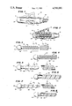
- FIG. 1 is a side elevational view of an electrode assembly which is adapted to be mounted at the distal end of a pacing lead and which includes a tip electrode.
- FIG. 2 is a partial axial sectional view of the electrode assembly shown in FIG. 1 and shows a tip electrode, a terminal pin extending rearwardly therefrom and a multifilar coil.
- FIG. 3 is a side elevational view of one embodiment of an integral tip electrode and terminal pin particularly adapted for use with a single filar coil shown adjacent thereto.
- FIG. 4 is a side elevational view of the tip electrode and terminal pin shown in FIG. 3 with the single filar coil wire wound or screwed thereon.
- FIG. 5 is a side elevational view of another embodiment of a tip electrode and terminal pin particularly for use with the multifilar coil shown in FIG. 1 and shows a terminal pin with a helical spiral ramp about which turns of several filars are wound with the multifilar coil positioned adjacent thereto.
- FIG. 6 is a side elevational view of the tip electrode and terminal pin shown in FIG. 5 with the multifilar coil wound or screwed thereon.
- FIG. 7 is a side elevational view of still another embodiment of a tip electrode and terminal pin also adapted for receiving a multifilar coil therearound with such a multifilar coil positioned adjacent thereto.
- FIG. 8 is a side elevational view of the tip electrode and terminal pin shown in FIG. 7 with the multifilar coil wound or screwed thereon.
- FIG. 1 in greater detail there is illustrated therein an electrode assembly which is generally identified by reference numeral 10.
- the electrode assembly 10 includes a tip electrode 12 at the distal end thereof and a sleeve 14 made of insulating material.
- the sleeve 14 is of the type which is provided with fins 16 and bared coiled conductive wires 18 of a pacing lead 19 are received within the sleeve 14.
- the tip electrode 12 has a mushroom shaped tip 20 and a terminal pin 22 integral therewith and extending rearwardly from the tip 20.
- the terminal pin 22 is constructed according to the teachings of the present invention and is sized and configured to receive the coils of a single wire or filar coil (see FIGS. 3 and 4) or coils of a multiwire or multifilar coil 18 therearound (see FIGS. 5-8).
- a sheath 34 of pacing lead 19 extends within the sleeve 14 and around the coil 18 which is wound or screwed onto the terminal pin 22 to form an electrical connection or termination 35.
- the tip electrode 12 which has a terminal pin 42 adapted to receive a single filar coil 44 of conductive wire.
- the single filar coil 44 is preformed with a predetermined internal diameter and a predetermined distance between each turn 46 of the coil 44.
- the terminal pin 42 is formed with thread like formation 48 including a spiral channel 50 around the pin 42 defined between each convolution of a spiral thread 52 extending outwardly from and around pin 42 at a pitch equal to that of the spiral channel 50.
- Each convolution of the spiral thread 52 is spaced a predetermined distance from the next convolution to allow convolutions of the channel 50 to receive turns 46 of the coil 44 therein.
- the channel 50 has a root diameter D which can be the same as or slightly greater than the inner diameter of the coil 44 with the pitch P 1 of the machined helical thread 52 equal to the pitch P 2 of the coil 44.
- This formation 48 provides a friction fit thereby to provide for a strong mechanical retention and better electrical connection 60 between the pin 42 and coil 44.
- the pitch P 1 of the machined helical thread 52 can be slightly greater than the pitch P 2 of the coil 44, with the pitch P 1 being selected to leave a thin web of metal on each side of the channel 50.
- FIG. 4 there is illustrated therein the terminal pin 42 of FIG. 3 with the coil 44 received on the pin 42 and in the channel 50 therein. As shown, each convolution of the thread 52 fits snugly between two turns 46 of the coil 44.
- the coil 44 is attached to pin 42 by screwing the coil 44 onto the pin 42 as one would screw a nut onto a bolt.
- the terminal pin 42 can be coated with a conductive adhesive thereby to improve the mechanical joint between pin 42 and coil 44 with no deleterious effect on the resulting electrical connection 60 formed thereby.
- FIG. 5 there is illustrated therein another embodiment of the tip electrode 12.
- a specially configured terminal pin 62 constructed to receive a multifilar coil 64 thereon is integral with and extends rearwardly from the tip 20.
- This terminal pin 62 is provided with a spiral ramp formation 66 including a helical spiral ramp 70 having a pitch P 3 equal to the pitch P 4 of the coil 64 to be received therearound. Further the width W of the ramp 70 is equal to the width of one turn 74 of the multifilar coil 64 so that each composite turn of the coil 64 fits snugly on each convolution of the ramp 70.
- each convolution of the ramp 70 varies between the inner diameter of each turn of the multifilar coil 64 and a greater diameter, i.e., it is inclined at an angle ⁇ to the axis of the pin 62 as shown to provide an interference fit between the coil 64 and ramp 70 as the coil 64 is screwed thereon thereby to provide strong mechanical retention of and good electrical connection between the coil 64 and pin 62.
- the terminal pin 62 can be coated with a suitable adhesive to improve the mechanical joint between the multifilar coil 64 and the pin 62.
- FIG. 7 Another embodiment of a tip electrode 90 with a tip 92 and a terminal pin 94 adapted for use with a multifilar coil 96 is shown in FIG. 7.
- This tip electrode 90 is very similar to the tip electrode 12 shown in FIG. 3.
- a helical channel 98 is formed about the pin 94 between convolutions of a helical thread 100 similar to the spiral channel 50 shown in FIG. 3.
- the width of the channel 98 is greater than that of the channel 50 on the terminal pin 42 to facilitate threading thereon of a multiple filar coil 96.
- the helical thread formation 100 separates the turns of the multifilar coil 96 as they are screwed onto the pin 94.
- the pitch P 5 of the helical thread 100 is equal to that of the spiral channel 98.
- the root diameter D 1 of the channel 98 is slightly greater than the inner diameter of the multifilar coil 96 to facilitate mechanical retention and better electrical connection between the multifilar coil 96 and the pin 94.
- the pitch of the machined helical thread 100 can be slightly greater than the pitch P 6 of the coil 96, with the pitch being selected to leave a thin web of metal on each side of the channel 98.
- FIG. 8 there is illustrated therein the terminal pin 94 with the coil 96 received on or threaded onto pin 94 and in the channel 98. As shown, each convolution of the thread 100 fits snugly between two turns of the coil 96.
- the coil 96 is attached to the pin 94 by screwing the coil 96 onto the pin 94 as one would screw a nut onto a bolt.
- the terminal pin 94 can be coated with a adhesive thereby to improve and enhance the mechanical joint between pin 94 and coil 96 with no deleterious effect on the resulting electrical connection 110 formed thereby.
- the pitch of the channel 50, 98 within which the single or multifilar coils 18, 44, 64, 96 are received is dependent upon the number of filars forming the particular coil 18, 44, 64, 96 which is to be received within the channel 50 or 98 or on ramp 70. It can be seen from FIG. 3 that the pitch of the single filar coil 44 is toward the terminal pin 42 while the pitch of the multifilar coil 64 or 96 shown in FIGS. 5 and 7 is away from the terminal pin. Obviously the pitch can be in either spiral direction.
- the electrode assembly 10 of the present invention and particularly the electrical connection 35, 60, 80 or 110 formed between termianl pin 22, 42, 62 or 94 and coil 18, 44, 64 or 96 provide advantages over previous coil/pin terminations or connections.
- present terminations require three components, a pin, a coil end over the pin, and a collar over the coil and pin fixed together by crimping or staking the collar. Obviously, the more components, the greater the size of the termination.
- the construction and configuration of the terminal pin of the present invention eliminates the need of one of the prior art components, i.e., namely the collar or sleeve, and provides for a smaller size termination or connection of the coil on the pin. Also the screw thread connection inhibits pulling part of the pin and coil.
- the method for attaching a coiled bare wire end portion 18, 44, 64 or 96 of a pacing lead 19 to a terminal pin or shank 22, 42, 62 or 94 extending rearwardly from a mushroom shaped or bullet shaped electrode tip 20 by means of screwing the coiled bare wire end portion 18, 44, 64 or 96 onto a helical or spiral formation 48; 66; 98, 100 on the terminal pin or shank 22, 42, 62 or 94 provides an attachment or electrical connection 35, 60, 80 or 110 which is simpler and mechanically and electrically better than the previous attachment of a conductive coil to a metal termination, e.g., pin, using a smooth pin or shank with a coil thereover and a collar or sleeve received over the coil and pin and drimped or staked thereon.
- the spiral or helical thread like formation on the pin can be configured in different ways.
- the pitch of the spiral can be made equal to the pitch of the coil or can be made greater than the pitch of the coil.
- the root diameter D of the groove or channel can be slightly greater than the root diameter of the single filar or multifilar coil to provide an interference fit.
- the pin or shank 62 is provided with a helical ramp 70 machined on it.
- the width W of the ramp is equal to the width of the filars so that the filars sit side by side on the ramp 70.
- the pitch of the helical ramp 70 is equal to the pitch of the filars.
- the ramp 70 is inclined so as to have a varying diameter starting with a diameter equal to or slightly less than the inner diameter of the coil 64 and extending to a diameter greater than the inner diameter of the coil 64.
- the spiral channel 98 has a flat bottom and is machined onto the pin or shank 94.
- the width of the channel 98 is equal to the width of the filars in each turn of the coil 96.
- the pitch of the helical thread 100 is then selected to leave a thin web of metal on each side of the channel 98.
- the electrical connection of the present invention has a number of advantages some of which have been described above and others of which are inherent in the invention. Also, modifications can be made to the invention without departing from the teachings of the invention.
- the electrical connection can be used in a coil termination at the proximal end of a pacing lead oetween a terminal such as a terminal pin and one or more bare end coiled filars. Accordingly, the scope of the invention is only to be limited as necessitated by the accompanying claims.
Landscapes
- Electrotherapy Devices (AREA)
Abstract
Description
______________________________________
U.S. PAT. NO.        PATENTEE
______________________________________
1,584,533            Hands
1,779,804            Dubilier
2,104,888            Sparh
2,759,166            Mallina
2,792,560            Bollmeier
3,243,755            Johnston
3,649,743            O'Loughlin
______________________________________
Claims (13)
Priority Applications (1)
| Application Number | Priority Date | Filing Date | Title |
|---|---|---|---|
| US06/491,401 US4541681A (en) | 1983-05-04 | 1983-05-04 | Electrical connection of wire conductor(s) to a terminal pin in an electrode assembly of a pacing lead |
Applications Claiming Priority (1)
| Application Number | Priority Date | Filing Date | Title |
|---|---|---|---|
| US06/491,401 US4541681A (en) | 1983-05-04 | 1983-05-04 | Electrical connection of wire conductor(s) to a terminal pin in an electrode assembly of a pacing lead |
Publications (1)
| Publication Number | Publication Date |
|---|---|
| US4541681A true US4541681A (en) | 1985-09-17 |
Family
ID=23952061
Family Applications (1)
| Application Number | Title | Priority Date | Filing Date |
|---|---|---|---|
| US06/491,401 Expired - Fee Related US4541681A (en) | 1983-05-04 | 1983-05-04 | Electrical connection of wire conductor(s) to a terminal pin in an electrode assembly of a pacing lead |
Country Status (1)
| Country | Link |
|---|---|
| US (1) | US4541681A (en) |
Cited By (23)
| Publication number | Priority date | Publication date | Assignee | Title |
|---|---|---|---|---|
| US4889496A (en) * | 1988-04-12 | 1989-12-26 | Intercon Systems, Inc. | Compressible core electrical connector |
| US4942876A (en) * | 1988-08-02 | 1990-07-24 | Telectronics, N.V. | Pacemaker terminal apparatus |
| US4943289A (en) * | 1989-05-03 | 1990-07-24 | Cook Pacemaker Corporation | Apparatus for removing an elongated structure implanted in biological tissue |
| US4988347A (en) * | 1988-11-09 | 1991-01-29 | Cook Pacemaker Corporation | Method and apparatus for separating a coiled structure from biological tissue |
| US5013310A (en) * | 1988-11-09 | 1991-05-07 | Cook Pacemaker Corporation | Method and apparatus for removing an implanted pacemaker lead |
| US5069209A (en) * | 1990-09-21 | 1991-12-03 | Telectronics Pacing Systems, Inc. | Electrical terminal |
| US5207683A (en) * | 1988-11-09 | 1993-05-04 | Cook Pacemaker Corporation | Apparatus for removing an elongated structure implanted in biological tissue |
| US5507751A (en) * | 1988-11-09 | 1996-04-16 | Cook Pacemaker Corporation | Locally flexible dilator sheath |
| US5697936A (en) * | 1988-11-10 | 1997-12-16 | Cook Pacemaker Corporation | Device for removing an elongated structure implanted in biological tissue |
| US6136005A (en) * | 1988-11-09 | 2000-10-24 | Cook Pacemaker Corporation | Apparatus for removing a coiled structure implanted in biological tissue, having expandable means including a laterally deflectable member |
| US6167315A (en) * | 1999-04-05 | 2000-12-26 | Spectranetics Corporation | Lead locking device and method |
| WO2002061886A1 (en) * | 2001-01-31 | 2002-08-08 | Che-Yu Li | Contact assembly for land grid array interposer or electrical connector |
| US6712826B2 (en) | 2000-05-17 | 2004-03-30 | Cook Vascular Incorporated | Apparatus for removing an elongated structure implanted in biological tissue |
| US20040236396A1 (en) * | 1999-04-05 | 2004-11-25 | Coe Michael Sean | Lead locking device and method |
| US20040236397A1 (en) * | 1999-04-05 | 2004-11-25 | The Spectranetics Corporation | Lead locking device and method |
| US20050192591A1 (en) * | 2004-02-27 | 2005-09-01 | Lui Chun K. | Device for removing an elongated structure implanted in biological tissue |
| US20050246010A1 (en) * | 2004-04-30 | 2005-11-03 | Novostent Corporation | Delivery catheter that controls foreshortening of ribbon-type prostheses and methods of making and use |
| US20060155352A1 (en) * | 1999-04-05 | 2006-07-13 | Bowe Wade A | Lead locking device and method |
| US20070191919A1 (en) * | 2006-02-13 | 2007-08-16 | Cook Vascular Incorporated | Device and method for removing lumenless leads |
| US20070259562A1 (en) * | 2006-05-02 | 2007-11-08 | Michael Holland | Compression connector for stranded wire |
| US20100331937A1 (en) * | 2009-06-30 | 2010-12-30 | Foster Arthur J | Active fixation lead with helix securement mechanism |
| US10937752B1 (en) * | 2020-08-03 | 2021-03-02 | Topline Corporation | Lead free solder columns and methods for making same |
| US12526920B1 (en) | 2024-01-12 | 2026-01-13 | Topline Corporation | Indium-niobium superconducting solder columns for cryogenic and quantum computer applications and methods for making same |
Citations (12)
| Publication number | Priority date | Publication date | Assignee | Title |
|---|---|---|---|---|
| US1584533A (en) * | 1922-10-28 | 1926-05-11 | Westinghouse Electric & Mfg Co | Terminal for resistors |
| US1779804A (en) * | 1926-11-01 | 1930-10-28 | Radio Patents Corp | Lamp socket |
| US2104888A (en) * | 1933-10-16 | 1938-01-11 | Spahr Otto | Electrical connecting device |
| US2353222A (en) * | 1941-12-13 | 1944-07-11 | Augusta P Coolbroth | Purse, handbag, or the like |
| US2759166A (en) * | 1952-06-20 | 1956-08-14 | Bell Telephone Labor Inc | Wrapped electrical connection |
| US2792560A (en) * | 1953-03-23 | 1957-05-14 | Minnesota Mining & Mfg | Wire-connector |
| US3243755A (en) * | 1964-03-16 | 1966-03-29 | Gen Electric | Electrical connector |
| US3262085A (en) * | 1964-09-21 | 1966-07-19 | Slick Electro Inc | Terminal means for ignition cables |
| US3649743A (en) * | 1970-09-01 | 1972-03-14 | Thomas & Betts Corp | Wrapped wire connection |
| US4000745A (en) * | 1968-08-05 | 1977-01-04 | Goldberg Edward M | Electrical leads for cardiac stimulators and related methods and means |
| US4091233A (en) * | 1976-08-23 | 1978-05-23 | Berman Alfred J | Electrical connector and method of connecting an electrical cable to same |
| US4316646A (en) * | 1980-02-04 | 1982-02-23 | Amerace Corporation | Laterally flexible electrical connector assembly |
-
1983
- 1983-05-04 US US06/491,401 patent/US4541681A/en not_active Expired - Fee Related
Patent Citations (12)
| Publication number | Priority date | Publication date | Assignee | Title |
|---|---|---|---|---|
| US1584533A (en) * | 1922-10-28 | 1926-05-11 | Westinghouse Electric & Mfg Co | Terminal for resistors |
| US1779804A (en) * | 1926-11-01 | 1930-10-28 | Radio Patents Corp | Lamp socket |
| US2104888A (en) * | 1933-10-16 | 1938-01-11 | Spahr Otto | Electrical connecting device |
| US2353222A (en) * | 1941-12-13 | 1944-07-11 | Augusta P Coolbroth | Purse, handbag, or the like |
| US2759166A (en) * | 1952-06-20 | 1956-08-14 | Bell Telephone Labor Inc | Wrapped electrical connection |
| US2792560A (en) * | 1953-03-23 | 1957-05-14 | Minnesota Mining & Mfg | Wire-connector |
| US3243755A (en) * | 1964-03-16 | 1966-03-29 | Gen Electric | Electrical connector |
| US3262085A (en) * | 1964-09-21 | 1966-07-19 | Slick Electro Inc | Terminal means for ignition cables |
| US4000745A (en) * | 1968-08-05 | 1977-01-04 | Goldberg Edward M | Electrical leads for cardiac stimulators and related methods and means |
| US3649743A (en) * | 1970-09-01 | 1972-03-14 | Thomas & Betts Corp | Wrapped wire connection |
| US4091233A (en) * | 1976-08-23 | 1978-05-23 | Berman Alfred J | Electrical connector and method of connecting an electrical cable to same |
| US4316646A (en) * | 1980-02-04 | 1982-02-23 | Amerace Corporation | Laterally flexible electrical connector assembly |
Cited By (35)
| Publication number | Priority date | Publication date | Assignee | Title |
|---|---|---|---|---|
| US4889496A (en) * | 1988-04-12 | 1989-12-26 | Intercon Systems, Inc. | Compressible core electrical connector |
| US4942876A (en) * | 1988-08-02 | 1990-07-24 | Telectronics, N.V. | Pacemaker terminal apparatus |
| US4988347A (en) * | 1988-11-09 | 1991-01-29 | Cook Pacemaker Corporation | Method and apparatus for separating a coiled structure from biological tissue |
| US5013310A (en) * | 1988-11-09 | 1991-05-07 | Cook Pacemaker Corporation | Method and apparatus for removing an implanted pacemaker lead |
| US5207683A (en) * | 1988-11-09 | 1993-05-04 | Cook Pacemaker Corporation | Apparatus for removing an elongated structure implanted in biological tissue |
| US5507751A (en) * | 1988-11-09 | 1996-04-16 | Cook Pacemaker Corporation | Locally flexible dilator sheath |
| US5632749A (en) * | 1988-11-09 | 1997-05-27 | Cook Pacemaker Corporation | Apparatus for removing an elongated structure implanted in biological tissue |
| US6136005A (en) * | 1988-11-09 | 2000-10-24 | Cook Pacemaker Corporation | Apparatus for removing a coiled structure implanted in biological tissue, having expandable means including a laterally deflectable member |
| US5697936A (en) * | 1988-11-10 | 1997-12-16 | Cook Pacemaker Corporation | Device for removing an elongated structure implanted in biological tissue |
| US4943289A (en) * | 1989-05-03 | 1990-07-24 | Cook Pacemaker Corporation | Apparatus for removing an elongated structure implanted in biological tissue |
| US5069209A (en) * | 1990-09-21 | 1991-12-03 | Telectronics Pacing Systems, Inc. | Electrical terminal |
| US7499756B2 (en) | 1999-04-05 | 2009-03-03 | Spectranetics | Lead locking device and method |
| US20060155352A1 (en) * | 1999-04-05 | 2006-07-13 | Bowe Wade A | Lead locking device and method |
| US8428747B2 (en) | 1999-04-05 | 2013-04-23 | The Spectranetics Corp. | Lead locking device and method |
| US6324434B2 (en) | 1999-04-05 | 2001-11-27 | Spectranetics Corporation | Lead locking device and method |
| US6167315A (en) * | 1999-04-05 | 2000-12-26 | Spectranetics Corporation | Lead locking device and method |
| US20040236396A1 (en) * | 1999-04-05 | 2004-11-25 | Coe Michael Sean | Lead locking device and method |
| US20040236397A1 (en) * | 1999-04-05 | 2004-11-25 | The Spectranetics Corporation | Lead locking device and method |
| US6712826B2 (en) | 2000-05-17 | 2004-03-30 | Cook Vascular Incorporated | Apparatus for removing an elongated structure implanted in biological tissue |
| KR100905736B1 (en) * | 2001-01-31 | 2009-07-01 | 하이 커넥션 덴서티, 인코포레이티드 | Contact assembly for land grid array interposer or electrical connector |
| US6659778B2 (en) | 2001-01-31 | 2003-12-09 | High Connection Density, Inc | Contact assembly for land grid array interposer or electrical connector |
| WO2002061886A1 (en) * | 2001-01-31 | 2002-08-08 | Che-Yu Li | Contact assembly for land grid array interposer or electrical connector |
| CN100477388C (en) * | 2001-01-31 | 2009-04-08 | 高度连接密度公司 | Contact assembly, and insertor or electrical connector using the contact assembly |
| US6439894B1 (en) * | 2001-01-31 | 2002-08-27 | High Connection Density, Inc. | Contact assembly for land grid array interposer or electrical connector |
| US20050192591A1 (en) * | 2004-02-27 | 2005-09-01 | Lui Chun K. | Device for removing an elongated structure implanted in biological tissue |
| US20050246010A1 (en) * | 2004-04-30 | 2005-11-03 | Novostent Corporation | Delivery catheter that controls foreshortening of ribbon-type prostheses and methods of making and use |
| US7766960B2 (en) * | 2004-04-30 | 2010-08-03 | Novostent Corporation | Delivery catheter that controls foreshortening of ribbon-type prostheses and methods of making and use |
| US8128636B2 (en) | 2006-02-13 | 2012-03-06 | Cook Medical Technologies Llc | Device and method for removing lumenless leads |
| US20070191919A1 (en) * | 2006-02-13 | 2007-08-16 | Cook Vascular Incorporated | Device and method for removing lumenless leads |
| US20070259562A1 (en) * | 2006-05-02 | 2007-11-08 | Michael Holland | Compression connector for stranded wire |
| US7500868B2 (en) * | 2006-05-02 | 2009-03-10 | Michael Holland | Compression connector for stranded wire |
| US20100331937A1 (en) * | 2009-06-30 | 2010-12-30 | Foster Arthur J | Active fixation lead with helix securement mechanism |
| US8543224B2 (en) | 2009-06-30 | 2013-09-24 | Cardiac Pacemakers, Inc. | Active fixation lead with helix securement mechanism |
| US10937752B1 (en) * | 2020-08-03 | 2021-03-02 | Topline Corporation | Lead free solder columns and methods for making same |
| US12526920B1 (en) | 2024-01-12 | 2026-01-13 | Topline Corporation | Indium-niobium superconducting solder columns for cryogenic and quantum computer applications and methods for making same |
Similar Documents
| Publication | Publication Date | Title |
|---|---|---|
| US4541681A (en) | Electrical connection of wire conductor(s) to a terminal pin in an electrode assembly of a pacing lead | |
| FI103841B (en) | Flexible connector for coaxial cables with threaded outer conductor | |
| US4538623A (en) | Thread electrode assembly | |
| EP0484434B1 (en) | Cable collet termination | |
| US5322454A (en) | Connector for helically corrugated conduit | |
| US4720157A (en) | Electrical connector having resilient contact means | |
| US4592372A (en) | Pacing/sensing electrode sleeve and method of forming same | |
| US4463765A (en) | Screw-in pacing lead assembly | |
| US4468083A (en) | Crimped banana-type electrical connector and method thereof | |
| JP2777343B2 (en) | Connecting terminal | |
| US6162995A (en) | Armored electrical cable connector | |
| US4613199A (en) | Direct-crimp coaxial cable connector | |
| KR960000127B1 (en) | High voltage cable connector | |
| JPS59211976A (en) | Drawing device of coaxial cable core and connector with samedrawing device | |
| JP3673527B2 (en) | Shield wire connection terminal | |
| WO2004028619B1 (en) | Methods and apparatus for joining small diameter conductors within medical electrical leads | |
| CA2198100A1 (en) | Implantable endocardial lead with self-healing retractable fixation apparatus | |
| US7890184B2 (en) | Conductor junctions for medical electrical leads | |
| US3456064A (en) | Connectors for flexible welding cable assemblies | |
| US2681440A (en) | Electrical connector | |
| JP2004055475A (en) | Connection structure between coaxial cable and coaxial connector | |
| US6478606B1 (en) | Twist-on connector with a heat-shrinkable skirt | |
| US4659164A (en) | Diode connector | |
| US5562482A (en) | Coaxial cable connector and method of assembling | |
| US4035577A (en) | Tubular ferrule |
Legal Events
| Date | Code | Title | Description |
|---|---|---|---|
| AS | Assignment |
Owner name: CORDIS CORPORATION, 10555 WEST FLAGLER ST., MIAMI, Free format text: ASSIGNMENT OF ASSIGNORS INTEREST.;ASSIGNORS:DORMAN, FREDERICK S.;PEERS-TREVARTON, CHARLES A.;REEL/FRAME:004127/0032 Effective date: 19830426 |
|
| AS | Assignment |
Owner name: SOUTHEAST BANK, N.A., MIDLAD BANK PLC (SINGAPORE B Free format text: SECURITY INTEREST;ASSIGNOR:CORDIS LEADS, INC., A CORP. OF DE;REEL/FRAME:004747/0320 Effective date: 19870612 |
|
| AS | Assignment |
Owner name: SOUTHEAST BANK, N.A., MIDLAND BANK PLC (SINGAPORE Free format text: SECURITY INTEREST;ASSIGNOR:CORDIS HEADS, INC.;REEL/FRAME:004734/0550 Effective date: 19870630 |
|
| AS | Assignment |
Owner name: CORDIS LEADS, INC., 10555 WEST FLAGLER STREET, MIA Free format text: ASSIGNMENT OF ASSIGNORS INTEREST.;ASSIGNOR:CORDIS CORPORATION, A CORP. OF FLORIDA;REEL/FRAME:004747/0313 Effective date: 19870430 Owner name: CORDIS LEADS, INC., FLORIDA Free format text: ASSIGNMENT OF ASSIGNORS INTEREST;ASSIGNOR:CORDIS CORPORATION, A CORP. OF FLORIDA;REEL/FRAME:004747/0313 Effective date: 19870430 |
|
| AS | Assignment |
Owner name: SOUTHEAST BANK, N.A. Free format text: SECURITY INTEREST;ASSIGNOR:CORDIS LEADS, INC., A DE CORP.;REEL/FRAME:004896/0205 Effective date: 19880602 |
|
| AS | Assignment |
Owner name: SOUTHEAST BANK, N.A., AS SECURITY AGENT Free format text: SECURITY INTEREST;ASSIGNOR:CORDIS LEADS, INC., A CORP. OF DE;REEL/FRAME:004896/0372 Effective date: 19880610 |
|
| AS | Assignment |
Owner name: CORDIS LEADS, INC., 10555 W. FLAGLER STR., MIAMI, Free format text: RELEASED BY SECURED PARTY;ASSIGNOR:SOUTHEAST BANK, N.A., MIDLAND BANK PLC AND CREDIT LYONNAIS;REEL/FRAME:004996/0829 Effective date: 19880615 Owner name: TPL-CORDIS, INC., A DE CORP., FLORIDA Free format text: NUNC PRO TUNC ASSIGNMENT;ASSIGNOR:CORDIS LEADS, INC.;REEL/FRAME:005003/0158 Effective date: 19881130 Owner name: TELECTRONICS, INC., A DE CORP., CONNECTICUT Free format text: NUNC PRO TUNC ASSIGNMENT;ASSIGNOR:TPL-CORDIS, INC.;REEL/FRAME:005003/0166 Effective date: 19881130 |
|
| FEPP | Fee payment procedure |
Free format text: PAYOR NUMBER ASSIGNED (ORIGINAL EVENT CODE: ASPN); ENTITY STATUS OF PATENT OWNER: LARGE ENTITY |
|
| FPAY | Fee payment |
Year of fee payment: 4 |
|
| AS | Assignment |
Owner name: TELECTRONICS, U.S.A., INC., CONNECTICUT Free format text: RELEASED BY SECURED PARTY;ASSIGNOR:SOUTHEAST BANK N.A.;REEL/FRAME:005181/0530 Effective date: 19890831 |
|
| AS | Assignment |
Owner name: TELECTRONICS PACING SYSTEMS, INC., COLORADO Free format text: ASSIGNORS HEREBY CONFIRMS THE ENTIRE INTEREST IN SAID INVENTIONS TO ASSIGNEE ELECUTED ON SEPT. 16, 1988;ASSIGNORS:TELECTRONICS PTY. LTD.;MEDICAL TELECTRONICS HOLDING & FINANCE CO.;TELECTRONIC NV;AND OTHERS;REEL/FRAME:006172/0028 Effective date: 19920622 |
|
| LAPS | Lapse for failure to pay maintenance fees | ||
| FP | Lapsed due to failure to pay maintenance fee |
Effective date: 19930919 |
|
| AS | Assignment |
Owner name: TELECTRONICS PACING SYSTEMS, INC., COLORADO Free format text: CORRECTIVE ASSIGNMENT TO CORRECT ASSIGNEE'S STATE OF INCORPORATION. AN ASSIGNMENT WAS PREVIOUSLY RECORDED AT REEL 6172, FRAME 0028;ASSIGNORS:TELECTRONICS PTY. LTD., AN AUSTRALIAN COMPANY;MEDICAL TELECTRONICS HOLDING & FINANCE CO. (BV), A DUTCH COMPANY;TELECTRONICS NV, A COMPANY OF THE NETHERLANDS ANTILLES;AND OTHERS;REEL/FRAME:008321/0072 Effective date: 19961101 |
|
| STCH | Information on status: patent discontinuation |
Free format text: PATENT EXPIRED DUE TO NONPAYMENT OF MAINTENANCE FEES UNDER 37 CFR 1.362 |