US454150A - Check-row attachment for corn-planters - Google Patents
Check-row attachment for corn-planters Download PDFInfo
- Publication number
- US454150A US454150A US454150DA US454150A US 454150 A US454150 A US 454150A US 454150D A US454150D A US 454150DA US 454150 A US454150 A US 454150A
- Authority
- US
- United States
- Prior art keywords
- shaft
- sprocket
- wheels
- track
- car
- Prior art date
- Legal status (The legal status is an assumption and is not a legal conclusion. Google has not performed a legal analysis and makes no representation as to the accuracy of the status listed.)
- Expired - Lifetime
Links
- 230000007246 mechanism Effects 0.000 description 12
- 238000010276 construction Methods 0.000 description 5
- 230000009471 action Effects 0.000 description 4
- 241000282472 Canis lupus familiaris Species 0.000 description 3
- 244000100170 Phaseolus lunatus Species 0.000 description 3
- 240000008042 Zea mays Species 0.000 description 2
- 235000005824 Zea mays ssp. parviglumis Nutrition 0.000 description 2
- 235000002017 Zea mays subsp mays Nutrition 0.000 description 2
- 235000005822 corn Nutrition 0.000 description 2
- 230000008878 coupling Effects 0.000 description 2
- 238000010168 coupling process Methods 0.000 description 2
- 238000005859 coupling reaction Methods 0.000 description 2
- 230000000284 resting effect Effects 0.000 description 2
- 240000000467 Carum carvi Species 0.000 description 1
- 235000005747 Carum carvi Nutrition 0.000 description 1
- 241000196324 Embryophyta Species 0.000 description 1
- 240000001931 Ludwigia octovalvis Species 0.000 description 1
- 229910000754 Wrought iron Inorganic materials 0.000 description 1
- WHGYBXFWUBPSRW-FOUAGVGXSA-N beta-cyclodextrin Chemical compound OC[C@H]([C@H]([C@@H]([C@H]1O)O)O[C@H]2O[C@@H]([C@@H](O[C@H]3O[C@H](CO)[C@H]([C@@H]([C@H]3O)O)O[C@H]3O[C@H](CO)[C@H]([C@@H]([C@H]3O)O)O[C@H]3O[C@H](CO)[C@H]([C@@H]([C@H]3O)O)O[C@H]3O[C@H](CO)[C@H]([C@@H]([C@H]3O)O)O3)[C@H](O)[C@H]2O)CO)O[C@@H]1O[C@H]1[C@H](O)[C@@H](O)[C@@H]3O[C@@H]1CO WHGYBXFWUBPSRW-FOUAGVGXSA-N 0.000 description 1
- 230000000881 depressing effect Effects 0.000 description 1
- 230000000994 depressogenic effect Effects 0.000 description 1
- 230000006872 improvement Effects 0.000 description 1
- 230000001105 regulatory effect Effects 0.000 description 1
- 230000002441 reversible effect Effects 0.000 description 1
- 239000002689 soil Substances 0.000 description 1
Images


Classifications
-
- A—HUMAN NECESSITIES
- A01—AGRICULTURE; FORESTRY; ANIMAL HUSBANDRY; HUNTING; TRAPPING; FISHING
- A01C—PLANTING; SOWING; FERTILISING
- A01C7/00—Sowing
- A01C7/18—Machines for depositing quantities of seed at intervals
Definitions
- This invention relates to check-row attachments for corn-planters; and it has for its object to provide a device-of this class which shall be simple in construction, andavhich may be readily applied to any ordinary cornplanter that is provided with a reciprocating seed-slide to drop the contents of the hoppers, and which shall serve as the machine passes over the ground to automatically operate the seed-dropping mechanism and the marking devices.
- a further object of the invention is to so construct the attachment that the operation of the marking devices may be timed to take place simultaneously with the seed-dropping mechanism, thus avoiding irregularities in each subsequent passage of the machine over the field.
- Figure 1 is a plan, partly broken away, of a corn-planter constructed in accordance with my invention.
- Fig. 2 is a transverse section of the same on the line 2 2 of Fig. 1, looking in the direction of the arrow.
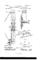
- Fig. 3 is a side elevation of the hopper and shoe with my improvement applied.
- Fig. 4 is a detail view in perspective of the bracket 68.
- Fig. 5 is an enlarged plan view of the ear and track at the rear end of the machine.
- Fig. 6 is a detail in perspective of one of the trusses for supporting the track]
- Fig. 7 is a detail view in plan of one of the king-links.
- Fig. 1 is a plan, partly broken away, of a corn-planter constructed in accordance with my invention.
- Fig. 2 is a transverse section of the same on the line 2 2 of Fig. 1, looking in the direction of the arrow.
- Fig. 3 is a side elevation of the hopper
- Fig. 8 is a detail in longitudinal section on the line 8 8 of Fig. 1.
- Figs. 9 and 10 are front and rear elevations, respectively, of the seed-slide-operating plate.
- Fig. 11 is a horizontal sectional view on the line 11 11 of Fig. 9.
- Fig. 12 is a transverse central section through the track and car.
- Fig. 13 is alongitudinal sectional view through the car, taken on the line 13 13 in Fig. 5.
- 1 designates the frame of acorn-planter to which my improved check-rowing device has been attached in position for operation.
- FIG. 2 designates an oblong or elliptical track, which is composed of the parallel side pieces 3 3, connected by the curved ends 4, the entire track being preferably constructed of a strip of bar-iron of suitable dimensions bent to the desired shape and set on edge, as will be readily understood by reference to the drawings.
- This track is provided with suitable cross-pieces or truss-rods 5, and it is suitably attached in any convenient manner to the longitudinal frame-bars 6 of the machine.
- the sides 3 3 of the track are provided near their ends with bearings for the shafts 77, carrying sprocket-Wheels 8.
- the shaft 7 at one end of the track is extended through the front side of the latter, and is provided with a miter-gear 9, meshing with a pinion 10, which is mounted securely upon a shaft 11, which is journaled in a bracket 12, extending forwardly from the front track-bar 3, to which latter it is bolted or otherwise suitably secured.
- a laterally-sliding sprocket-wheel 13 the hub of which is provided on its inner side with an annularly-grooved collar 14 and on its outer side with a clutch member 15.
- the latter is adapted to engage the clutch-collar 16, which is rigidly secured upon the shaft 11.
- the sprocket-Wheel 13 is connected by a chain 17 with a sprocket-wheel 18, which is suitably attached to one of the transporting-Wheels 19 of the corn-planter. It will thus be seen that when the machine is in operation motion may be transmitted from one of the transportingwheels to the shaft 11 and from the latter to the shafts 7 through the miter-gearing 9 10.
- a suitable operating-lever 20, havinga bifurcated end, is arranged to engage the annularly-grooved collar 1-l of the sprocket-wheel 13 in order to throw the clutch member 15 of the latterinto or out of engagement with the clutch-collar 16 to regulate the operation of the machine.
- a device which I designate the car or carriage 21, and which is composed of the ends 22 and sides 23, which latter are provided at their upper edges with flanges 24, resting upon the upper edges of the side pieces 3 of the track.
- the ends of the frame of the sliding car 21 are provided with vertically-adjustable arms or brackets 32, having bearings for the shafts 33, which are arranged transversely to the frame of the car, but longitudinally with the frame of the planter. These shafts are provided with sprocket-wheels 34.
- the sides of the frame of the car 21 are also provided with bearings for a shaft 35, located centrally between and parallel to the shafts 33.
- the shaft 35 carries a sprocket-wheel 36, which is journaled loosely thereon, and upon the said shaft, adjacent to the sides of said sprocketwheel, are secured the ratchet-wheels 37.
- Arms or levers 38 having bifurcated inner ends, are pivotally mounted upon the shaft 35 between the ratchet-wheels 37 and the sides 23 of the frame of the car. These levers are provided with pivoted dogs or pawls 39, engaging the ratehet-wheels 37 and held in engagement with the latter by the action of suitably-arranged springs. Springs 40, which are coiled upon the shaft 35 between the arms of the bifurcated levers 38, also serve to hold the latter normally in a depressed position, with their outer or free ends resting upon the upper edge of 'one of the end pieces 22 of the frame of the car.
- the sprocket-wheels 34 are simply guide-wheels or idlers that serve to properly guide the said sprocket-chain and to hold the links of the latter in engagement with the teeth of the sprocket-wheel 30.
- the brackets in which the shafts of the said guidesprockets are mounted are also made vertically adjustable, as above described, in order to enable slack in the chain to be taken up when necessary.
- the chain 41 which is mounted upon the several sprocket-wheels, as just described, and which receives motion through the mitergearing 9 10, shaft 11, and through the sprocket-wheel and clutch mechanism upon the said shaft from one of the transporting-wheels 19 of the machine, is provided at suitable intervals with specially-construeted king-links 42, having laterally-extending flanges 43, adapted to engage the free ends of the bifurcated levers 38, thus raising the latter and causing the pawls of said levers to engage the ratchetwheels 37 and to partly rotate the shafts upon which the said ratchetwheels are mounted.
- the said shaft 35 is extended through the front side of the frame of the car 21, and is connected by a universal joint or coupling it with a longitudinal shaft 45, the front end of which is in turn connected by a universal joint 46 with a short shaft 47, which is suitably journaled in a, plate 48, that is bolted or otherwise attached to one of the cross-bars of the frame of the corn-planter between the seed-boxes or hoppers 49.
- the sides or edges of the plate 48 are provided with flanges 49', forming bearings for the vertically-sliding plates 50, having pins or studs 51 extending rearwardly through slots 52 in the plate 48'.
- the studs 51 are connected in rear of said plate by springs 53, serving to draw the said plates closely together.
- the shaft 47 carries at its front end an elliptical plate or cam 54, which is fitted between the sliding plate 50, the inner edges of which are fitted to the sides of said elliptical cam.
- the latter has a slot 55, in which is mounted an adjustable wrist-pin 56, connected by a pitman 57 with the seed-slide 58 of the cornplanter, which is in this manner operated.
- a transverse shaft 60 Suitably attached to the front sides of the shoes or runners 59 of the corn-planter is a transverse shaft 60, upon the ends of which are adjustably mounted the arms or handles 61 of the markers 62, said arms or handles being provided with series of perforations 63 for connection with the said shaft.
- the markers 62 are made reversible, and are provided at opposite ends with sharp edges or points M and with blunt heads 65, either of which may be used for marking purposes, according to the nature of the soil.
- the vertically-adjustable sleeves 67 Suitably mounted upon the seed-spouts 66 are the vertically-adjustable sleeves 67, having brackets 68, provided with vertical slots 69 and with laterallyextending arms 70.
- the levers 71 Loosely mounted in the slots 69 are the levers 71, the outer ends of which have downwardly-extending arms 72, to which are pivotally connected the markers 62 by means 0f the pins or bolts 73.
- the inner ends of the le vers 71 are extended over a link or cross-bar 74, which is suitably mounted upon the shaft 47 in rear of the plate 48.
- Springs 75 connect the levers 71 with the arms 70, extending laterally from the brackets '68 for the purpose of holding the inner ends of the said levers normally in position for operation in contact with the upper side of the link or cross-bar 74.
- the apparatus which comprises my invention may be readily attached by means of bolts, clips, or other well-known devices to the frame of any corn-planter to which it is applicable.
- Motion is transmitted from one of the transporting-wheels 19 of the machine to the endless sprocket-chain 41, which is guided over the sprocket-wheels 8, 34, and 36, to which latter motion is thus transmitted.
- the flanged king-links of the said chain will intermittently engage the free ends of the bifurcated levers 38, thus imparting through the said levers, the pawls 39, and ratchetwheels 37 a partial rotary motion to the shaft 35 and through the latter and the universally-jointed connection 45 to the shaft 47.
- the pitman 57 connected with the cam 54 upon the said shaft 47, will impart an inter mittent reciprocating motion to the seed-slide 58, thus operating the seed-dropping mechanism, which may be of any well-known construction, and which does not form a part of the present invention; It is of course essential to the successful operation of the device that the shaft 47 should make exactlya onehalf revolution at each operation.
- This adjustment may be very easily and quickly accomplished by the driver by means of the shaft having the crank 30.
- a shaft mount- 3 ed inthe said carriage means for intermittently operating the said shaft, and means for transmitting motion from the latter to the seed-dropping and marking mechanisms of the planter, substantially as set forth.
- a suitable supporting-track a car or carriage mounted adjustably upon the latter, a shaft mounted in the said carriage, a sprocket-wheel mounted loosely uponthe said shaft, ratchet-wheels mounted upon said shaft adjacentto the sides of the sprocket-wheels, the levers mounted pivotally upon said shaft and having dogs or pawls engaging the said vratchetwheels, an endless sprocket-chain having flanged links adapted to engage the levers having the dogs or pawls, suitable supporting and guiding wheels for the said chain, and means for transmitting motion to the latter from one of the transporting-wheels of the machine, substan tially as and for the purpose set forth.
- I11 a device of the class described, the combination, with a suitable supporting-track, of the carriage mounted adjustably upon the same and having the intermittently-revoluble shaft, and mechanism for transmitting motion from the latter to the seed-dropping and marking mechanisms and for adjusting the car or carriage upon the track, substantially as and for the purpose set forth.
- the combination of the supporting-track, the adj ustable car or carriage having the intermittently-revoluble shaft means, substantially as described, for adjusting the carriage and for transmittin motion.
- a shaft having a cam provided with a wrist-pin connected by a pitman with the seed-slide, a cross-bar or link engaging the inner ends of the markinglevers,and aconnecting-rod having its ends connected by universal joints or couplings with the rear end of the latter shaft and with the front end of the intermittently-revoluble shaft in the adjustable carriage, substantially as and for the purpose set forth.
- a suitable bracket upon the front side of the track and having a bevel- Whccl, a fixed clutch-collar, a laterally-sliding sprocket-wheel provided with a clutch member, means for adjusting said sprocketwheel, a chain connecting the latter with a sprocket-wheel upon one of the transportingwheels, an endless sprocket-chain having the flanged king-links to transmit an intermittent rotary motion to the shaft journaled in the sides of the carriage, and means for transmitting motion from the said shaft to the seed-dropping and marking mechanisms, substantially as set forth.
- the combination of the sup )orting-track, the ad j ustable car or carriage having the intermittently-revoluble shaft, a frame or plate provided with vertical flanges, a shaftjournaled in said plate and having its rear end connected by a universally-jointed coupling-rod with the front end of the intermittently-revoluble shaft in the adjustable carriage, an elliptical cam mounted upon the shaft journaled in the flanged plate or frame, the plates mounted slidingly in the latter and having curved inner edges and rearwardly-extending studs projecting through slots in the flanged frame or plate, the springs connecting the rearwardly-extending studs of the sliding plates, a wrist-pin mounted adjustably in a slot in the elliptical cam, a pitman connecting said Wrist-pin with the seed-s1ide,a crossbar mounted upon the longitudinal shaft in rear of the elliptical cam, and the markinglevers engaged and operated by the said crossbar
- a device of the class described the combination of a cross-bar attached to the runners of the planter, the marking-hoes mounted adjustably upon said cross-bar, the sleeves or collars mounted adjustably upon the seed-spouts and having brackets provided with vertical slots and laterally-extending arms, the levers mounted loosely in said slots and having their outer ends connected pivotally with the markers, the springs connecting said lovers with the laterally-extending arms of the supporting-brackets, and the intermittently-revoluble shaft having a link or cross-bar arranged under and adapted to engage the overlapping inner ends of the levers, substantially as and for the purpose set forth.
Landscapes
- Life Sciences & Earth Sciences (AREA)
- Soil Sciences (AREA)
- Environmental Sciences (AREA)
- Agricultural Machines (AREA)
Description
- (No Model.) 4 Sheets-Sheet 1.
0. s. BEAN. CHECK ROW ATTACHMENT FOR CORN PLAN-TEES. No. 454,150. Patented June 16,1891.
F! G .l'
Caraway. Few
o m y: 5 m A a If w w pm 3% m 9 W 1 4 w i MW l W 4 Sheets-Shet 2.
(No Model) 0. S. BEAN. CHECK ROW ATTACHMENT FOR 001m PLANTERS. No. 454,150.
Patented June 16,1891.
m: nunms versus cm, mmu'mu fwmmarw, u. c.
4 sheets sheet 3.
Patented June 16, 1891.
A 19961316? (krltoiaSlfim/ $57112) hi'fim eys,
(No Model.)
0. S. BEAN. GHEGK ROW ATTACHMENT FOR CORN PLANTERS.
gwwmzzw m2 mama warms cc mum-mm, vlAsmnumn, n. c.
'4 Shets-Sheet 4.
(No Model.) O. S. BEAN.
GHEOK ROW ATTACHMENT FOR CORN PLANTEHS.
Patented June 16,1891;
FIG-lln. 4.- III/IIIIIIl/lllll/llllllm @rlio 72/15 B 601/.
UNITED STATES PA'FENT- OFFICE.
CARLTON S. BEAN, OF NUCKOLLS COUNTY, NEBRASKA.
CHECK-ROW ATTACHMENT FOR CORN-PLANTERS.
PECIFICATION forming part of Letters Patent No. 454,150, dated June 16, 1891. Application filed November 24, 1890. Serial No. 372,49Q. (N0 model.)
To all whom it may concern.-
Be it known that I, CARLTON S. BEAN, a citizen of the United States, residing in Nuckolls county, Nebraska, near Davenport,in the county of Thayer and State of Nebraska, have invented a new and useful Check-Row Attachment for Corn-Planters, of which the following is a specification.
' This invention relates to check-row attachments for corn-planters; and it has for its object to provide a device-of this class which shall be simple in construction, andavhich may be readily applied to any ordinary cornplanter that is provided with a reciprocating seed-slide to drop the contents of the hoppers, and which shall serve as the machine passes over the ground to automatically operate the seed-dropping mechanism and the marking devices.
A further object of the invention is to so construct the attachment that the operation of the marking devices may be timed to take place simultaneously with the seed-dropping mechanism, thus avoiding irregularities in each subsequent passage of the machine over the field. The importance of check-rowing corn accurately is well understood, inasmuch as without perfect accuracy of this important operation the subsequent cultivation of the corn is made difficult and liable to injure the young plants. To avoid difficulties of this kind I have so constructed my improved check-row attachment that lost motion may be compensated for and perfect regularity of the several operations insured.
Vith these several ends in view my invention consists in the improved construction, arrangement, and combination of parts, which will be hereinafter fully described, and particularly pointed out in the claims.
In the drawingsv hereto annexed, Figure 1 is a plan, partly broken away, of a corn-planter constructed in accordance with my invention. Fig. 2 is a transverse section of the same on the line 2 2 of Fig. 1, looking in the direction of the arrow. Fig. 3 is a side elevation of the hopper and shoe with my improvement applied. Fig. 4 is a detail view in perspective of the bracket 68. Fig. 5 is an enlarged plan view of the ear and track at the rear end of the machine. Fig. 6 is a detail in perspective of one of the trusses for supporting the track] Fig. 7 is a detail view in plan of one of the king-links. Fig. 8 is a detail in longitudinal section on the line 8 8 of Fig. 1. Figs. 9 and 10 are front and rear elevations, respectively, of the seed-slide-operating plate. Fig. 11 is a horizontal sectional view on the line 11 11 of Fig. 9. Fig. 12 is a transverse central section through the track and car. Fig. 13 is alongitudinal sectional view through the car, taken on the line 13 13 in Fig. 5.
Like numerals of reference indicate like parts in all the figures.
1 designates the frame of acorn-planter to which my improved check-rowing device has been attached in position for operation.
2 designates an oblong or elliptical track, which is composed of the parallel side pieces 3 3, connected by the curved ends 4, the entire track being preferably constructed of a strip of bar-iron of suitable dimensions bent to the desired shape and set on edge, as will be readily understood by reference to the drawings. This track is provided with suitable cross-pieces or truss-rods 5, and it is suitably attached in any convenient manner to the longitudinal frame-bars 6 of the machine.
The sides 3 3 of the track are provided near their ends with bearings for the shafts 77, carrying sprocket-Wheels 8. The shaft 7 at one end of the track is extended through the front side of the latter, and is provided with a miter-gear 9, meshing with a pinion 10, which is mounted securely upon a shaft 11, which is journaled in a bracket 12, extending forwardly from the front track-bar 3, to which latter it is bolted or otherwise suitably secured.
Suitably keyed upon the shaft 11 is a laterally-sliding sprocket-wheel 13, the hub of which is provided on its inner side with an annularly-grooved collar 14 and on its outer side with a clutch member 15. The latter is adapted to engage the clutch-collar 16, which is rigidly secured upon the shaft 11. The sprocket-Wheel 13 is connected by a chain 17 with a sprocket-wheel 18, which is suitably attached to one of the transporting-Wheels 19 of the corn-planter. It will thus be seen that when the machine is in operation motion may be transmitted from one of the transportingwheels to the shaft 11 and from the latter to the shafts 7 through the miter-gearing 9 10.
A suitable operating-lever 20, havinga bifurcated end, is arranged to engage the annularly-grooved collar 1-l of the sprocket-wheel 13 in order to throw the clutch member 15 of the latterinto or out of engagement with the clutch-collar 16 to regulate the operation of the machine.
Mounted slidingly upon the track 2 is a device which I designate the car or carriage 21, and which is composed of the ends 22 and sides 23, which latter are provided at their upper edges with flanges 24, resting upon the upper edges of the side pieces 3 of the track.
J ournaled in suitable arms orbrackets upon the front sides of the track, near the ends of the latter, are the short vertical shafts 25,the upper ends of which carry sprocket-wheels 26. Suitably mounted in the frame of the cornplanter at a point which is conveniently accessible to the driver is a vertical shaft 28, carrying a sprocket-wheel 29 and a crank or handle 30, by means of which it may be conveniently rotated by the driver. A chain 31, passing over the sprocket- wheels 29 and 26, has its ends attached to the ends of the sliding car 21. It will thus be seen that by manipulating the shaft 28 the driver may adjust the said car longitudinally upon the track, for the purposes which will be hereinafter more fully set forth.
The ends of the frame of the sliding car 21 are provided with vertically-adjustable arms or brackets 32, having bearings for the shafts 33, which are arranged transversely to the frame of the car, but longitudinally with the frame of the planter. These shafts are provided with sprocket-wheels 34. The sides of the frame of the car 21 are also provided with bearings for a shaft 35, located centrally between and parallel to the shafts 33. The shaft 35 carries a sprocket-wheel 36, which is journaled loosely thereon, and upon the said shaft, adjacent to the sides of said sprocketwheel, are secured the ratchet-wheels 37.
Arms or levers 38, having bifurcated inner ends, are pivotally mounted upon the shaft 35 between the ratchet-wheels 37 and the sides 23 of the frame of the car. These levers are provided with pivoted dogs or pawls 39, engaging the ratehet-wheels 37 and held in engagement with the latter by the action of suitably-arranged springs. Springs 40, which are coiled upon the shaft 35 between the arms of the bifurcated levers 38, also serve to hold the latter normally in a depressed position, with their outer or free ends resting upon the upper edge of 'one of the end pieces 22 of the frame of the car.
41 designates a sprocket-chain, the upper portion of which passes over the sprocketwheels 8, under the sprocket-wheels 3st, and over the sprocket-wheel 36, while the lower portion of said chain passes under the sprocket-wheels S, and under the sprocket-wheel 30. The sprocket-wheels 34, it will thus be seen, are simply guide-wheels or idlers that serve to properly guide the said sprocket-chain and to hold the links of the latter in engagement with the teeth of the sprocket-wheel 30. The brackets in which the shafts of the said guidesprockets are mounted are also made vertically adjustable, as above described, in order to enable slack in the chain to be taken up when necessary.
The chain 41, which is mounted upon the several sprocket-wheels, as just described, and which receives motion through the mitergearing 9 10, shaft 11, and through the sprocket-wheel and clutch mechanism upon the said shaft from one of the transporting-wheels 19 of the machine, is provided at suitable intervals with specially-construeted king-links 42, having laterally-extending flanges 43, adapted to engage the free ends of the bifurcated levers 38, thus raising the latter and causing the pawls of said levers to engage the ratchetwheels 37 and to partly rotate the shafts upon which the said ratchetwheels are mounted. The said shaft 35 is extended through the front side of the frame of the car 21, and is connected bya universal joint or coupling it with a longitudinal shaft 45, the front end of which is in turn connected by a universal joint 46 with a short shaft 47, which is suitably journaled in a, plate 48, that is bolted or otherwise attached to one of the cross-bars of the frame of the corn-planter between the seed-boxes or hoppers 49. The sides or edges of the plate 48 are provided with flanges 49', forming bearings for the vertically-sliding plates 50, having pins or studs 51 extending rearwardly through slots 52 in the plate 48'. The studs 51 are connected in rear of said plate by springs 53, serving to draw the said plates closely together. The shaft 47 carries at its front end an elliptical plate or cam 54, which is fitted between the sliding plate 50, the inner edges of which are fitted to the sides of said elliptical cam. The latter has a slot 55, in which is mounted an adjustable wrist-pin 56, connected by a pitman 57 with the seed-slide 58 of the cornplanter, which is in this manner operated.
Suitably attached to the front sides of the shoes or runners 59 of the corn-planter is a transverse shaft 60, upon the ends of which are adjustably mounted the arms or handles 61 of the markers 62, said arms or handles being provided with series of perforations 63 for connection with the said shaft. The markers 62 are made reversible, and are provided at opposite ends with sharp edges or points M and with blunt heads 65, either of which may be used for marking purposes, according to the nature of the soil.
Suitably mounted upon the seed-spouts 66 are the vertically-adjustable sleeves 67, having brackets 68, provided with vertical slots 69 and with laterallyextending arms 70. Loosely mounted in the slots 69 are the levers 71, the outer ends of which have downwardly-extending arms 72, to which are pivotally connected the markers 62 by means 0f the pins or bolts 73. The inner ends of the le vers 71 are extended over a link or cross-bar 74, which is suitably mounted upon the shaft 47 in rear of the plate 48. Springs 75 connect the levers 71 with the arms 70, extending laterally from the brackets '68 for the purpose of holding the inner ends of the said levers normally in position for operation in contact with the upper side of the link or cross-bar 74.
The operation and advantages of my improved check-rowing attachment will be readily understood from the foregoing description, taken in connection with the drawings hereto annexed.
The apparatus which comprises my invention may be readily attached by means of bolts, clips, or other well-known devices to the frame of any corn-planter to which it is applicable. Motion is transmitted from one of the transporting-wheels 19 of the machine to the endless sprocket-chain 41, which is guided over the sprocket- wheels 8, 34, and 36, to which latter motion is thus transmitted. The flanged king-links of the said chain will intermittently engage the free ends of the bifurcated levers 38, thus imparting through the said levers, the pawls 39, and ratchetwheels 37 a partial rotary motion to the shaft 35 and through the latter and the universally-jointed connection 45 to the shaft 47. The pitman 57, connected with the cam 54 upon the said shaft 47, will impart an inter mittent reciprocating motion to the seed-slide 58, thus operating the seed-dropping mechanism, which may be of any well-known construction, and which does not form a part of the present invention; It is of course essential to the successful operation of the device that the shaft 47 should make exactlya onehalf revolution at each operation. This is accomplished by the action of the springactuated plates 50, that engage the elliptical cam 54, and which, if the one-half revolution of the shaft 47 should not be completed by the action of the sprocket-chain engaging the operating -levers 38, will be drawn toward each other by the action of the connecting-springs 53 as soon as the dead-center of the elliptical cam has been passed, thus completing thesemi-revolution of the shaft 47. The throw of the seed-slide may be regulated by properly adjusting the wristpin 56 in the slot 55 of the elliptical cam 54. Vhen the shaft 47 is operated, the link or cross-bar 74 of the said shaft will engage the under sides of the inner ends of the levers 71, forcing the latter in an upward direction against the tension of the springs 75 and depressing the outer ends of said levers, which are pivotally connected with the markers, which latter are thus forced downward into the ground, making the marks which are to indicate the path to be traveled by the maaction may be attained by adjusting the car 21 to either side of a central line, thus causing the king-links of the sprocket-chain to engage the operating-levers 3S sooner or later,
as may be found necessary. This adjustment may be very easily and quickly accomplished by the driver by means of the shaft having the crank 30.
The general construction of my improved check-row attachment is very simple and inexpensive, and it may, as above set forth, be
very easily applied to corn-planters of ordinary construction. The lateral adjustment of the car 21 upon the track on which it is mounted is made possible owing to the ar-,
ran gement of the universally-jointed connection between the shaft 35 of the said car and the shaft 47, which serves to actuate the seeddropping mechanism and the marking mechanism.
adj ustably upon the said track, a shaft mount- 3 ed inthe said carriage, means for intermittently operating the said shaft, and means for transmitting motion from the latter to the seed-dropping and marking mechanisms of the planter, substantially as set forth.
2. In a check-rowing attachment for cornplanters, the combination of a suitable supporting-track, a car or carriage mounted adjustably upon the latter, a shaft mounted in the said carriage, a sprocket-wheel mounted loosely uponthe said shaft, ratchet-wheels mounted upon said shaft adjacentto the sides of the sprocket-wheels, the levers mounted pivotally upon said shaft and having dogs or pawls engaging the said vratchetwheels, an endless sprocket-chain having flanged links adapted to engage the levers having the dogs or pawls, suitable supporting and guiding wheels for the said chain, and means for transmitting motion to the latter from one of the transporting-wheels of the machine, substan tially as and for the purpose set forth.
3. In a device of the class described, the combination of the supporting-track, the car or carriage mounted adjustably upon the latter, the shafts mounted verticallyat the ends of the track and having sprocketwheels,a vertical shaft provided with a crank at its upper end and a suitably-located sprocketwheel, a chain passing over the latter and over the sprocket-Wheels upon the vertical shafts at the ends of the track and having its ends connected with the ends of the car or carriage, the intermittently-revoluble shaft journaled in the latter, means for transmitting motion to said shaft from one of the trans porting-wheels of the machine, and means for transmitting motion from said shaft to the seed-dropping and marking mechanisms, sub
stantially as and for the purpose set forth.
4. In a device of the class described, the combination of the supporting-track having parallel sides with the car having flanged sides supported upon said track, the vertically-adjustable brackets mounted upon the ends of said car and having shafts provided with sprocket-wheels, the shafts journaled in the sides of the track near the ends of the latter and having the sprocket-wheels, means for transmitting a rotary motion to one of said end shafts from one of the transporting-wheels of the machine, a sprocket-wheel mounted loosely upon a shaft journaled in the sides of the car, the ratchet-wheels mounted securely upon said shaft, the spring-actuated levers mounted upon said shaft adjacent to the ratchet-wheels and having pawls engaging the latter, the endless chains having the king-links provided with laterally-extending flanges to engage the spring-actuated levers and to impart an intermittent rotary n10- tion to the shaft carrying the said levers and the ratchet-wheels, and means for transmitting motion from the said shaft to the seeddropping and marking mechanisms, substantially as set forth.
5. I11 a device of the class described, the combination, with a suitable supporting-track, of the carriage mounted adjustably upon the same and having the intermittently-revoluble shaft, and mechanism for transmitting motion from the latter to the seed-dropping and marking mechanisms and for adjusting the car or carriage upon the track, substantially as and for the purpose set forth.
6. In a device of the class described, the combination of the supporting-track, the adj ustable car or carriage having the intermittently-revoluble shaft, means, substantially as described, for adjusting the carriage and for transmittin motion. to the intermittentlyrevoluble shaft from one of the transportingwheels of the machine, a shaft having a cam provided with a wrist-pin connected by a pitman with the seed-slide, a cross-bar or link engaging the inner ends of the markinglevers,and aconnecting-rod having its ends connected by universal joints or couplings with the rear end of the latter shaft and with the front end of the intermittently-revoluble shaft in the adjustable carriage, substantially as and for the purpose set forth.
7. The combination of the supportingtrack, the car or carriage mounted adjnstably upon the latter, the vertically-adjustable brackets upon the ends of said car, having shafts provided with sprocket-wheels, the shafts journaled in the sides of the track near the ends of the same and having sprocket-wheels, a bevel-Wheel mounted upon one of said shafts, a shaft journaled in. a suitable bracket upon the front side of the track and having a bevel- Whccl, a fixed clutch-collar, a laterally-sliding sprocket-wheel provided with a clutch member, means for adjusting said sprocketwheel, a chain connecting the latter with a sprocket-wheel upon one of the transportingwheels, an endless sprocket-chain having the flanged king-links to transmit an intermittent rotary motion to the shaft journaled in the sides of the carriage, and means for transmitting motion from the said shaft to the seed-dropping and marking mechanisms, substantially as set forth.
8. In a device of the class described, the combination of the sup )orting-track, the ad j ustable car or carriage having the intermittently-revoluble shaft, a frame or plate provided with vertical flanges, a shaftjournaled in said plate and having its rear end connected by a universally-jointed coupling-rod with the front end of the intermittently-revoluble shaft in the adjustable carriage, an elliptical cam mounted upon the shaft journaled in the flanged plate or frame, the plates mounted slidingly in the latter and having curved inner edges and rearwardly-extending studs projecting through slots in the flanged frame or plate, the springs connecting the rearwardly-extending studs of the sliding plates, a wrist-pin mounted adjustably in a slot in the elliptical cam, a pitman connecting said Wrist-pin with the seed-s1ide,a crossbar mounted upon the longitudinal shaft in rear of the elliptical cam, and the markinglevers engaged and operated by the said crossbar, substantially as and for the purpose set forth.
9. In. a device of the class described, the combination of a cross-bar attached to the runners of the planter, the marking-hoes mounted adjustably upon said cross-bar, the sleeves or collars mounted adjustably upon the seed-spouts and having brackets provided with vertical slots and laterally-extending arms, the levers mounted loosely in said slots and having their outer ends connected pivotally with the markers, the springs connecting said lovers with the laterally-extending arms of the supporting-brackets, and the intermittently-revoluble shaft having a link or cross-bar arranged under and adapted to engage the overlapping inner ends of the levers, substantially as and for the purpose set forth.
In testimony that I claim the foregoing as my own I have hereto aflixed my signature in presence of two witnesses.
CARLTON S. BEAN.
\Vitnesses:
W. A. WHITE, W. K. BEAN.
Publications (1)
| Publication Number | Publication Date |
|---|---|
| US454150A true US454150A (en) | 1891-06-16 |
Family
ID=2523029
Family Applications (1)
| Application Number | Title | Priority Date | Filing Date |
|---|---|---|---|
| US454150D Expired - Lifetime US454150A (en) | Check-row attachment for corn-planters |
Country Status (1)
| Country | Link |
|---|---|
| US (1) | US454150A (en) |
Cited By (1)
| Publication number | Priority date | Publication date | Assignee | Title |
|---|---|---|---|---|
| US20040079906A1 (en) * | 2002-10-24 | 2004-04-29 | Balog James R. | Counterfeit detector cash register |
-
0
- US US454150D patent/US454150A/en not_active Expired - Lifetime
Cited By (1)
| Publication number | Priority date | Publication date | Assignee | Title |
|---|---|---|---|---|
| US20040079906A1 (en) * | 2002-10-24 | 2004-04-29 | Balog James R. | Counterfeit detector cash register |
Similar Documents
| Publication | Publication Date | Title |
|---|---|---|
| US454150A (en) | Check-row attachment for corn-planters | |
| US550015A (en) | Corn-planter | |
| US424541A (en) | Corn-planter | |
| US652291A (en) | Corn-planter. | |
| US228332A (en) | Corn-planter | |
| US482075A (en) | Marking attachment for planters | |
| US616795A (en) | Corn-planter attachment | |
| US460588A (en) | Corn-planter | |
| US765130A (en) | Corn-planter. | |
| US368455A (en) | Corn-planter | |
| US653705A (en) | Check-row corn-planter. | |
| US668440A (en) | Check-row corn-planter. | |
| US609420A (en) | Corn-planter | |
| US200171A (en) | Improvement in corn-planter attachments | |
| US361613A (en) | chambers | |
| US830517A (en) | Corn-planter. | |
| US424447A (en) | admiee | |
| US553913A (en) | Corn-planter | |
| US768656A (en) | Seed-planter. | |
| US948260A (en) | Corn-planter. | |
| US472246A (en) | Check-row corn-planter | |
| US287735A (en) | Manure distributer | |
| US349636A (en) | Check-row corn-planter | |
| US402669A (en) | Seed-planter | |
| US411626A (en) | Planter |