US4536823A - Electric panel board having an improved extruded base pan configuration - Google Patents
Electric panel board having an improved extruded base pan configuration Download PDFInfo
- Publication number
- US4536823A US4536823A US06/315,565 US31556581A US4536823A US 4536823 A US4536823 A US 4536823A US 31556581 A US31556581 A US 31556581A US 4536823 A US4536823 A US 4536823A
- Authority
- US
- United States
- Prior art keywords
- base pan
- pair
- main
- rail
- lugs
- Prior art date
- Legal status (The legal status is an assumption and is not a legal conclusion. Google has not performed a legal analysis and makes no representation as to the accuracy of the status listed.)
- Expired - Lifetime
Links
- 230000007935 neutral effect Effects 0.000 claims abstract description 17
- 238000001125 extrusion Methods 0.000 claims abstract description 4
- 230000015572 biosynthetic process Effects 0.000 claims description 6
- 238000005755 formation reaction Methods 0.000 claims description 6
- 238000010276 construction Methods 0.000 abstract description 4
- 238000000034 method Methods 0.000 abstract description 3
- 230000008569 process Effects 0.000 abstract description 2
- 238000010008 shearing Methods 0.000 abstract 1
- 210000002414 leg Anatomy 0.000 description 3
- 239000000463 material Substances 0.000 description 3
- 239000004727 Noryl Substances 0.000 description 1
- 229920001207 Noryl Polymers 0.000 description 1
- XAGFODPZIPBFFR-UHFFFAOYSA-N aluminium Chemical compound [Al] XAGFODPZIPBFFR-UHFFFAOYSA-N 0.000 description 1
- 229910052782 aluminium Inorganic materials 0.000 description 1
- 230000004888 barrier function Effects 0.000 description 1
- 238000006073 displacement reaction Methods 0.000 description 1
- 230000002708 enhancing effect Effects 0.000 description 1
- 230000006872 improvement Effects 0.000 description 1
- 238000009434 installation Methods 0.000 description 1
- 239000011810 insulating material Substances 0.000 description 1
- 210000003127 knee Anatomy 0.000 description 1
- 238000004519 manufacturing process Methods 0.000 description 1
- 239000004033 plastic Substances 0.000 description 1
- 230000002265 prevention Effects 0.000 description 1
- 239000005028 tinplate Substances 0.000 description 1
Images


Classifications
-
- H—ELECTRICITY
- H02—GENERATION; CONVERSION OR DISTRIBUTION OF ELECTRIC POWER
- H02B—BOARDS, SUBSTATIONS OR SWITCHING ARRANGEMENTS FOR THE SUPPLY OR DISTRIBUTION OF ELECTRIC POWER
- H02B1/00—Frameworks, boards, panels, desks, casings; Details of substations or switching arrangements
- H02B1/015—Boards, panels, desks; Parts thereof or accessories therefor
- H02B1/04—Mounting thereon of switches or of other devices in general, the switch or device having, or being without, casing
Definitions
- the present invention relates generally to devices for the distribution of electrical power and, more particularly, to panel boards for home and light-industrial applications.
- An object of the invention is to provide an extruded base pan in which the main electrical lugs, main-line bus bars, and neutral elements all are slidably engageable with an insulative base pan and do not require molded support blocks for each element.
- a further object of the invention is to provide a means for preventing current flow between contact points of main-line bus bars, wherein the current-flow prevention means is integral with the insulative base pan.
- a further object of the invention is to provide an economical means for slidably engaging a line shield to the base pan.
- a further object of the invention is to provide a means for positioning main-line electrical lugs so that the same lug may be used alternatively for direct electrical connection to a main-line bus bar or indirect connection to the bus bar via a main-line circuit breaker.
- Yet another object of the invention is to provide a means for simply mounting the base pan onto a circuit breaker box.
- a further object of the invention is to provide a novel panel board construction in which the main-line bus bars, neutral connector elements, electrical lugs, line shield and guide wires may be easily installed.
- FIG. 1 is a front view of one embodiment of the subject development in which main-line lugs are in direct electrical contact with a pair of parallel bus bars;
- FIG. 2 is a front view of one embodiment of the subject development in which the subject panel board is mounted in a box and the main-line lugs are electrically connected to the bus bars through two-pole, common-trip circuit breakers;
- FIG. 3 is an end view of the preferred embodiment of the extruded base pan
- FIG. 4 is an end view of the line shield in the preferred embodiment
- FIG. 5 is a top view of the end piece attachments for an extruded base pan in the preferred embodiment
- FIG. 6 is a top view of an end piece in the preferred embodiment
- FIG. 7 is an isometric view of a main-line lug of the preferred embodiment.
- FIG. 8 is a front view of the main-line lug of FIG. 7;
- FIG. 9 is an end view of the main-line lug of FIG. 7;
- FIG. 10 is a bottom view of the main-line lug of FIG. 7;
- FIG. 11 is a front view of a load strap in the preferred embodiment
- FIG. 12 is a side view of a load strap in the preferred embodiment
- FIG. 13 is a front view of the subject base pan with main-line lugs electrically attached to a pair of bus bars through a pair of load straps in a four-pole, common-trip circuit breaker;
- FIG. 14 is a diagrammatic side view of a circuit breaker attached to a load strap in the preferred embodiment
- FIG. 15 is a side view of a fastener used to mount the subject base pan onto a circuit breaker box;
- FIG. 16 is a top view of the fastener in FIG. 15.
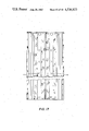
- FIG. 17 is a front view of the base pan of FIG. 3.
- the base pan may be made out of an insulative material such as Noryl, a trademark of General Electric Company.
- insulative material such as Noryl, a trademark of General Electric Company.
- Other kinds of rigid insulative material may be used, and in the preferred embodiment, it is desirable for the rigid insulative material to be one that is easily extrudable and relatively inexpensive.
- the panel board 10 may be mounted in a box 12 when used for home applications or lightindustrial applications.
- the means for, and method of, mounting the base pan into the box will be described in further detail hereinbelow.
- the panel board 10 is an assembly, including an insulative base pan 14, wherein the base pan has a first integral means for engaging a pair of bus bars 16 and 18.
- bus bars 16, 18 are slidably received by the first integral means of the base pan so that the bus bars extend parallel to one another. In this configuration, outwardly extending stabs 19 are in a linear interfaced relationship with one another.
- the bus bars in most applications in the United States will have a voltage differential of 230 volts between each bus bar.
- the base pan 14 further includes a second integral means, for preventing current flow across the base pan between bus bars 16 and 18.
- the second integral means in the preferred embodiment includes a protrusion 20 extending from the base pan having a tortuously formed surface discussed in more detail hereinbelow.
- main-line lugs 22 and 24 are engaged with the base pan 14.
- the mainline lugs 22 and 24 are in direct electrical contact with bus bars 16 and 18.
- electrical leads not shown
- a voltage may be applied directly to bus bars 16 and 18.
- lugs 22 and 24 may be reversed.
- a four-pole, common-trip circuit breaker 28 may be inserted between lugs 22 and 24 and bus bars 16 and 18.
- the slightly different-sized lugs 23 and 25 may be used to connect a two-pole, common-trip circuit breaker 26 to bus bars 16 and 18.
- Panel board 10 further includes a pair of neutral connector elements 30 and 32 engaged with the base pan 14.
- a single-pole circuit breaker 34 may be mounted on the base pan 14 and bus bar 16 or 18 through stab 19. Each single-pole circuit breaker 34 is electrically connected to neutral connector element 30 or 32.
- neutral connector elements 30 and 32 are electrically joined by neutral bar 36 so that a single neutral lead (not shown) attached to neutral lug 38 may provide a neutral connection for all single-pole circuit breakers used in the panel board 10.
- the base pan 14 may be symmetrically formed by an extrusion process.
- a centrally disposed rail 40 may be provided for use as the integral means for preventing current flow across the base pan between the bus bars, including a protrusion extending from the base pan having a tortuously formed surface.
- the tortuously formed surface of the protrusion 20 or rail 40 may be in the form of an inverted-T opening 42 extending through the length of the rail 40.
- the configuration of the preferred embodiment is particularly desirable because the inverted-T opening 42 creates a greatly increased electrical path across the insulative base pan between any two bus bars, yet the inverted-T opening is a relatively simple configuration to extrude.
- the inverted-T opening 42 is also particularly desirable because it creates a pair of outer lips 44 and 46 on which a line shield 48, FIG. 1, may be slidably mounted thereon.
- the first integral means is a protusion 20 extending from the base pan and has a rail 40 and the second integral means thereon.
- the second integral means has a tortuously formed surface in the shape of an inverted "T" opening extending throughout the rail 40 and lips 44 and 46 on the underside of the rail. The lips are for slidably engaging bus bars 16 and 18 and line shield 48. The tortuously formed surface and the lips prevent current flow across the base pan between the bus bars.
- the line shield includes a first singular portion 50 and a second bifurcated portion 52.
- Each section of the second bifurcated portion 52 includes a first leg portion 54, a knee portion 56 and a second leg portion 58. At the base of each leg portion 58 extends an angular inwardly extending foot 60.
- the second bifurcated portion 52 surrounds a length of the centrally disposed rail 40 of the preferred embodiment when slidably engaged with the base pan 14 of FIG. 1 or FIG. 2.
- each angular inwardly extending foot 60 prevents the line shield 48 from being disengaged from the base pan 14 other than by sliding the line shield along the length of the inner rail. As illustrated in FIG. 1 and FIG. 2, the line shield creates a physical barrier between lugs 22, 24 or 23, 25 to prevent accidental contact between both lugs during servicing.
- protrusion 20 also serves to slidably engage arm portions 63 of bus bars 16 and 18 and align the bus bars in a parallel configuration as illustrated in FIGS. 1 and 2.
- the base pan 14 of the preferred embodiment is further provided with a means integral to the base pan for engaging at least one main-line lug.
- This engagement means may include a first pair of channels 64 for slidably engaging a pair of main-line lugs.
- Each channel may be disposed in a parallel relationship on either side of the centrally disposed rail 40 so that appropriately designed main-line lugs may be slidably engaged on either side of the centrally disposed rail.
- Each channel may include a first and second hook portion 66 and 68, respectively.
- each main-line lug is provided with two oppositely disposed ledges 70 and 72 (FIG. 9) for slidable engagement with first and second hook formations 66 and 68 (FIG. 3).
- the base pan is further provided with a pair of double hook formations 80 for supporting the end of a circuit breaker 34 adjacent to neutral connector elements 30, 32.
- the preferred embodiment of the base pan 14, as illustrated in FIG. 3, further includes a second pair of channels 82 for slidably engaging a pair of neutral connector elements.
- the neutral connector elements are described in detail in U.S. Ser. No. 104,101, filed Dec. 17, 1979.
- the panel board assembly further includes a pair of end pieces 84 and 86 slidably engaged in the second pair of channels 82 by respective engagement protrusions 88 and 90.
- a detailed view of end piece 84 is shown in FIG. 5.
- Each end piece 84, 86 further includes a second pair of engagement protrusions 92 and 94 not visible in FIGS. 2 or 3, but which slidably engage base pan 14 under the base pan 14 at connection points 96 and 98, FIG. 2.
- end piece 84 is further provided with a keying arrangement 100, including two outwardly extending notched protrusions 102 and 104.
- keying arrangement 100 including two outwardly extending notched protrusions 102 and 104.
- engagement protrusions 88 and 90 are provided with rectangular clips 108 and 110 while the second pair of engagement protrusions 92 and 94 and the outwardly extending notched protrusions 102 and 104 are provided with circular orifices 112-115.
- the combination of rectangular clips and circular orifices are particularly advantageous in that the rectangular clips provide leeway in attaching each end piece 84, 86 to the base pan 14 without requiring additional attachment hardware, while the circular orifices enhance alignment of each end piece to the base pan.
- FIG. 6 is an end view of the end piece 86, the relative position of engagement protrusions 88, 90, the second pair of engagement protrusions 92, 94, and the outwardly extending notched protrusions 102, 104 are more readily discernible.
- engagement protrusions 88 and 90 include a pair of outwardly extending rectangular ledges 116 and 118, respectively.
- Each end piece 86 is further provided with a pair of guide-wire posts 120 which extend normally outward from the base pan when the end pieces are assembled to the base pan. Each guide-wire post serves to reduce tangling of wires within the circuit breaker box.
- Main-line lug 22 includes a pair of ribs 122 and 124.
- An opening 126 provides a means for passing a main-line wire (not shown) therethrough and for electrically connecting the mainline lug to either a bus bar or a circuit breaker.
- lug 22 is provided with a threaded passageway 128 for engagement with an electrical connection screw 129 illustrated in FIG. 1.
- the electrical connection screw provides a means for enhancing electrical contact between the main-line wire and either a circuit breaker or a bus bar.
- opening 126 of lug 22 further includes a second perpendicularly extending passageway 130 for receiving the main-line wire and either a bus bar or circuit breaker electrical connection.
- the second passageway 130 includes a rectangular extension 132 through which the bus bar or electrical connection of a circuit breaker passes.
- the lug 22 is further provided with a keyhole 134 for engagement with the keying arrangement 100 when lug 22 is used to engage a circuit breaker as illustrated in FIG. 13.
- each lug 22 and 24 of FIG. 13 are mirror images of each other so that when they are interchanged, the outwardly extending notched protrusions 102 and 104 of the keying arrangement as illustrated in FIG. 5 will not engage keyhole 134 (FIG. 10) as illustrated in FIG. 1. In this manner, lugs 22 and 24 can be used to directly engage bus bars 16 and 18.
- circuit breaker 28 (FIG. 13) in between bus bars 16, 18, and lugs 22, 24.
- all that is required is to interchange lugs 22 and 24 as illustrated in FIG. 13 and to attach load straps 136 and 138 to bus bars 16 and 18.
- the keyhole of lugs 22 and 24 completely encases the key or outwardly extending notched protrusion from keying arrangement 100.
- a slightly longer base pan is required to contain the same number of circuit breakers.
- slightly different-sized load straps 140 and 142 are used to engage the two-pole circuit breaker 144; the difference between the load straps for two-pole and four-pole circuit breakers being that a four-pole circuit breaker load strap has an additional extension 145 as can be seen in FIG. 13.
- the load strap 140 may be made out of 3/16th aluminum with a tin plate finish.
- the load strap may include a first strap portion 146 for locating in juxtaposition to a bus bar.
- the first strap portion may include an orifice 148 for attachment to the bus bar.
- Strap 140 further includes a second strap portion 150 (FIG. 12) having a section extending perpendicularly to the first strap portion 146.
- the load strap 140 has a third strap portion 152 extending from the second strap portion 150 in a direction generally parallel to the first strap portion 146.
- the third strap portion includes an indented section 154 on the underside thereof, including a pair of notches 156 and 158 therein, for connection with a circuit breaker as illustrated in FIG. 14.
- the base pan is designed to slidably engage bus bars 16 and 18 FIG. 1. After the bus bars are engaged in the desired location, the base pan-bus bar assembly can be easily mounted inside a circuit breaker box at attachment points 160 and 162 as illustrated in FIG. 1. Snap-in, bus-bar fasteners 164 of the type illustrated in FIGS. 15 and 16 may be used for this purpose. As can be seen in FIG. 16, the bus-bar fastener 164 includes an upper-cross section 170 for simple snap-in installation. The fastener is further provided with circular ribs 172 extending outwardly along the axis of the fastener. And finally, an end cap 174 maintains the fastener on the outer side of the circuit breaker box.
- a plurality of variously shaped orifices may be provided in the base pan for fastening purposes.
- the use of square orifices 176 and 178 is particularly desirable for use in conjunction with fasteners of the type illustrated in FIGS. 15 and 16.
- the combination of the upper-cross section 170 of each fastener together with the square orifice 176 or 178 provides simple alignment of the base pan and fastener with respect to a circuit breaker box.
Landscapes
- Engineering & Computer Science (AREA)
- Power Engineering (AREA)
- Breakers (AREA)
- Distribution Board (AREA)
Abstract
Description
Claims (12)
Priority Applications (2)
| Application Number | Priority Date | Filing Date | Title |
|---|---|---|---|
| US06/315,565 US4536823A (en) | 1981-10-27 | 1981-10-27 | Electric panel board having an improved extruded base pan configuration |
| CA000410464A CA1201196A (en) | 1981-10-27 | 1982-08-31 | Electric panel board having an improved extruded base pan configuration |
Applications Claiming Priority (1)
| Application Number | Priority Date | Filing Date | Title |
|---|---|---|---|
| US06/315,565 US4536823A (en) | 1981-10-27 | 1981-10-27 | Electric panel board having an improved extruded base pan configuration |
Publications (1)
| Publication Number | Publication Date |
|---|---|
| US4536823A true US4536823A (en) | 1985-08-20 |
Family
ID=23225016
Family Applications (1)
| Application Number | Title | Priority Date | Filing Date |
|---|---|---|---|
| US06/315,565 Expired - Lifetime US4536823A (en) | 1981-10-27 | 1981-10-27 | Electric panel board having an improved extruded base pan configuration |
Country Status (2)
| Country | Link |
|---|---|
| US (1) | US4536823A (en) |
| CA (1) | CA1201196A (en) |
Cited By (32)
| Publication number | Priority date | Publication date | Assignee | Title |
|---|---|---|---|---|
| US4667269A (en) * | 1985-11-27 | 1987-05-19 | General Electric Company | Circuit breaker support saddle having a split neutral connector |
| US4672508A (en) * | 1984-05-02 | 1987-06-09 | Bridges Denis R | Mounting rail |
| US4733329A (en) * | 1986-10-31 | 1988-03-22 | Siemens Energy & Automation | Three-phase load center |
| US4740865A (en) * | 1986-10-31 | 1988-04-26 | Siemens Energy & Automation, Inc. | Extruded three-phase base pan configuration for a load center |
| US4785377A (en) * | 1988-03-25 | 1988-11-15 | Siemens Energy & Automation, Inc. | Insulated neutral tie strap |
| US4962443A (en) * | 1988-01-14 | 1990-10-09 | Square D Company | Improved residential loadcenter |
| US5081560A (en) * | 1990-09-27 | 1992-01-14 | Siemens Energy & Automation, Inc. | Load center enclosure |
| US5145415A (en) * | 1991-03-18 | 1992-09-08 | Siemens Electric Limited | Load base with integral wire lug and wire lug retainer |
| US5204803A (en) * | 1991-12-19 | 1993-04-20 | Westinghouse Electric Corp. | Neutral system for electric distribution panelboard |
| US5269710A (en) * | 1990-12-17 | 1993-12-14 | Siemens Energy & Automation, Inc. | Lay-in lug |
| US5341273A (en) * | 1989-07-19 | 1994-08-23 | Square D Company | Electrical load center |
| US5343356A (en) * | 1992-12-31 | 1994-08-30 | Siemens Energy & Automation, Inc. | Panelboard |
| US5351165A (en) * | 1992-12-31 | 1994-09-27 | Siemens Energy & Automation, Inc. | Main circuit breaker or other circuit protective device connector installation kit for panelboards |
| US5450282A (en) * | 1994-05-09 | 1995-09-12 | General Electric Company | Circuit breaker support saddle for automated assembly |
| US5628534A (en) * | 1996-03-27 | 1997-05-13 | Siemens Energy & Automation, Inc. | Door and door latch for an electric load center |
| US5696664A (en) * | 1996-03-27 | 1997-12-09 | Siemens Energy & Automation, Inc. | Basepan with integrally formed posts for mounting components by heat staking |
| US5721667A (en) * | 1996-03-27 | 1998-02-24 | Siemens Energy & Automation, Inc. | Load center interior attachment |
| US5784250A (en) * | 1996-03-27 | 1998-07-21 | Siemens Energy & Automation, Inc. | Neutral bar wire guide |
| US5786982A (en) * | 1996-03-27 | 1998-07-28 | Siemens Energy & Automation, Inc. | Serpentine molded bus bar barrier |
| US5805414A (en) * | 1996-03-27 | 1998-09-08 | Siemens Energy & Automation, Inc. | Neutral tie bar |
| US5835341A (en) * | 1996-03-27 | 1998-11-10 | Siemens Energy & Automation, Inc. | Visible neutral bar |
| US5969937A (en) * | 1996-03-27 | 1999-10-19 | Siemens Energy & Automation, Inc. | Snap-on basepan system |
| US6160698A (en) * | 1998-12-23 | 2000-12-12 | L. L. Culmat, Ltd. | Fasteners for electric load center basepan |
| US6349466B1 (en) * | 1999-10-28 | 2002-02-26 | Siemens Energy & Automation, Inc. | Ready to wire terminal assembly with vibration resistant clamping screws |
| US6459570B1 (en) * | 1997-04-15 | 2002-10-01 | Square D Company | Load center interior panel with snap-in neutral |
| US20080003850A1 (en) * | 2006-06-28 | 2008-01-03 | Eaton Corporation | Modular bus assembly for a loadcenter |
| US20100238611A1 (en) * | 2009-03-23 | 2010-09-23 | Siemens Industry, Inc. | Low-profile electronic circuit breakers, breaker tripping mechanisms, and systems and methods of using same |
| US20110149483A1 (en) * | 2009-12-17 | 2011-06-23 | Schneider Electric USA, Inc. | Panelboard having a parallel feeder bars distribution |
| US20130188297A1 (en) * | 2012-01-24 | 2013-07-25 | Michael J. Ranta | Neutral bus for a neutral bar and electrical distribution panel including the same |
| CN105940579A (en) * | 2014-02-06 | 2016-09-14 | 施耐德电气美国股份有限公司 | Hybrid neutral plug on bar with distributed pitch |
| WO2017214347A1 (en) * | 2016-06-08 | 2017-12-14 | Leviton Manufacturing Co., Inc. | Snap fit circuit breaker and load center system |
| US11799272B2 (en) | 2019-12-13 | 2023-10-24 | Eaton Intelligent Power Limited | Dual contactor electrical panelboard assembly, systems and methods |
Citations (11)
| Publication number | Priority date | Publication date | Assignee | Title |
|---|---|---|---|---|
| US3349292A (en) * | 1966-06-01 | 1967-10-24 | Ite Circuit Breaker Ltd | Load center |
| US3375411A (en) * | 1967-07-03 | 1968-03-26 | Gen Electric | Electrical circuit control device panel board with novel insulating means |
| US3588620A (en) * | 1969-08-06 | 1971-06-28 | Gen Electric | Electrical control device panel assembly with multifunctional insulating support means |
| US4002388A (en) * | 1975-11-20 | 1977-01-11 | I-T-E Imperial Corporation | Stab arrangement for busbars |
| CA1010545A (en) * | 1973-09-27 | 1977-05-17 | William F. Olashaw | Switchboard with improved horizontal busbar mounting provisions |
| US4118754A (en) * | 1977-02-28 | 1978-10-03 | Gould Inc. | Electrical panel having molded base pan |
| US4137424A (en) * | 1976-04-26 | 1979-01-30 | Staff Kg | Rail for supporting electrical fixtures |
| US4167768A (en) * | 1977-11-03 | 1979-09-11 | Square D Company | Single phase electrical panelboard |
| US4167769A (en) * | 1978-06-29 | 1979-09-11 | Gould Inc. | Panelboard having distributed neutral |
| US4231633A (en) * | 1978-09-26 | 1980-11-04 | Gould Inc. | Neutral bar, lug and barrier assembly |
| US4251851A (en) * | 1978-09-18 | 1981-02-17 | Square D Company | Panelboard assembly |
-
1981
- 1981-10-27 US US06/315,565 patent/US4536823A/en not_active Expired - Lifetime
-
1982
- 1982-08-31 CA CA000410464A patent/CA1201196A/en not_active Expired
Patent Citations (13)
| Publication number | Priority date | Publication date | Assignee | Title |
|---|---|---|---|---|
| US3349292A (en) * | 1966-06-01 | 1967-10-24 | Ite Circuit Breaker Ltd | Load center |
| US3375411A (en) * | 1967-07-03 | 1968-03-26 | Gen Electric | Electrical circuit control device panel board with novel insulating means |
| US3588620A (en) * | 1969-08-06 | 1971-06-28 | Gen Electric | Electrical control device panel assembly with multifunctional insulating support means |
| CA1010545A (en) * | 1973-09-27 | 1977-05-17 | William F. Olashaw | Switchboard with improved horizontal busbar mounting provisions |
| US4002388A (en) * | 1975-11-20 | 1977-01-11 | I-T-E Imperial Corporation | Stab arrangement for busbars |
| US4137424A (en) * | 1976-04-26 | 1979-01-30 | Staff Kg | Rail for supporting electrical fixtures |
| US4118754A (en) * | 1977-02-28 | 1978-10-03 | Gould Inc. | Electrical panel having molded base pan |
| US4118754B1 (en) * | 1977-02-28 | 1991-05-21 | Siemens Allis Inc | |
| US4167768A (en) * | 1977-11-03 | 1979-09-11 | Square D Company | Single phase electrical panelboard |
| US4167769A (en) * | 1978-06-29 | 1979-09-11 | Gould Inc. | Panelboard having distributed neutral |
| US4167769B1 (en) * | 1978-06-29 | 1991-11-26 | Siemens Allis Inc | |
| US4251851A (en) * | 1978-09-18 | 1981-02-17 | Square D Company | Panelboard assembly |
| US4231633A (en) * | 1978-09-26 | 1980-11-04 | Gould Inc. | Neutral bar, lug and barrier assembly |
Cited By (47)
| Publication number | Priority date | Publication date | Assignee | Title |
|---|---|---|---|---|
| US4672508A (en) * | 1984-05-02 | 1987-06-09 | Bridges Denis R | Mounting rail |
| US4667269A (en) * | 1985-11-27 | 1987-05-19 | General Electric Company | Circuit breaker support saddle having a split neutral connector |
| US4733329A (en) * | 1986-10-31 | 1988-03-22 | Siemens Energy & Automation | Three-phase load center |
| US4740865A (en) * | 1986-10-31 | 1988-04-26 | Siemens Energy & Automation, Inc. | Extruded three-phase base pan configuration for a load center |
| US4962443A (en) * | 1988-01-14 | 1990-10-09 | Square D Company | Improved residential loadcenter |
| US4785377A (en) * | 1988-03-25 | 1988-11-15 | Siemens Energy & Automation, Inc. | Insulated neutral tie strap |
| US5341273A (en) * | 1989-07-19 | 1994-08-23 | Square D Company | Electrical load center |
| US5081560A (en) * | 1990-09-27 | 1992-01-14 | Siemens Energy & Automation, Inc. | Load center enclosure |
| US5269710A (en) * | 1990-12-17 | 1993-12-14 | Siemens Energy & Automation, Inc. | Lay-in lug |
| US5145415A (en) * | 1991-03-18 | 1992-09-08 | Siemens Electric Limited | Load base with integral wire lug and wire lug retainer |
| US5204803A (en) * | 1991-12-19 | 1993-04-20 | Westinghouse Electric Corp. | Neutral system for electric distribution panelboard |
| US5351165A (en) * | 1992-12-31 | 1994-09-27 | Siemens Energy & Automation, Inc. | Main circuit breaker or other circuit protective device connector installation kit for panelboards |
| US5343356A (en) * | 1992-12-31 | 1994-08-30 | Siemens Energy & Automation, Inc. | Panelboard |
| US5450282A (en) * | 1994-05-09 | 1995-09-12 | General Electric Company | Circuit breaker support saddle for automated assembly |
| US5628534A (en) * | 1996-03-27 | 1997-05-13 | Siemens Energy & Automation, Inc. | Door and door latch for an electric load center |
| US5696664A (en) * | 1996-03-27 | 1997-12-09 | Siemens Energy & Automation, Inc. | Basepan with integrally formed posts for mounting components by heat staking |
| US5721667A (en) * | 1996-03-27 | 1998-02-24 | Siemens Energy & Automation, Inc. | Load center interior attachment |
| US5784250A (en) * | 1996-03-27 | 1998-07-21 | Siemens Energy & Automation, Inc. | Neutral bar wire guide |
| US5786982A (en) * | 1996-03-27 | 1998-07-28 | Siemens Energy & Automation, Inc. | Serpentine molded bus bar barrier |
| US5805414A (en) * | 1996-03-27 | 1998-09-08 | Siemens Energy & Automation, Inc. | Neutral tie bar |
| US5835341A (en) * | 1996-03-27 | 1998-11-10 | Siemens Energy & Automation, Inc. | Visible neutral bar |
| US5969937A (en) * | 1996-03-27 | 1999-10-19 | Siemens Energy & Automation, Inc. | Snap-on basepan system |
| US6266232B1 (en) | 1996-03-27 | 2001-07-24 | Siemens Energy & Automation, Inc. | Snap-on basepan system |
| US6459570B1 (en) * | 1997-04-15 | 2002-10-01 | Square D Company | Load center interior panel with snap-in neutral |
| US6160698A (en) * | 1998-12-23 | 2000-12-12 | L. L. Culmat, Ltd. | Fasteners for electric load center basepan |
| DE10048554B4 (en) * | 1999-10-28 | 2005-12-08 | Siemens Energy & Automation, Inc. | clamping screw |
| US6349466B1 (en) * | 1999-10-28 | 2002-02-26 | Siemens Energy & Automation, Inc. | Ready to wire terminal assembly with vibration resistant clamping screws |
| US20080003850A1 (en) * | 2006-06-28 | 2008-01-03 | Eaton Corporation | Modular bus assembly for a loadcenter |
| US7520759B2 (en) * | 2006-06-28 | 2009-04-21 | Eaton Corporation | Modular bus assembly for a loadcenter |
| AU2007263562B2 (en) * | 2006-06-28 | 2010-07-15 | Eaton Corporation | Modular bus assembly for a loadcenter |
| US9601295B2 (en) | 2009-03-23 | 2017-03-21 | Siemens Industry, Inc. | Breaker tripping mechanisms, circuit breakers, systems, and methods of using same |
| US20100238611A1 (en) * | 2009-03-23 | 2010-09-23 | Siemens Industry, Inc. | Low-profile electronic circuit breakers, breaker tripping mechanisms, and systems and methods of using same |
| US9349559B2 (en) | 2009-03-23 | 2016-05-24 | Siemens Industry, Inc. | Low-profile electronic circuit breakers, breaker tripping mechanisms, and systems and methods of using same |
| US20110149483A1 (en) * | 2009-12-17 | 2011-06-23 | Schneider Electric USA, Inc. | Panelboard having a parallel feeder bars distribution |
| US8547684B2 (en) | 2009-12-17 | 2013-10-01 | Schneider Electric USA, Inc. | Panelboard having a parallel feeder bars distribution |
| US20130188297A1 (en) * | 2012-01-24 | 2013-07-25 | Michael J. Ranta | Neutral bus for a neutral bar and electrical distribution panel including the same |
| CN105940579A (en) * | 2014-02-06 | 2016-09-14 | 施耐德电气美国股份有限公司 | Hybrid neutral plug on bar with distributed pitch |
| US20170033523A1 (en) * | 2014-02-06 | 2017-02-02 | Schneider Electric USA, Inc. | Hybrid neutral plug on bar with distributed pitch |
| US9948043B2 (en) * | 2014-02-06 | 2018-04-17 | Schneider Electric USA, Inc. | Hybrid neutral plug on bar with distributed pitch |
| US20180212380A1 (en) * | 2014-02-06 | 2018-07-26 | Schneider Electric USA, Inc. | Hybrid neutral plug on bar with distributed pitch |
| US10439341B2 (en) * | 2014-02-06 | 2019-10-08 | Schneider Electric USA, Inc. | Hybrid neutral plug on bar with distributed pitch |
| WO2017214347A1 (en) * | 2016-06-08 | 2017-12-14 | Leviton Manufacturing Co., Inc. | Snap fit circuit breaker and load center system |
| US10262826B2 (en) | 2016-06-08 | 2019-04-16 | Leviton Manufacturing Co., Inc. | Snap fit circuit breaker and load center system |
| US10658142B2 (en) | 2016-06-08 | 2020-05-19 | Leviton Manufacturing Co., Inc. | Snap fit circuit breaker and load center system |
| US10971319B2 (en) | 2016-06-08 | 2021-04-06 | Leviton Manufacturing Co., Inc. | Snap fit circuit breaker and load center system |
| US11887798B2 (en) | 2016-06-08 | 2024-01-30 | Leviton Manufacturing Co., Inc. | Snap fit circuit breaker and load center system |
| US11799272B2 (en) | 2019-12-13 | 2023-10-24 | Eaton Intelligent Power Limited | Dual contactor electrical panelboard assembly, systems and methods |
Also Published As
| Publication number | Publication date |
|---|---|
| CA1201196A (en) | 1986-02-25 |
Similar Documents
| Publication | Publication Date | Title |
|---|---|---|
| US4536823A (en) | Electric panel board having an improved extruded base pan configuration | |
| US4073563A (en) | Structure for electrical connections and panel assembly | |
| US5064384A (en) | Jumper assembly for multiple breaker application | |
| US4705334A (en) | Electrical distribution system having an improved splice joint between busway sections | |
| US5488337A (en) | Circuit breaker with distribution lug terminal having trapped insulator | |
| US5745337A (en) | Wire barrier for electrical panel board | |
| US3335330A (en) | Mounting pan assembly for electrical panelboard | |
| FI943780A0 (en) | Device for supplying electrical energy to at least one electrical installation device | |
| US4093970A (en) | Main lug assembly for circuit breaker load centers | |
| US4159504A (en) | Site assembled electrical load center | |
| US8092237B2 (en) | Electrical connection bar and adapted connection device | |
| US5519175A (en) | Electrical distribution equipment | |
| US4269470A (en) | Modular electrical terminal board | |
| US5189596A (en) | Transition for electrical apparatus | |
| US6220901B1 (en) | Electric motor terminal board assembly | |
| US6570769B1 (en) | Electrical appliance with two identically built casing shells | |
| US4536046A (en) | Pull out fusible switches | |
| KR100543964B1 (en) | Bus booth bar and charity booth with connecting method and side coupling structure | |
| US5875093A (en) | Electrical distribution panel interior base assembly | |
| US4679120A (en) | Lighting circuit breaker panelboard modular assembly including circuit breaker indicating clips | |
| CA2134053C (en) | Meter socket pan and assembly | |
| US4311353A (en) | Switchgear bus and connection structure | |
| CA2062821C (en) | Plug element for electric connection, in particular distribution boards or the like | |
| US4492419A (en) | Electric distribution center | |
| KR970003742Y1 (en) | Terminal cover of circuit breaker |
Legal Events
| Date | Code | Title | Description |
|---|---|---|---|
| AS | Assignment |
Owner name: GOULD INC., A CORP. OF DE. Free format text: ASSIGNMENT OF ASSIGNORS INTEREST.;ASSIGNORS:COLEMAN, THOMAS E.;INGRAM, WAYNE A.;JOHNSON, STEPHEN L.;REEL/FRAME:003942/0868 Effective date: 19811021 Owner name: GOULD INC., A CORP. OF, DELAWARE Free format text: ASSIGNMENT OF ASSIGNORS INTEREST;ASSIGNORS:COLEMAN, THOMAS E.;INGRAM, WAYNE A.;JOHNSON, STEPHEN L.;REEL/FRAME:003942/0868 Effective date: 19811021 |
|
| AS | Assignment |
Owner name: SIEMENS-ALLIS, INC., A DE CORP. Free format text: ASSIGNMENT OF ASSIGNORS INTEREST.;ASSIGNORS:GOULD, INC., A DE CORP.;ITE INDUSTRIES, LIMITED, A FEDERAL CORP. OF CANADA;REEL/FRAME:004226/0657 Effective date: 19830131 |
|
| STCF | Information on status: patent grant |
Free format text: PATENTED CASE |
|
| FEPP | Fee payment procedure |
Free format text: PAYOR NUMBER ASSIGNED (ORIGINAL EVENT CODE: ASPN); ENTITY STATUS OF PATENT OWNER: LARGE ENTITY |
|
| FPAY | Fee payment |
Year of fee payment: 4 |
|
| FPAY | Fee payment |
Year of fee payment: 8 |
|
| FPAY | Fee payment |
Year of fee payment: 12 |