US4535239A - Method and apparatus for remote measurement of a particulate matter on a moving sheet - Google Patents
Method and apparatus for remote measurement of a particulate matter on a moving sheet Download PDFInfo
- Publication number
- US4535239A US4535239A US06/500,675 US50067583A US4535239A US 4535239 A US4535239 A US 4535239A US 50067583 A US50067583 A US 50067583A US 4535239 A US4535239 A US 4535239A
- Authority
- US
- United States
- Prior art keywords
- sheet
- infrared energy
- energy
- particulate matter
- angle
- Prior art date
- Legal status (The legal status is an assumption and is not a legal conclusion. Google has not performed a legal analysis and makes no representation as to the accuracy of the status listed.)
- Expired - Fee Related
Links
- 239000013618 particulate matter Substances 0.000 title claims abstract description 22
- 238000000034 method Methods 0.000 title claims abstract description 13
- 238000005259 measurement Methods 0.000 title abstract description 3
- 238000000576 coating method Methods 0.000 claims abstract description 26
- 239000011248 coating agent Substances 0.000 claims abstract description 20
- 239000000758 substrate Substances 0.000 claims abstract description 16
- 239000000463 material Substances 0.000 claims abstract description 12
- 239000011236 particulate material Substances 0.000 claims abstract description 11
- 230000001154 acute effect Effects 0.000 claims abstract description 7
- 239000002245 particle Substances 0.000 claims description 4
- 230000003993 interaction Effects 0.000 claims 1
- 239000000843 powder Substances 0.000 abstract description 3
- 239000004593 Epoxy Substances 0.000 abstract description 2
- 238000001514 detection method Methods 0.000 abstract description 2
- 238000010586 diagram Methods 0.000 description 3
- 238000004519 manufacturing process Methods 0.000 description 3
- 229910052782 aluminium Inorganic materials 0.000 description 2
- XAGFODPZIPBFFR-UHFFFAOYSA-N aluminium Chemical compound [Al] XAGFODPZIPBFFR-UHFFFAOYSA-N 0.000 description 2
- 230000001427 coherent effect Effects 0.000 description 2
- 238000006073 displacement reaction Methods 0.000 description 2
- 238000004924 electrostatic deposition Methods 0.000 description 2
- 229910052751 metal Inorganic materials 0.000 description 2
- 239000002184 metal Substances 0.000 description 2
- 235000013405 beer Nutrition 0.000 description 1
- 235000013361 beverage Nutrition 0.000 description 1
- 235000012174 carbonated soft drink Nutrition 0.000 description 1
- 238000010961 commercial manufacture process Methods 0.000 description 1
- 238000000151 deposition Methods 0.000 description 1
- 230000008021 deposition Effects 0.000 description 1
- 239000003822 epoxy resin Substances 0.000 description 1
- 229920000647 polyepoxide Polymers 0.000 description 1
- 239000011253 protective coating Substances 0.000 description 1
- 239000004065 semiconductor Substances 0.000 description 1
- 229920001187 thermosetting polymer Polymers 0.000 description 1
Images

Classifications
-
- G—PHYSICS
- G01—MEASURING; TESTING
- G01N—INVESTIGATING OR ANALYSING MATERIALS BY DETERMINING THEIR CHEMICAL OR PHYSICAL PROPERTIES
- G01N21/00—Investigating or analysing materials by the use of optical means, i.e. using sub-millimetre waves, infrared, visible or ultraviolet light
- G01N21/17—Systems in which incident light is modified in accordance with the properties of the material investigated
- G01N21/47—Scattering, i.e. diffuse reflection
- G01N21/4738—Diffuse reflection, e.g. also for testing fluids, fibrous materials
-
- G—PHYSICS
- G01—MEASURING; TESTING
- G01N—INVESTIGATING OR ANALYSING MATERIALS BY DETERMINING THEIR CHEMICAL OR PHYSICAL PROPERTIES
- G01N21/00—Investigating or analysing materials by the use of optical means, i.e. using sub-millimetre waves, infrared, visible or ultraviolet light
- G01N21/17—Systems in which incident light is modified in accordance with the properties of the material investigated
- G01N21/25—Colour; Spectral properties, i.e. comparison of effect of material on the light at two or more different wavelengths or wavelength bands
- G01N21/31—Investigating relative effect of material at wavelengths characteristic of specific elements or molecules, e.g. atomic absorption spectrometry
- G01N21/35—Investigating relative effect of material at wavelengths characteristic of specific elements or molecules, e.g. atomic absorption spectrometry using infrared light
- G01N21/3563—Investigating relative effect of material at wavelengths characteristic of specific elements or molecules, e.g. atomic absorption spectrometry using infrared light for analysing solids; Preparation of samples therefor
-
- G—PHYSICS
- G01—MEASURING; TESTING
- G01N—INVESTIGATING OR ANALYSING MATERIALS BY DETERMINING THEIR CHEMICAL OR PHYSICAL PROPERTIES
- G01N21/00—Investigating or analysing materials by the use of optical means, i.e. using sub-millimetre waves, infrared, visible or ultraviolet light
- G01N21/84—Systems specially adapted for particular applications
- G01N21/86—Investigating moving sheets
Definitions
- This invention relates to a method and apparatus to detect and measure the quantity of particulate matter on a substrate, and more particularly to determine the quantity of powdered coating material on the surface of a moving metallic sheet without contacting the sheet or disturbing the coating.
- Strips used to make metal containers and container ends for such beverages as beer, carbonated soft drinks, and the like are given coatings of resinous polymeric materials to form coherent, uniform, and functional coatings as thin as 0.05 mils in thickness.
- Such coatings can be formed from powdered coating materials, such as thermosetting epoxy powders, having average particle sizes in the range of from 1 to 15 microns, and preferably having an average particle size less than 10 microns.
- a preferable method is by the electrostatic deposition of such powdered coating materials.
- the advantages of the preferred electrostatic deposition method are efficiency in the use of the coating materials and the ability to achieve uniformity in very thin coatings.
- This invention solves these problems and provides a method and apparatus for detecting and measuring the quantity of particulate matter on a substrate without contacting the sheet or disturbing the particulate matter.
- the invention employs directed, non-visible light energy and the discovery that the particulate matter on the surface of the sheet will interact with such incident light energy and redirect a portion of such incident light energy at an acute angle that is significantly different from the angle of reflection of such light by the surface of the sheet.
- infrared energy particularly that having a wave length of about 940 nanometers, is particularly effective in such detection and measurement and that a portion of such infrared energy effected by the particulate material may be related to the quantity of particulate material on the substrate.
- non-visible energy such as infrared energy having a wave length of 940 nanometers
- infrared energy having a wave length of 940 nanometers is directed at the surface of the moving sheet so that it impinges on the sheet at an angle of about 45°.
- This detected signal may be converted to a voltage level and amplified and processed with other signals to provide a result that can be interpolated by an anti-log generator to develop a signal proportionate to the weight of particulate material.
- the system for practicing the invention preferably includes a source of infrared energy having a wave length of about 940 nanometers and a detector of infrared energy sensitive to wave lengths of about 940 nanometers.
- the infrared energy source is supported so that its infrared energy impinges upon the moving sheet at an angle of about 45° and the detector is supported so that its energy-receiving surface faces the moving sheet on a line passing through the zone of impingement of the infrared energy and lying normal to the sheet.
- the output of the detector may be amplified to provide a voltage signal logarithmically related to the coating weight and from which the coating weight may be derived by the relationship: ##EQU2## where W is the coating weight in milligrams per square inch per side,
- V R is voltage level in volts
- k 1 and k 2 are constants expressed as voltage signals.
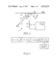
- FIG. 1 is a diagrammatic illustration of a system of this invention
- FIG. 2 is a block diagram of the means used to determine and measure the coating material present on the substrate
- FIG. 3 is a graph showing the relationship between the voltage signal and coating weight of a typical system of the invention.
- FIG. 4 is a diagram of a typical circuit to develop a signal corresponding to coating weight.
- FIG. 1 illustrates a typical system 10 which may be used to practice this invention.
- This system includes a source 12 of non-visible energy, a detector 14 sensitive to the non-visible energy emanating from source 12, and a means 16 for processing the signal from the detector 14 to provide at an indicator 18 an indication of particulate matter present on sheet 20, which is moving from right to left as shown in FIG. 1.
- the energy source 12 which is preferably a source of infrared energy having a wave length 940 nanometers, is positioned by a support (not shown) so that it directs its energy at the coated surface 22 along a line 24 lying at an angle 26 of about 45°.
- the detector 14 has a portion of its surface 14a adapted to receive energy, and the detector 14 is adapted to generate a voltage signal that corresponds to the amount of energy received at surface 14a.
- the detector 14 is positioned in the system so that its energy-receiving surface 14a may accept energy in the direction of a line 28 that is normal to the surface 22 of the moving sheet 20 and that passes through the zone of impingement 30 of the energy source 12 on the coated surface 22.
- infrared energy having a wave length of 940 nanometers is particularly desirable where the particulate matter deposited on the surface of the sheet comprises a clear (i.e., water-like) epoxy resin having an average particle size less than 10 microns.
- the use of such energy which does not lie in the visible range and is not present in any significant quantities in ambient light and other energies generally present in the industrial environments in which such coating material is prepared, permits a system that may be uniformly applied in industry relatively independently of varying conditions from location to location.
- the source 12 can be a Skan-A-Matic Model No. L33107
- the detector 14 can be a Skan-A-Matic Model No. P33101 for such an emitter.
- the detector provides low output for bare metal and the output of the detector increases logarithmically with increasing thickness of particulate matter on the aluminum surface when the emitter and detector are arranged as shown in FIG. 1.
- W p is the density of particulate material on the surface of the substrate in units of weight divided by units of area, for example, grams per inch 2 per side,
- V R is the amplified voltage of the detector 14
- k 1 is a constant corresponding to the displacement 42 of the line 40 from the axis 44 of FIG. 3;
- k 2 is a constant corresponding to the angle 46 of the line 40 with respect to axis 42.
- FIG. 2 is a block diagram of the means to detect and indicate the coating material present on the substrate.
- the system includes the detector 14, amplifier 50, a calibrator 52, and anti-log generator 54, and an indicator 18.
- the detector can be a Scan-A-Matic infrared detector, Model No. P33101.
- the circuits comprising the amplifier 50, calibrator 52, and anti-log generator 54 are shown in FIG. 4.
- the indicator 18 may be a light or alarm signal or, in the preferred embodiment, may be a digital readout or a voltage meter calibrated, for example, in milligrams per square inch.
- the detector 14 which may be a Scan-A-Matic Model P33101 is connected from a voltage source to ground through a resistance 60. Where the Scan-A-Matic P33101 detector is used, it may be connected to 15 volts positive and to a resistance 60 of, typically, 100 ohms.
- Amplifier 50 includes an operational amplifier 61 which may be an Analog Device No. AD524 device or an equivalent instrument amplifier.
- the amplifier is connected between positive and negative voltage sources.
- the sources may be plus and minus 15 volts.
- the amplifier may be provided with an input offset nulling circuit 62 and an output offset nulling circuit 63 with the amplifier gain set to 100.
- the input nulling circuit for example, includes resistors 64 and 65 appropriately connected between the positive voltage source and the amplifier terminals.
- the output nulling circuit 63 includes, for example, resistor 66 and 67 connected between the negative voltage source and the appropriate terminals of amplifier 61.
- resistances 64 and 66 may be, for example, 10,000 ohms and resistances 65 and 67 may be 10,000 ohms potentiometers having the resistors 64 and 66 connected to their slider.
- the output of amplifier 50 is coupled to the calibrator circuit 52.
- the output of amplifier 61 is coupled to a resistance 68 to provide V R input to the calibrator amplifier 71.
- the calibrator 52 includes potentiometer 69 connected between the voltages to which amplifier 61 is connected; and in the preferred circuit, this is plus and minus 15 volts.
- a resistance 70 is connected between the slider of potentiometer 69 and amplifier 71.
- the operational amplifier 71 is used to develop the calibrating signals.
- This calibration amplifier may be a National Semiconductors LM107 device or its equivalent.
- the input signal from amplifier 50 representing V R is connected to the positive input of the operational amplifier and is provided with feedback from the output of the calibrating amplifier 71 through variable resistance 72.
- a variable resistance 73 is connected between ground and the connection between the resistive input 70 to the calibrating amplifier from potentiometer 69.
- resistances 68 and 70 are 300,000 ohms.
- Potentiometer 69 which is connected between plus and minus 15 volts is a 50,000 ohm potentiometer; and variable resistances 72 and 73 have a 200,000 ohm maximum value.
- the output from potentimeter 69 is adjusted to provide a constant voltage signal corresponding to k 1 (the constant corresponding to the displacement 42 of line 40 from axis 44 of FIG. 3).
- the relationship of the resistances of resistor 72 and resistor 68 calibrate the signal corresponding to k 2 (a constant corresponding to the angle 46 of line 40 with respect to axis 42 of FIG. 3), where the values of the resistances 68 and 70 are equal and the value of resistances 72 and 73 are adjusted to be equal.
- the potentiometer 72 and 73 may be ganged to provide for simple adjustment.
- the calibrated signal from calibrator 52 is coupled to an anti-log generator which may be an Intersil No. ICL8049 device or its equivalent; and the output of the anti-log generator 54 drives a display 18 which may analog or digital and calibrated in units of milligrams per square inch per side.
- an anti-log generator which may be an Intersil No. ICL8049 device or its equivalent
- the output of the anti-log generator 54 drives a display 18 which may analog or digital and calibrated in units of milligrams per square inch per side.
Landscapes
- Physics & Mathematics (AREA)
- Health & Medical Sciences (AREA)
- Life Sciences & Earth Sciences (AREA)
- Chemical & Material Sciences (AREA)
- Analytical Chemistry (AREA)
- Biochemistry (AREA)
- General Health & Medical Sciences (AREA)
- General Physics & Mathematics (AREA)
- Immunology (AREA)
- Pathology (AREA)
- Investigating Or Analysing Materials By Optical Means (AREA)
Abstract
Description
Claims (7)
Priority Applications (1)
| Application Number | Priority Date | Filing Date | Title |
|---|---|---|---|
| US06/500,675 US4535239A (en) | 1983-06-03 | 1983-06-03 | Method and apparatus for remote measurement of a particulate matter on a moving sheet |
Applications Claiming Priority (1)
| Application Number | Priority Date | Filing Date | Title |
|---|---|---|---|
| US06/500,675 US4535239A (en) | 1983-06-03 | 1983-06-03 | Method and apparatus for remote measurement of a particulate matter on a moving sheet |
Publications (1)
| Publication Number | Publication Date |
|---|---|
| US4535239A true US4535239A (en) | 1985-08-13 |
Family
ID=23990454
Family Applications (1)
| Application Number | Title | Priority Date | Filing Date |
|---|---|---|---|
| US06/500,675 Expired - Fee Related US4535239A (en) | 1983-06-03 | 1983-06-03 | Method and apparatus for remote measurement of a particulate matter on a moving sheet |
Country Status (1)
| Country | Link |
|---|---|
| US (1) | US4535239A (en) |
Cited By (8)
| Publication number | Priority date | Publication date | Assignee | Title |
|---|---|---|---|---|
| US5104485A (en) * | 1988-05-31 | 1992-04-14 | Hercules Incorporated | Method of measuring non-aqueous constituents in a pulp slurry of a water/cellulose matrix |
| WO1994001528A1 (en) * | 1992-07-13 | 1994-01-20 | Minnesota Mining And Manufacturing Company | A technique to count objects in a scanned image |
| WO1994005770A1 (en) * | 1992-08-27 | 1994-03-17 | Iul, S.A. | Contrast chamber for spotlighting bacterial colonies with respect to the culture medium thereof |
| US5694478A (en) * | 1994-12-15 | 1997-12-02 | Minnesota Mining And Manufacturing Company | Method and apparatus for detecting and identifying microbial colonies |
| US5744322A (en) * | 1993-12-17 | 1998-04-28 | Minnesota Mining And Manufacturing Company | Automated incubating and imaging system for a disposable microorganism culturing device and method of use |
| US20090251710A1 (en) * | 2008-04-04 | 2009-10-08 | Toyota Motor Engineering & Manufacturing North America,Inc. | Method for measuring coating uniformity |
| US20090267623A1 (en) * | 2008-04-23 | 2009-10-29 | Enerize Corporation | Method and automatic system for non-destructive determination physical-chemical properties of powdered materials |
| US20110151501A1 (en) * | 2007-07-09 | 2011-06-23 | Bolea Phillip A | Modular system and method for detecting microorganisms |
Citations (5)
| Publication number | Priority date | Publication date | Assignee | Title |
|---|---|---|---|---|
| US3807868A (en) * | 1971-03-23 | 1974-04-30 | Valmet Oy | Method for determining the fibre orientation in paper or equivalent by the aid of light reflected by the paper |
| US3870884A (en) * | 1973-08-24 | 1975-03-11 | Infra Systems Inc | Apparatus for negating effect of scattered signals upon accuracy of dual-beam infrared measurements |
| US4165939A (en) * | 1975-01-22 | 1979-08-28 | Tsn Company, Inc. | Apparatus for inspection and dimensional measurement by sequential reading |
| US4306151A (en) * | 1978-02-03 | 1981-12-15 | Measurex Corporation | Method of measuring the amount of substance associated with a material in the presence of a contaminant |
| US4421983A (en) * | 1981-03-13 | 1983-12-20 | Champion International Corporation | Method for measuring film thickness on wood panels using an IR analyzer |
-
1983
- 1983-06-03 US US06/500,675 patent/US4535239A/en not_active Expired - Fee Related
Patent Citations (5)
| Publication number | Priority date | Publication date | Assignee | Title |
|---|---|---|---|---|
| US3807868A (en) * | 1971-03-23 | 1974-04-30 | Valmet Oy | Method for determining the fibre orientation in paper or equivalent by the aid of light reflected by the paper |
| US3870884A (en) * | 1973-08-24 | 1975-03-11 | Infra Systems Inc | Apparatus for negating effect of scattered signals upon accuracy of dual-beam infrared measurements |
| US4165939A (en) * | 1975-01-22 | 1979-08-28 | Tsn Company, Inc. | Apparatus for inspection and dimensional measurement by sequential reading |
| US4306151A (en) * | 1978-02-03 | 1981-12-15 | Measurex Corporation | Method of measuring the amount of substance associated with a material in the presence of a contaminant |
| US4421983A (en) * | 1981-03-13 | 1983-12-20 | Champion International Corporation | Method for measuring film thickness on wood panels using an IR analyzer |
Cited By (14)
| Publication number | Priority date | Publication date | Assignee | Title |
|---|---|---|---|---|
| US5104485A (en) * | 1988-05-31 | 1992-04-14 | Hercules Incorporated | Method of measuring non-aqueous constituents in a pulp slurry of a water/cellulose matrix |
| WO1994001528A1 (en) * | 1992-07-13 | 1994-01-20 | Minnesota Mining And Manufacturing Company | A technique to count objects in a scanned image |
| US5403722A (en) * | 1992-07-13 | 1995-04-04 | Minnesota Mining And Manufacturing Company | Technique to count objects in a scanned image |
| WO1994005770A1 (en) * | 1992-08-27 | 1994-03-17 | Iul, S.A. | Contrast chamber for spotlighting bacterial colonies with respect to the culture medium thereof |
| US5545561A (en) * | 1992-08-27 | 1996-08-13 | Iul, S.A. | Contrast chamber for spotlighting bacterial colonies with respect to the culture medium thereof |
| US5744322A (en) * | 1993-12-17 | 1998-04-28 | Minnesota Mining And Manufacturing Company | Automated incubating and imaging system for a disposable microorganism culturing device and method of use |
| US5694478A (en) * | 1994-12-15 | 1997-12-02 | Minnesota Mining And Manufacturing Company | Method and apparatus for detecting and identifying microbial colonies |
| US20110151501A1 (en) * | 2007-07-09 | 2011-06-23 | Bolea Phillip A | Modular system and method for detecting microorganisms |
| US9834748B2 (en) | 2007-07-09 | 2017-12-05 | 3M Innovative Properties Company | Modular system and method for detecting microorganisms |
| US10190089B2 (en) | 2007-07-09 | 2019-01-29 | 3M Innovative Properties Company | Modular system and method for detecting microorganisms |
| US20090251710A1 (en) * | 2008-04-04 | 2009-10-08 | Toyota Motor Engineering & Manufacturing North America,Inc. | Method for measuring coating uniformity |
| US7903265B2 (en) | 2008-04-04 | 2011-03-08 | Toyota Motor Engineering & Manufacturing North America, Inc. | Method for measuring coating uniformity |
| US20090267623A1 (en) * | 2008-04-23 | 2009-10-29 | Enerize Corporation | Method and automatic system for non-destructive determination physical-chemical properties of powdered materials |
| US8309024B2 (en) | 2008-04-23 | 2012-11-13 | Enerize Corporation | Methods and systems for non-destructive determination of fluorination of carbon powders |
Similar Documents
| Publication | Publication Date | Title |
|---|---|---|
| US5539322A (en) | Calibrated microwave dielectric coating thickness gauge | |
| US4695797A (en) | Method of and apparatus for layer thickness measurement | |
| US5914611A (en) | Method and apparatus for measuring sheet resistance and thickness of thin films and substrates | |
| US4277744A (en) | Apparatus for measuring electric and magnetic fields | |
| US3693079A (en) | Apparatus for measuring percent moisture content of particulate material using microwaves and penetrating radiation | |
| US3774238A (en) | Three-terminal capacitive apparatus for remotely responding to a condition or dielectric properties of a material | |
| US4535239A (en) | Method and apparatus for remote measurement of a particulate matter on a moving sheet | |
| US3828190A (en) | Detector assembly | |
| EP0708912B1 (en) | Methods and apparatus for determining a displacement of an object | |
| US4255709A (en) | Device for providing an electrical signal proportional to the thickness of a measured coating with an automatic range switch and sensitivity control | |
| US4977366A (en) | High frequency power sensing device | |
| US4094073A (en) | Angle detector | |
| US4399403A (en) | Microwave moisture measuring, indicating and control apparatus | |
| WO1992019933A1 (en) | Non-contact wet or dry film thickness measuring device using eddy current and ultrasonic sensors | |
| US3636763A (en) | Measurement of the flow of particulate material | |
| WO1991018257A1 (en) | Contact measuring device for determining the dry film thickness of a paint on a plastic substrate | |
| US5393557A (en) | Method for measuring electromagnetic properties | |
| US3716782A (en) | Capacitance gage for measuring small distances | |
| US3870884A (en) | Apparatus for negating effect of scattered signals upon accuracy of dual-beam infrared measurements | |
| GB1185181A (en) | Method and Apparatus for Improving Backscatter Gauge Response | |
| US20030006148A1 (en) | Method and apparatus for measuring accumulated and instant rate of material loss or material gain | |
| US5426373A (en) | Two electrode device for determining electrical properties of a material on a metal substratum | |
| US3409774A (en) | Method of determining the thickness of a coating on a metal base and method of calibrating the thickness gauge | |
| US3781911A (en) | Apparatus for monitoring thickness of evaporated film | |
| JPH06300635A (en) | Radiation measuring instrument |
Legal Events
| Date | Code | Title | Description |
|---|---|---|---|
| AS | Assignment |
Owner name: BALL CORPORATION 345 SOUTH HIGH STREET MUNCIE, IN Free format text: ASSIGNMENT OF ASSIGNORS INTEREST.;ASSIGNOR:BRIGHTON, ANDREW P.;REEL/FRAME:004136/0316 Effective date: 19830531 |
|
| AS | Assignment |
Owner name: BALL CORPORATION, 345 SOUTH HIGH ST., MUNCIE, IN. Free format text: ASSIGNMENT OF ASSIGNORS INTEREST.;ASSIGNOR:BRIGHTON, ANDREW P.;REEL/FRAME:004157/0604 Effective date: 19830728 Owner name: BALL CORPORATION, INDIANA Free format text: ASSIGNMENT OF ASSIGNORS INTEREST;ASSIGNOR:BRIGHTON, ANDREW P.;REEL/FRAME:004157/0604 Effective date: 19830728 |
|
| FEPP | Fee payment procedure |
Free format text: PAYOR NUMBER ASSIGNED (ORIGINAL EVENT CODE: ASPN); ENTITY STATUS OF PATENT OWNER: LARGE ENTITY |
|
| FPAY | Fee payment |
Year of fee payment: 4 |
|
| FPAY | Fee payment |
Year of fee payment: 8 |
|
| REMI | Maintenance fee reminder mailed | ||
| LAPS | Lapse for failure to pay maintenance fees | ||
| FP | Lapsed due to failure to pay maintenance fee |
Effective date: 19970813 |
|
| STCH | Information on status: patent discontinuation |
Free format text: PATENT EXPIRED DUE TO NONPAYMENT OF MAINTENANCE FEES UNDER 37 CFR 1.362 |