US4534407A - Heat exchangers - Google Patents
Heat exchangers Download PDFInfo
- Publication number
- US4534407A US4534407A US06/527,810 US52781083A US4534407A US 4534407 A US4534407 A US 4534407A US 52781083 A US52781083 A US 52781083A US 4534407 A US4534407 A US 4534407A
- Authority
- US
- United States
- Prior art keywords
- clamping members
- tubes
- arms
- matrix
- heat exchanger
- Prior art date
- Legal status (The legal status is an assumption and is not a legal conclusion. Google has not performed a legal analysis and makes no representation as to the accuracy of the status listed.)
- Expired - Fee Related
Links
Images

Classifications
-
- F—MECHANICAL ENGINEERING; LIGHTING; HEATING; WEAPONS; BLASTING
- F28—HEAT EXCHANGE IN GENERAL
- F28F—DETAILS OF HEAT-EXCHANGE AND HEAT-TRANSFER APPARATUS, OF GENERAL APPLICATION
- F28F9/00—Casings; Header boxes; Auxiliary supports for elements; Auxiliary members within casings
- F28F9/001—Casings in the form of plate-like arrangements; Frames enclosing a heat exchange core
-
- F—MECHANICAL ENGINEERING; LIGHTING; HEATING; WEAPONS; BLASTING
- F28—HEAT EXCHANGE IN GENERAL
- F28D—HEAT-EXCHANGE APPARATUS, NOT PROVIDED FOR IN ANOTHER SUBCLASS, IN WHICH THE HEAT-EXCHANGE MEDIA DO NOT COME INTO DIRECT CONTACT
- F28D1/00—Heat-exchange apparatus having stationary conduit assemblies for one heat-exchange medium only, the media being in contact with different sides of the conduit wall, in which the other heat-exchange medium is a large body of fluid, e.g. domestic or motor car radiators
- F28D1/02—Heat-exchange apparatus having stationary conduit assemblies for one heat-exchange medium only, the media being in contact with different sides of the conduit wall, in which the other heat-exchange medium is a large body of fluid, e.g. domestic or motor car radiators with heat-exchange conduits immersed in the body of fluid
- F28D1/04—Heat-exchange apparatus having stationary conduit assemblies for one heat-exchange medium only, the media being in contact with different sides of the conduit wall, in which the other heat-exchange medium is a large body of fluid, e.g. domestic or motor car radiators with heat-exchange conduits immersed in the body of fluid with tubular conduits
- F28D1/053—Heat-exchange apparatus having stationary conduit assemblies for one heat-exchange medium only, the media being in contact with different sides of the conduit wall, in which the other heat-exchange medium is a large body of fluid, e.g. domestic or motor car radiators with heat-exchange conduits immersed in the body of fluid with tubular conduits the conduits being straight
- F28D1/05316—Assemblies of conduits connected to common headers, e.g. core type radiators
-
- F—MECHANICAL ENGINEERING; LIGHTING; HEATING; WEAPONS; BLASTING
- F28—HEAT EXCHANGE IN GENERAL
- F28F—DETAILS OF HEAT-EXCHANGE AND HEAT-TRANSFER APPARATUS, OF GENERAL APPLICATION
- F28F2225/00—Reinforcing means
-
- F—MECHANICAL ENGINEERING; LIGHTING; HEATING; WEAPONS; BLASTING
- F28—HEAT EXCHANGE IN GENERAL
- F28F—DETAILS OF HEAT-EXCHANGE AND HEAT-TRANSFER APPARATUS, OF GENERAL APPLICATION
- F28F2265/00—Safety or protection arrangements; Arrangements for preventing malfunction
- F28F2265/26—Safety or protection arrangements; Arrangements for preventing malfunction for allowing differential expansion between elements
-
- Y—GENERAL TAGGING OF NEW TECHNOLOGICAL DEVELOPMENTS; GENERAL TAGGING OF CROSS-SECTIONAL TECHNOLOGIES SPANNING OVER SEVERAL SECTIONS OF THE IPC; TECHNICAL SUBJECTS COVERED BY FORMER USPC CROSS-REFERENCE ART COLLECTIONS [XRACs] AND DIGESTS
- Y10—TECHNICAL SUBJECTS COVERED BY FORMER USPC
- Y10S—TECHNICAL SUBJECTS COVERED BY FORMER USPC CROSS-REFERENCE ART COLLECTIONS [XRACs] AND DIGESTS
- Y10S165/00—Heat exchange
- Y10S165/051—Heat exchange having expansion and contraction relieving or absorbing means
- Y10S165/052—Heat exchange having expansion and contraction relieving or absorbing means for cylindrical heat exchanger
- Y10S165/053—Flexible or movable header or header element
- Y10S165/054—Movable header, e.g. floating header
- Y10S165/055—Movable header, e.g. floating header including guiding means for movable header
Definitions
- This invention relates to heat exchangers, especially to those suitable for use in vehicle cooling systems.
- Such heat exchangers comprise a pair of header tanks, a plurality of tubes extending between the header tanks and airways located between the tubes, and clamping members parallel to the tubes on each side of the matrix.
- the clamping members serve to resist expansion of the matrix under pressure pulsations in the tubes in use. They are sometimes rigidly connected to the header tanks so that they can perform this function.
- the invention provides a heat exchanger which comprises a pair of header tanks, a plurality of tubes extending between the header tanks and airways located between the tubes, clamping members parallel to the tubes on each side of the matrix, and a pair of arms rigidly connected two ends of each header tank, which arms so engage the clamping members that each clamping member is held in contact with the matrix but each arm can slide relative to the associated clamping member in a direction parallel to the tubes.
- the clamping members can still clamp the matrix together, but the sliding movement ensures that the outer regions of the tube plate are not stressed despite the differential thermal expansion.
- each clamping member is shorter than the tubes.
- Such a clamping member can also hold the matrix together in the typical matrix making machine, which is such that nothing longer than the tubes can be accommodated.
- FIG. 1 is a front view of a first heat exchanger
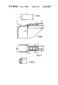
- FIG. 2 is an enlarged view of the heat exchanger taken in the direction of the arrow A;
- FIG. 3 is a section through lines B--B of FIG. 2;
- FIG. 4 is a section through lines C--C of FIG. 2;
- FIG. 5 is a view of the second heat exchanger
- FIG. 6 is an enlarged view showing the expansion joint of the second heat exchanger
- FIG. 7 is a section through the lines d--d of FIG. 6;
- FIG. 8 is a section through the lines e--e of FIG. 7.
- the first heat exchanger comprises a top header tank 1 having an outlet 2 and a bottom header tank 3 having an inlet 4.
- Tubes 5 run between the header tanks and are interspersed with airways 6 consisting of a metal strip in zig-zag form.
- the matrix of tubes and airways is clamped together at the side by means of two clamping members 7.
- Each header tank is closed on the side nearest to the matrix by a plate, called a tube plate, into which the ends of the tubes 5 are soldered.
- a plate called a tube plate
- Each tube plate has an upturned rim.
- the rim for the tube plate for the upper header tank is identified by the reference numeral 8.
- the tubes 5 themselves are flattened in section.
- the tube and airway matrix is assembled between the two clamping members (held together by suitable means, for example, one or more ties of the form described and claimed in our co-pending United Kingdom Patent Application No. 82 20954) in a machine.
- the tubes 5 are pre-coated with solder.
- the matrix including the clamping members 7 is then baked and in this way the tubes are soldered to the airways.
- the tube plates and shells of the header tanks are only fitted in position once this assembly has been built up.
- arms 9 are rivetted to the rim 8 of the upper tube plate, and similar arms are rivetted to the lower tube plate in the same way.
- each arm is of channel section, but has a part with a relatively wide base and shallow sides where it attaches to the tube plate and a part with a narrower base and deeper sides where it engages the clamping member.
- the clamping member is of box section, although the box is not continuous.
- a further advantage is that the clamping members 7, being shorter than the tubes 5, can be accomodated in a conventional matrix forming machine.
- this called for two parts instead of one in accordance with the invention, but also special tooling for the outer part for each shape of radiator.
- the simple clamping member 7 can be rolled and can be cut to any desired length, and tooling costs for the radiator of the present invention are thereby significantly reduced.
- arms 9 may be rivetted to the rim 8 of the tube plates, they may be welded thereto, and the rivetting and welding may if desired be done directly to the remainder of the headed tank.
- the shells of the header tanks are of plastics material. They are closed by tube plates 8 as in the first embodiment.
- the moulding of the shells is extended at the ends into the arms 9 which engage in the clamping members 7 as in the first embodiment.
- this serves to protect the joint of the plastics shell to the tube plate 8, that is, if the shell is inadvertently knocked, the arms 9 take up some of the force rather than all the strain being taken by the shell/tube plate joint.
- the moulding of the header tank and arms can be done in one piece.
- the airways 6 have a projection 10 which engages with the clamping member to locate the clamping member 7 against movement at right-angles to the plane of the radiator. This engagement of the airways and clamping member 7 can be achieved in alternative ways.
Landscapes
- Engineering & Computer Science (AREA)
- Physics & Mathematics (AREA)
- Thermal Sciences (AREA)
- Mechanical Engineering (AREA)
- General Engineering & Computer Science (AREA)
- Heat-Exchange Devices With Radiators And Conduit Assemblies (AREA)
Abstract
Description
Claims (3)
Applications Claiming Priority (4)
| Application Number | Priority Date | Filing Date | Title |
|---|---|---|---|
| GB8225112 | 1982-09-03 | ||
| GB8225112A GB2126702B (en) | 1982-09-03 | 1982-09-03 | Improvements relating to heat exchangers |
| GB8310087 | 1983-04-14 | ||
| GB838310087A GB8310087D0 (en) | 1983-04-14 | 1983-04-14 | Heat exchangers |
Publications (1)
| Publication Number | Publication Date |
|---|---|
| US4534407A true US4534407A (en) | 1985-08-13 |
Family
ID=26283733
Family Applications (1)
| Application Number | Title | Priority Date | Filing Date |
|---|---|---|---|
| US06/527,810 Expired - Fee Related US4534407A (en) | 1982-09-03 | 1983-08-30 | Heat exchangers |
Country Status (2)
| Country | Link |
|---|---|
| US (1) | US4534407A (en) |
| EP (1) | EP0102715A3 (en) |
Cited By (17)
| Publication number | Priority date | Publication date | Assignee | Title |
|---|---|---|---|---|
| US4705104A (en) * | 1984-02-27 | 1987-11-10 | Valeo | Heat exchanger, in particular for a motor vehicle, having a rigid connection between a bundle of tubes and a water box and perforated plate assembly |
| US5186239A (en) * | 1992-01-30 | 1993-02-16 | Ford Motor Company | Heat exchanger with thermal stress relieving zone |
| US5257454A (en) * | 1992-01-30 | 1993-11-02 | Ford Motor Company | Method of making a heat exchanger with thermal stress relieving zone |
| US5323848A (en) * | 1992-04-24 | 1994-06-28 | Valeo Thermique Moteur | Heat exchanger, in particular a vehicle radiator, and a side support structure for such a heat exchanger |
| US5447192A (en) * | 1994-07-12 | 1995-09-05 | Behr Heat Transfer Systems, Inc. | Heat exchanger assembly with reinforcement and method for making same |
| US5630472A (en) * | 1994-10-19 | 1997-05-20 | Valeo Thermique Moteur | Heat exchanger with a bundle of tubes and a metallic tube plate |
| US5931223A (en) * | 1995-04-28 | 1999-08-03 | Ford Motor Company | Heat exchanger with thermal stress relieving zone |
| US5954123A (en) * | 1995-06-12 | 1999-09-21 | Ford Global Technologies, Inc. | Heat exchanger |
| US6006430A (en) * | 1993-09-16 | 1999-12-28 | Nippondenso Co., Ltd. | Aluminum heat exchanger |
| EP0767298B1 (en) * | 1995-10-06 | 2003-07-16 | Valeo Thermique Moteur S.A. | Device for mounting a high temperature heat exchanger |
| US6736197B2 (en) * | 2001-03-23 | 2004-05-18 | Denso Corporation | Heat exchanger |
| US20060213649A1 (en) * | 2005-03-24 | 2006-09-28 | Kroetsch Karl P | Heat exchanger design based on partial strain energy density ratio |
| US20080135208A1 (en) * | 2004-03-17 | 2008-06-12 | Behr Gmbh & Co. Kg | Tubular Heat Exchanger |
| US7395853B2 (en) | 2004-10-01 | 2008-07-08 | Delphi Technologies, Inc. | Heat exchanger assembly for a motor vehicle |
| US20090178781A1 (en) * | 2008-01-15 | 2009-07-16 | Denso International America, Inc. | Spring mounting feature for heat exchanger |
| DE102014219209A1 (en) * | 2014-09-22 | 2016-03-24 | Mahle International Gmbh | Heat exchanger |
| US20200064084A1 (en) * | 2018-08-21 | 2020-02-27 | Denso International America, Inc. | Side Plate End Tab For Heat Exchanger |
Families Citing this family (5)
| Publication number | Priority date | Publication date | Assignee | Title |
|---|---|---|---|---|
| DE3428857A1 (en) * | 1984-08-04 | 1986-02-13 | Süddeutsche Kühlerfabrik Julius Fr. Behr GmbH & Co KG, 7000 Stuttgart | WATER / AIR COOLER FOR WATER-COOLED COMBUSTION ENGINES |
| DE3502619A1 (en) * | 1985-01-26 | 1986-07-31 | Süddeutsche Kühlerfabrik Julius Fr. Behr GmbH & Co KG, 7000 Stuttgart | HEAT EXCHANGER, ESPECIALLY REFRIGERANT EVAPORATOR |
| FR2753528B1 (en) * | 1996-09-19 | 1998-12-04 | Valeo Thermique Moteur Sa | CHEEK LOCK HEAT EXCHANGER, ESPECIALLY FOR A MOTOR VEHICLE |
| ES2186030T3 (en) * | 1997-03-11 | 2003-05-01 | Behr Gmbh & Co | HEAT EXCHANGER FOR A MOTOR VEHICLE. |
| DE19737273A1 (en) * | 1997-08-27 | 1999-03-04 | Behr Gmbh & Co | Heat exchanger with two parallel-running collection tubes |
Citations (12)
| Publication number | Priority date | Publication date | Assignee | Title |
|---|---|---|---|---|
| US1834001A (en) * | 1926-11-19 | 1931-12-01 | Modine Mfg Co | Radiator |
| US2933291A (en) * | 1958-03-14 | 1960-04-19 | Modine Mfg Co | Heat exchanger with an expansion joint |
| US3165151A (en) * | 1962-04-09 | 1965-01-12 | Young Radiator Co | Heat-transfer trussed-radiator |
| FR2036696A1 (en) * | 1969-02-25 | 1970-12-31 | Chausson Usines Sa | |
| US3627035A (en) * | 1970-07-20 | 1971-12-14 | Young Radiator Co | Junction plates for multiple heat exchanger units |
| FR2183374A5 (en) * | 1972-05-04 | 1973-12-14 | Chausson Usines Sa | |
| US3960210A (en) * | 1972-05-04 | 1976-06-01 | Societe Anonyme Des Usines Chausson | Device for fixing tube plates and lateral flanges of heat exchangers |
| GB1443725A (en) * | 1972-08-02 | 1976-07-21 | Chausson Usines Sa | Radiators |
| GB1461638A (en) * | 1973-04-04 | 1977-01-13 | Chausson Usines Sa | Heat exchangers apparatus for making debossed displays in blanks |
| US4137982A (en) * | 1977-08-08 | 1979-02-06 | Caterpillar Tractor Co. | Reinforced radiator mounting for heavy vehicles |
| WO1979000960A1 (en) * | 1978-04-21 | 1979-11-15 | Scm Corp | Process for the manufacture of metal joining paste |
| FR2494828A1 (en) * | 1980-11-24 | 1982-05-28 | Chausson Usines Sa | Finned tube heat exchanger - has interlock securing flanges on tubes and manifolds together |
-
1983
- 1983-07-13 EP EP83304056A patent/EP0102715A3/en not_active Withdrawn
- 1983-08-30 US US06/527,810 patent/US4534407A/en not_active Expired - Fee Related
Patent Citations (12)
| Publication number | Priority date | Publication date | Assignee | Title |
|---|---|---|---|---|
| US1834001A (en) * | 1926-11-19 | 1931-12-01 | Modine Mfg Co | Radiator |
| US2933291A (en) * | 1958-03-14 | 1960-04-19 | Modine Mfg Co | Heat exchanger with an expansion joint |
| US3165151A (en) * | 1962-04-09 | 1965-01-12 | Young Radiator Co | Heat-transfer trussed-radiator |
| FR2036696A1 (en) * | 1969-02-25 | 1970-12-31 | Chausson Usines Sa | |
| US3627035A (en) * | 1970-07-20 | 1971-12-14 | Young Radiator Co | Junction plates for multiple heat exchanger units |
| FR2183374A5 (en) * | 1972-05-04 | 1973-12-14 | Chausson Usines Sa | |
| US3960210A (en) * | 1972-05-04 | 1976-06-01 | Societe Anonyme Des Usines Chausson | Device for fixing tube plates and lateral flanges of heat exchangers |
| GB1443725A (en) * | 1972-08-02 | 1976-07-21 | Chausson Usines Sa | Radiators |
| GB1461638A (en) * | 1973-04-04 | 1977-01-13 | Chausson Usines Sa | Heat exchangers apparatus for making debossed displays in blanks |
| US4137982A (en) * | 1977-08-08 | 1979-02-06 | Caterpillar Tractor Co. | Reinforced radiator mounting for heavy vehicles |
| WO1979000960A1 (en) * | 1978-04-21 | 1979-11-15 | Scm Corp | Process for the manufacture of metal joining paste |
| FR2494828A1 (en) * | 1980-11-24 | 1982-05-28 | Chausson Usines Sa | Finned tube heat exchanger - has interlock securing flanges on tubes and manifolds together |
Cited By (21)
| Publication number | Priority date | Publication date | Assignee | Title |
|---|---|---|---|---|
| US4705104A (en) * | 1984-02-27 | 1987-11-10 | Valeo | Heat exchanger, in particular for a motor vehicle, having a rigid connection between a bundle of tubes and a water box and perforated plate assembly |
| US5186239A (en) * | 1992-01-30 | 1993-02-16 | Ford Motor Company | Heat exchanger with thermal stress relieving zone |
| US5257454A (en) * | 1992-01-30 | 1993-11-02 | Ford Motor Company | Method of making a heat exchanger with thermal stress relieving zone |
| US5323848A (en) * | 1992-04-24 | 1994-06-28 | Valeo Thermique Moteur | Heat exchanger, in particular a vehicle radiator, and a side support structure for such a heat exchanger |
| US6006430A (en) * | 1993-09-16 | 1999-12-28 | Nippondenso Co., Ltd. | Aluminum heat exchanger |
| US5447192A (en) * | 1994-07-12 | 1995-09-05 | Behr Heat Transfer Systems, Inc. | Heat exchanger assembly with reinforcement and method for making same |
| US5630472A (en) * | 1994-10-19 | 1997-05-20 | Valeo Thermique Moteur | Heat exchanger with a bundle of tubes and a metallic tube plate |
| US5931223A (en) * | 1995-04-28 | 1999-08-03 | Ford Motor Company | Heat exchanger with thermal stress relieving zone |
| US5954123A (en) * | 1995-06-12 | 1999-09-21 | Ford Global Technologies, Inc. | Heat exchanger |
| EP0767298B1 (en) * | 1995-10-06 | 2003-07-16 | Valeo Thermique Moteur S.A. | Device for mounting a high temperature heat exchanger |
| US6736197B2 (en) * | 2001-03-23 | 2004-05-18 | Denso Corporation | Heat exchanger |
| US20080135208A1 (en) * | 2004-03-17 | 2008-06-12 | Behr Gmbh & Co. Kg | Tubular Heat Exchanger |
| US7921902B2 (en) * | 2004-03-17 | 2011-04-12 | Behr Gmbh & Co. Kg | Tubular heat exchanger |
| US7395853B2 (en) | 2004-10-01 | 2008-07-08 | Delphi Technologies, Inc. | Heat exchanger assembly for a motor vehicle |
| US20060213649A1 (en) * | 2005-03-24 | 2006-09-28 | Kroetsch Karl P | Heat exchanger design based on partial strain energy density ratio |
| US7207378B2 (en) * | 2005-03-24 | 2007-04-24 | Delphi Technologies, Inc. | Heat exchanger design based on partial stain energy density ratio |
| US20090178781A1 (en) * | 2008-01-15 | 2009-07-16 | Denso International America, Inc. | Spring mounting feature for heat exchanger |
| US8281848B2 (en) * | 2008-01-15 | 2012-10-09 | Denso International America, Inc. | Spring mounting feature for heat exchanger |
| DE102014219209A1 (en) * | 2014-09-22 | 2016-03-24 | Mahle International Gmbh | Heat exchanger |
| US20200064084A1 (en) * | 2018-08-21 | 2020-02-27 | Denso International America, Inc. | Side Plate End Tab For Heat Exchanger |
| US10704842B2 (en) * | 2018-08-21 | 2020-07-07 | Denso International America, Inc. | Side plate end tab for heat exchanger |
Also Published As
| Publication number | Publication date |
|---|---|
| EP0102715A3 (en) | 1984-08-01 |
| EP0102715A2 (en) | 1984-03-14 |
Similar Documents
| Publication | Publication Date | Title |
|---|---|---|
| US4534407A (en) | Heat exchangers | |
| US6311768B1 (en) | Clip on manifold heat exchanger | |
| US5205349A (en) | Heat exchanger bracket mounting structure | |
| US7077192B2 (en) | Manifold with integrated pipe for a heat exchanger | |
| US7143824B2 (en) | Heat exchanger, in particular charge-air cooler | |
| JP3760571B2 (en) | Heat exchanger | |
| US6530424B2 (en) | Clip on manifold heat exchanger | |
| JP2000283689A (en) | Heat exchanger | |
| US4967836A (en) | Heat exchanger and method of making a gasket seal of the heat exhanger | |
| US5704423A (en) | Flat tube for heat exchanger | |
| US8069911B2 (en) | Radiator with built-in oil cooler | |
| US20170198975A1 (en) | Heat Exchanger Construction | |
| US5058662A (en) | Multi tube heat exchanger with integral tube spacers and interlocks | |
| US6332495B1 (en) | Clip on manifold heat exchanger | |
| US4324290A (en) | Heat exchanger comprising a core of tubes engaged inside end plates mechanically connected with header boxes | |
| US4705104A (en) | Heat exchanger, in particular for a motor vehicle, having a rigid connection between a bundle of tubes and a water box and perforated plate assembly | |
| SE539124C2 (en) | Vehicle heat exchanger tubes and vehicle coolers including such tubes and ways of forming a vehicle heat exchanger tubes | |
| GB1590032A (en) | Heat exchangers | |
| US6405788B1 (en) | Device for assembling an affixed component onto a heat exchanger, for a motor vehicle in particular | |
| US6662863B2 (en) | Structure of heat exchanger tank | |
| GB2138335A (en) | An assembly of two parts | |
| WO2021049505A1 (en) | Tank structure of heat exchanger | |
| US20070012425A1 (en) | Heat exchanger | |
| US4332068A (en) | Heat exchanger assembly | |
| GB2126702A (en) | Improvements relating to heat exchangers |
Legal Events
| Date | Code | Title | Description |
|---|---|---|---|
| AS | Assignment |
Owner name: UNIPART GROUP LIMITED, UNIPART HOUSE, GARSINGTON R Free format text: ASSIGNMENT OF ASSIGNORS INTEREST.;ASSIGNOR:LARDNER, GRAHAM G.;REEL/FRAME:004193/0991 Effective date: 19831025 Owner name: UNIPART GROUP LIMITED, UNITED KINGDOM Free format text: ASSIGNMENT OF ASSIGNORS INTEREST;ASSIGNOR:LARDNER, GRAHAM G.;REEL/FRAME:004193/0991 Effective date: 19831025 |
|
| REMI | Maintenance fee reminder mailed | ||
| LAPS | Lapse for failure to pay maintenance fees | ||
| STCH | Information on status: patent discontinuation |
Free format text: PATENT EXPIRED DUE TO NONPAYMENT OF MAINTENANCE FEES UNDER 37 CFR 1.362 |
|
| FP | Lapsed due to failure to pay maintenance fee |
Effective date: 19890813 |
|
| LAPS | Lapse for failure to pay maintenance fees |
Free format text: PATENT EXPIRED FOR FAILURE TO PAY MAINTENANCE FEES (ORIGINAL EVENT CODE: EXP.); ENTITY STATUS OF PATENT OWNER: LARGE ENTITY |