US453099A - Railway-rail fastening to metal ties - Google Patents
Railway-rail fastening to metal ties Download PDFInfo
- Publication number
- US453099A US453099A US453099DA US453099A US 453099 A US453099 A US 453099A US 453099D A US453099D A US 453099DA US 453099 A US453099 A US 453099A
- Authority
- US
- United States
- Prior art keywords
- railway
- rail fastening
- ties
- metal ties
- metal
- Prior art date
- Legal status (The legal status is an assumption and is not a legal conclusion. Google has not performed a legal analysis and makes no representation as to the accuracy of the status listed.)
- Expired - Lifetime
Links
- 239000002184 metal Substances 0.000 title description 5
- 238000010276 construction Methods 0.000 description 2
- 238000005266 casting Methods 0.000 description 1
Images
Classifications
-
- E—FIXED CONSTRUCTIONS
- E01—CONSTRUCTION OF ROADS, RAILWAYS, OR BRIDGES
- E01B—PERMANENT WAY; PERMANENT-WAY TOOLS; MACHINES FOR MAKING RAILWAYS OF ALL KINDS
- E01B3/00—Transverse or longitudinal sleepers; Other means resting directly on the ballastway for supporting rails
- E01B3/16—Transverse or longitudinal sleepers; Other means resting directly on the ballastway for supporting rails made from steel
- E01B3/26—Transverse or longitudinal sleepers; Other means resting directly on the ballastway for supporting rails made from steel combined with inserts of wood artificial stone or other material
Definitions
- This invention relates to railway-rail fastenings, and aims to provide simple and effi cient means for securing the rails to the metal ties, which will not be affected by vibration, and which when in position cannot be readily withdrawn.
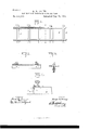
- FIG. 1 is a top plan view of a portion of a railroad embodying my invention.
- Fig. 2 is a cross-section on the line X X of Fig. 1.
- Fig. 3 is a section of a tie 011 the line Y Y of Fig. 1.
- Fig. 4 is a view showing the operation of the invention, the position of the spike when driven home being indicated by full lines and its position prior to being driven be ing indicated by dotted lines.
- the metal tie A is provided near its ends with retaining lugs or projections a a, which are cast or otherwise formed therewith.
- the spike-openings O are provided at a proper distance from the lugs a and are crooked or deflected from a straight line passing through their ends. These spikeopenings may be formed in the tie in any convenient manner,
- a tie preferably at the time of casting the tie, either by coring or in any other desired manner.
- the preferred way is to cast the ties in two parts and form the opening part way in the meeting faces of each. In this event the lugs to will be cast on one of the parts and project therefrom, so as to overlap the other part, as shown most clearly in Fig. 1.
- the operation of the invention is as follows:
- the ties are placed in position in the usual manner, and the rails are placed thereon in such a manner that the lugs a a will project over the foot thereof.
- the spikes which are of ordinary construction, are driven in the spike-openings, and as they advance are deflected or bent from a straight line and made to'conform to the outline of the spikeopening, as shown most clearly in Figs. 2 and at.
- the spike-openings are arranged opposite the retainingdugs a. Hence the spikes and the retaining-lugs act in conjunction to hold the rails on the tie.
- a metal tie formed in two pieces and having a crooked spike-opening formed part way in the meeting face of each part, substantially as set forth.
- the herein described metal tie composed of two parts, one part having an end lug cast therewith and adapted to overlap the other part and having a crooked spike-opening formed part way in. the meeting face of each part, substantially as specified.
Landscapes
- Engineering & Computer Science (AREA)
- Architecture (AREA)
- Civil Engineering (AREA)
- Structural Engineering (AREA)
- Footwear And Its Accessory, Manufacturing Method And Apparatuses (AREA)
Description
(No Model.)
' G. W. YOUNG.
RAILWAY RAIL FASTENING T0 METAL TIES.
No. 453,099. Patented May 26,1891.
W/ TIVESSES //v VE/V 10/2 73, JM/IW Georye i hlyazmzy.
I A rromvsyls:
UNITED STATES PATENT GFFIcE.
GEORGE \V. YOUNG, OF HELENA, MONTANA.
RAILWAY-RAIL FASTENING TO METAL TIES.
SPECIFICATION forming part of Letters Patent No. 453,099, dated May 26, 1891.
Application filed September 11, 1890. Serial No. 864,627. (No model.)
To all whom it nutty concern:
Be it known that I, GEORGE NV. YOUNG, a citizen of theUnited States,residingat Helena, in the county of Lewis and Clark and State of Montana, have invented certain new and useful Improvements in Railway-Rail Fastenings to Metal Ties; and I do hereby declare the following to be a full, clear, and exact de* scription of the invention, such as will enable others skilled in the art to which it appertains to make and use the same.
This invention relates to railway-rail fastenings, and aims to provide simple and effi cient means for securing the rails to the metal ties, which will not be affected by vibration, and which when in position cannot be readily withdrawn.
The improvement consists of the novel fea ture and peculiar construction and combination of the parts, which are hereinafter more fully described and claimed, and which are shown in the annexed drawings,in which-- Figure 1 is a top plan view of a portion of a railroad embodying my invention. Fig. 2 is a cross-section on the line X X of Fig. 1. Fig. 3 is a section of a tie 011 the line Y Y of Fig. 1. Fig. 4 is a view showing the operation of the invention, the position of the spike when driven home being indicated by full lines and its position prior to being driven be ing indicated by dotted lines.
Each of the ties is similarly constructed. Hence a detail description of one will suflice for all.
The metal tie A is provided near its ends with retaining lugs or projections a a, which are cast or otherwise formed therewith. The spike-openings O are provided at a proper distance from the lugs a and are crooked or deflected from a straight line passing through their ends. These spikeopenings may be formed in the tie in any convenient manner,
' preferably at the time of casting the tie, either by coring or in any other desired manner. The preferred way is to cast the ties in two parts and form the opening part way in the meeting faces of each. In this event the lugs to will be cast on one of the parts and project therefrom, so as to overlap the other part, as shown most clearly in Fig. 1.
The operation of the invention is as follows: The ties are placed in position in the usual manner, and the rails are placed thereon in such a manner that the lugs a a will project over the foot thereof. The spikes, which are of ordinary construction, are driven in the spike-openings, and as they advance are deflected or bent from a straight line and made to'conform to the outline of the spikeopening, as shown most clearly in Figs. 2 and at. The spike-openings are arranged opposite the retainingdugs a. Hence the spikes and the retaining-lugs act in conjunction to hold the rails on the tie.
I claim, and desire to secure by Letters Patcut, is
1. A metal tie formed in two pieces and having a crooked spike-opening formed part way in the meeting face of each part, substantially as set forth.
2. The herein described metal tie, composed of two parts, one part having an end lug cast therewith and adapted to overlap the other part and having a crooked spike-opening formed part way in. the meeting face of each part, substantially as specified.
In testimony whereof I affix my signature in presence of two witnesses.
GEORGE W. YOUNG. Witnesses:
HARRY O. BURGESS, MICHAEL H. WALL.
Having thus described my invention, what
Publications (1)
| Publication Number | Publication Date |
|---|---|
| US453099A true US453099A (en) | 1891-05-26 |
Family
ID=2521979
Family Applications (1)
| Application Number | Title | Priority Date | Filing Date |
|---|---|---|---|
| US453099D Expired - Lifetime US453099A (en) | Railway-rail fastening to metal ties |
Country Status (1)
| Country | Link |
|---|---|
| US (1) | US453099A (en) |
-
0
- US US453099D patent/US453099A/en not_active Expired - Lifetime
Similar Documents
| Publication | Publication Date | Title |
|---|---|---|
| US453099A (en) | Railway-rail fastening to metal ties | |
| US627435A (en) | Railway-rail | |
| US1070270A (en) | Railway-tie. | |
| US1074942A (en) | Railway-tie and rail-fastener. | |
| US1030896A (en) | Tie and rail-fastener. | |
| US845215A (en) | Track-fastening. | |
| US562960A (en) | Tie-plate and spike-lock | |
| US272850A (en) | Railroad-tie | |
| US763640A (en) | Rail-support. | |
| US682011A (en) | Railroad-tie. | |
| US531290A (en) | Railroad-rail | |
| US642427A (en) | Railway-tie. | |
| US376132A (en) | Railway-track | |
| US441002A (en) | Michael a | |
| US471582A (en) | Metallic railway-tie | |
| US390014A (en) | Railway | |
| US1007573A (en) | Rail-joint. | |
| US755151A (en) | Rail-joint. | |
| US880918A (en) | Railway-tie organization. | |
| US608648A (en) | Railway-tie | |
| US571743A (en) | Tie-plate and spike for railway-rails | |
| US1020298A (en) | Track appliance. | |
| US725665A (en) | Metallic tie and rail fastener. | |
| US715110A (en) | Rail-joint. | |
| US759969A (en) | Reversible railway-rail. |