US452991A - Mechanical movement - Google Patents
Mechanical movement Download PDFInfo
- Publication number
- US452991A US452991A US452991DA US452991A US 452991 A US452991 A US 452991A US 452991D A US452991D A US 452991DA US 452991 A US452991 A US 452991A
- Authority
- US
- United States
- Prior art keywords
- gear
- wheel
- shaft
- teeth
- plate
- Prior art date
- Legal status (The legal status is an assumption and is not a legal conclusion. Google has not performed a legal analysis and makes no representation as to the accuracy of the status listed.)
- Expired - Lifetime
Links
Images

Classifications
-
- F—MECHANICAL ENGINEERING; LIGHTING; HEATING; WEAPONS; BLASTING
- F16—ENGINEERING ELEMENTS AND UNITS; GENERAL MEASURES FOR PRODUCING AND MAINTAINING EFFECTIVE FUNCTIONING OF MACHINES OR INSTALLATIONS; THERMAL INSULATION IN GENERAL
- F16H—GEARING
- F16H1/00—Toothed gearings for conveying rotary motion
- F16H1/28—Toothed gearings for conveying rotary motion with gears having orbital motion
- F16H1/32—Toothed gearings for conveying rotary motion with gears having orbital motion in which the central axis of the gearing lies inside the periphery of an orbital gear
-
- Y—GENERAL TAGGING OF NEW TECHNOLOGICAL DEVELOPMENTS; GENERAL TAGGING OF CROSS-SECTIONAL TECHNOLOGIES SPANNING OVER SEVERAL SECTIONS OF THE IPC; TECHNICAL SUBJECTS COVERED BY FORMER USPC CROSS-REFERENCE ART COLLECTIONS [XRACs] AND DIGESTS
- Y10—TECHNICAL SUBJECTS COVERED BY FORMER USPC
- Y10T—TECHNICAL SUBJECTS COVERED BY FORMER US CLASSIFICATION
- Y10T408/00—Cutting by use of rotating axially moving tool
- Y10T408/65—Means to drive tool
- Y10T408/675—Means to drive tool including means to move Tool along tool-axis
- Y10T408/6779—Rack and pinion
Definitions
- Figure l a sectional plan illustrating the invention as applied to the feeding of the spindle of'an upright drill, the gear N being in the stationary position;
- Fig. 2 a vertical central section of the same on line/ y of Fig. l;
- Fig. 3 a vertical section on line of Fig. l;
- Fig. fi the same as Fig. l, representing the gear N as disengaged from its stationary position and engaged withthe shaft, so as to revolve therewith;
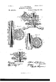
- Fig. 5 the invention as applied to moving the slide of a lathe Fig. 6
- the invention as applied to moving the slide of a shapingmachine.
- This invention relates to a mechanism for producing the feed in various kinds of machines for metal and other work, or generally for feeding, or for any purpose where a slow but steady movement is desired, the object being to very greatly reduce the velocity between the point where the power r is applied to work the feed and the object to be moved, and also to make the return movement quite rapid, if desirable.
- Such feed is employed in vertical drilling-machines, in engine-lathes, shapingqnachines, and various other machines, both for working metal and wood, and may be applied for other purposes.
- A represents the drill-spindle; B, the feeding-sleeve through which the drill-spindle works; C, the head within which the sleeve B is vertically movable; The sleeve is engaged with the spindle by means of a collar D at its ends made fast to the spindle and against which the sleeve will bear, so that Serial No. 379,072. (No model.)
- the gear-wheel is constructed with a concentrich ub G, which extends outward from one side, so as to rest in a bearing H in the casing or bracket and so as to revolve freely in the said bearing.
- the wheel is toothed upon its periphery, as seen in Fig.
- the teeth being adapted to work into a vertical correspondiugly-toothed rack I on the sleeve B, and so that the rotation of the wheelF willimpart corresponding vertical movement to the sleeve B and the spindle A.
- the wheel F is also internally toot-hed, so as to form an internal gear, as seen in Fig. 2, the interior series of teeth being concentric with the external series.
- a shaft J is arranged concentric with the gear F. It extends through the hub of the gear F, but is not connected with the said gear F, it being permitted free rotation therein. Vithin the gear F the body K of the shaft .l is eccentric to the shaft, as seen in Fig. 2. l
- a gear L is arranged, but loose upon the said eccentric.
- the teeth of this gear L correspond to the internal teeth of the gear F, and it is of such a diameter that, being eccentric to the said internal teeth of the gear F, the teeth of the gear L will work into the internal teeth of the gear F on the radius of the longer diameter of the eccentric body of the shaft, and as clearly Seen in Fig. 2.
- a second gear M Attached to the gear L or made as a part of it is a second gear M, concentric to the gear L.
- an internal gear N Surrounding this gear M is an internal gear N, supported in the bracket or case loose upon the shaft J, but concentric therewith, the teeth of the gear M corresponding to the internal teeth of the gear N, and so that the two come together on the longer radius of the IOO eccentric body of the shaft, as seen in Fig. 3.
- the gear N is supported in the bracket by a hub O, formed as a part of the gear and extending through the side of the bracket.
- This hub upon the outside is screw-threaded, and onthe screw-threaded portion is a nut P, which is adapted to be screwed against the bracket, so as to clamp the gear N .with the bracket, as seen in Fig. Lthat the gear N may become a stationary internal gear, or if released from the clamp the gear N is free to revolve.
- the gear N has a projection Q upon its outer end, which is of conical shape both upon its exterior and interior surfaces, as seen in Fig. l.
- the bracket or casing has a corresponding projection R, forming a conical internal recess corresponding to the external surface of the 'conical projection Q of the gear N, and so that as the nut P is turned against the bracket it will draw the said conical projection Qof the Wheel N into the recess of the projection R, and thereby produce friction sufcient to insure the holding of the wheel .N stationary with the bracket.
- a clutch-plate S is made fast to the shaft, its periphery corresponding to the recess or interior of the projection Q on the wheel; but the said plate S is arranged with relation to the said recess in the wheel N, so that the said wheel is permitted longitudinal play between the. said clutchplat'e'and its bearing-surface in the bracket, and as represented in Fig. l.
- the Wheel N is made fast to the bracket, as described, it is at its most distant position from the clutch-plate S, and so that the said clutchplate revolves with its shaft free and independent of the Wheel N; but it' the nut P be unscrewed and be brought to bear upon a collar T, made fast to the shaft J outside the nut, then the wheel N will be forced inward out of engagement with the bracket, but into engagement with the clutch-plate S, and forcibly interlock therewith by frictional contact.
- the wheel N will then revolve with the clutchplate S.
- the nut P is formed as the hub of a hand-wheel U, by which the nut may be conveniently turned, and the collar T is formed as the hub of a hand-Wheel V, by which it may be conveniently turned, the hand-Wheel thus forming a means for imparting rotation to the shaft J.
- the teeth of the several gears vary in number, and for convenience of illustration I represent the internal gear F as having twentyeight teeth, the gear L, which Works therein, with twenty-five teeth, the gear M as having twenty-three teeth, and the internal gear N twenty-six teeth. This completes the construction.
- the shaft J is arranged at right angles to the shaft b, and instead of the hand-wheel being applied to the shaft, so as to cause it to revolve, a beveled gear c is applied to the inner end of the shaft J, into which a corresponding piniond on the shaft b works, so that the revolution of the shaft Z) will impart corresponding revolution to the shaft J.
- Fig. 6 the mechanism is represented as applied to a shaping-machine.
- f represents the slide, into which the wheel F works, as in the first illustration.
- the clutch-plate S is made fast to or as a part of the hub of the gear N and is outside the bed.
- the periphery of the friction-plate S is made tapering from the center both outward and inward.
- a stationary clutch-plate g having an internal surface corresponding to the inner tapering surface of the clutch-plate S, and outside the clutch-plate S a drivingpulley 7L is applied to the shaft J, which will impart revolution thereto.
- the pulley 7L isshaped corresponding to the outer tapering surface of the clutch-plate S.
- the gear N,with the clutch-plate S, is permitted a limited amount of longitudinal Inovement, and the pulley 7i and the clutch-plate g are arranged distant from each other, so that both may not engage the clutch-plate at the same time.
- the longitudinal movement may be imparted tothe clutch-plate S and the wheel N by means of a longitudinal slide i, arranged in the shaft and engaged with the hub of the clutch-plate, as represented in Fig. G, so that a longitudinal movement imparted to the said slide t' will impart corresponding longitudinal movement to the clutch-plate S, this being a common device for imparting longitudinal movement to portions ot' machinery revolving with the shaft.
- the clutch-plate S When it is desired to hold the gear N stationary, as for feeding purposes, the clutch-plate S is forced into engagement with the stationary plate g, as represented. Then the feed will operate as in the first illustration; but when the rapid return is desired the clutch-plate S is drawn from its engagement with the stationary plate G and into engagement with the pulley Il, when the clutch-plate and the gear N will revolve with the pulley.
- the cinch-plate for engaging the gear N with the shaft may be omitted,as represented in Fig. 5.
- the clutching mechanism whereby the gear N is held stationary or forced to revolve with the shaft is a well-known expedient in mechanics and for which other well known clutching mechanism may be employed.
- wheel F being adapted to communicate its rotation, substantially as described.
- the said friction-plate corresponding to and adapted to engage the said conical surface of the gear N, a second internal gear F,'ar'ranged on said shaft and concentric thereto, but loose thereon, the shaft constructed with an Aeccentric body Within said internal gear, the gears M L, arranged on said eccentric portion of the shaft respectively Within and toothed corresponding to the teeth of the said linternal gears N F, but With lessnumber of teeth, the eccentricity of the shaft lbeing such as to bring the said internal gears M 'L into lengagement with their respective internal gears on the longest radius of the said eccentric, and the gear F adapted to communi-cate its rotation, substantially as described.
Landscapes
- Engineering & Computer Science (AREA)
- General Engineering & Computer Science (AREA)
- Mechanical Engineering (AREA)
- Gears, Cams (AREA)
Description
(No Modem. 2 Sheets-Sheet `2.
A. L. COLBURN. lMEGHJVICAL MOVEMENT.
No. 452,991. m9111911 May 29, 1891.
1 J. Y 9 L71 n u 1 1 F 9 y PATENT ALBERT L. COLBURN, OF NEV HAVEN, CONNECTICUT.
MECHANICAL MOVEMENT.
SPECIFICATION forming part of Letters Patent No. 452,991, dated May 26, 1891.
Application filed January 26. 1891.
.To a/ZZ whom, it may concern.-
, Be it known that I, ALBERT L. COLBURN, of New Haven, in the county of New Haven and State of Connecticut, have invented a new Improvement in Mechanical Movements; and I do hereby declare the following, when taken in connection with accompanying drawings and the letters of reference marked thereon, to be a full, clear, and exa-ct description of the same, and which said drawings constitute part of this specification, and represent, in
Figure l, a sectional plan illustrating the invention as applied to the feeding of the spindle of'an upright drill, the gear N being in the stationary position; Fig. 2, a vertical central section of the same on line/ y of Fig. l; Fig. 3, a vertical section on line of Fig. l; Fig. fi, the same as Fig. l, representing the gear N as disengaged from its stationary position and engaged withthe shaft, so as to revolve therewith; Fig. 5, the invention as applied to moving the slide of a lathe Fig. 6, the invention as applied to moving the slide of a shapingmachine.
This invention relates to a mechanism for producing the feed in various kinds of machines for metal and other work, or generally for feeding, or for any purpose where a slow but steady movement is desired, the object being to very greatly reduce the velocity between the point where the power r is applied to work the feed and the object to be moved, and also to make the return movement quite rapid, if desirable. Such feed is employed in vertical drilling-machines, in engine-lathes, shapingqnachines, and various other machines, both for working metal and wood, and may be applied for other purposes.
The invention consists in the combination of mechanism as hereinafter fully described, and particularly recited in the claims.
I will first illust-rate the invention as apapplied to an upright drill.
A represents the drill-spindle; B, the feeding-sleeve through which the drill-spindle works; C, the head within which the sleeve B is vertically movable; The sleeve is engaged with the spindle by means of a collar D at its ends made fast to the spindle and against which the sleeve will bear, so that Serial No. 379,072. (No model.)
while the spindle is free to revolve within the sleeve the sleeve and spindle are combined, so that the spindle will partake of any up-anddown movement imparted to the sleeve B, as usual in upright drills.
E represents a casing or bracket, which is attached to or made a part of the head C. This casing forms a chamber within which the feeding mechanism is arranged. YVithin this casing E agear-wheelFis arranged upon an axis at right angles to the axis of the spindle A. As here represented, the gear-wheel is constructed with a concentrich ub G, which extends outward from one side, so as to rest in a bearing H in the casing or bracket and so as to revolve freely in the said bearing. The wheel is toothed upon its periphery, as seen in Fig. 2, the teeth being adapted to work into a vertical correspondiugly-toothed rack I on the sleeve B, and so that the rotation of the wheelF willimpart corresponding vertical movement to the sleeve B and the spindle A. The wheel F is also internally toot-hed, so as to form an internal gear, as seen in Fig. 2, the interior series of teeth being concentric with the external series.
Through the bracket a shaft J is arranged concentric with the gear F. It extends through the hub of the gear F, but is not connected with the said gear F, it being permitted free rotation therein. Vithin the gear F the body K of the shaft .l is eccentric to the shaft, as seen in Fig. 2. l
On the body K of the shaft a gear L is arranged, but loose upon the said eccentric. The teeth of this gear L correspond to the internal teeth of the gear F, and it is of such a diameter that, being eccentric to the said internal teeth of the gear F, the teeth of the gear L will work into the internal teeth of the gear F on the radius of the longer diameter of the eccentric body of the shaft, and as clearly Seen in Fig. 2.
Attached to the gear L or made as a part of it is a second gear M, concentric to the gear L. Surrounding this gear M is an internal gear N, supported in the bracket or case loose upon the shaft J, but concentric therewith, the teeth of the gear M corresponding to the internal teeth of the gear N, and so that the two come together on the longer radius of the IOO eccentric body of the shaft, as seen in Fig. 3. The gear N is supported in the bracket by a hub O, formed as a part of the gear and extending through the side of the bracket. This hub upon the outside is screw-threaded, and onthe screw-threaded portion is a nut P, which is adapted to be screwed against the bracket, so as to clamp the gear N .with the bracket, as seen in Fig. Lthat the gear N may become a stationary internal gear, or if released from the clamp the gear N is free to revolve. The gear N has a projection Q upon its outer end, which is of conical shape both upon its exterior and interior surfaces, as seen in Fig. l. The bracket or casing has a corresponding projection R, forming a conical internal recess corresponding to the external surface of the 'conical projection Q of the gear N, and so that as the nut P is turned against the bracket it will draw the said conical projection Qof the Wheel N into the recess of the projection R, and thereby produce friction sufcient to insure the holding of the wheel .N stationary with the bracket.
On the shaft J and within the conical recess of the projection R a clutch-plate S is made fast to the shaft, its periphery corresponding to the recess or interior of the projection Q on the wheel; but the said plate S is arranged with relation to the said recess in the wheel N, so that the said wheel is permitted longitudinal play between the. said clutchplat'e'and its bearing-surface in the bracket, and as represented in Fig. l. lVhen the Wheel N is made fast to the bracket, as described, it is at its most distant position from the clutch-plate S, and so that the said clutchplate revolves with its shaft free and independent of the Wheel N; but it' the nut P be unscrewed and be brought to bear upon a collar T, made fast to the shaft J outside the nut, then the wheel N will be forced inward out of engagement with the bracket, but into engagement with the clutch-plate S, and forcibly interlock therewith by frictional contact.
The wheel N will then revolve with the clutchplate S. The nut P is formed as the hub of a hand-wheel U, by which the nut may be conveniently turned, and the collar T is formed as the hub of a hand-Wheel V, by which it may be conveniently turned, the hand-Wheel thus forming a means for imparting rotation to the shaft J.
The teeth of the several gears vary in number, and for convenience of illustration I represent the internal gear F as having twentyeight teeth, the gear L, which Works therein, with twenty-five teeth, the gear M as having twenty-three teeth, and the internal gear N twenty-six teeth. This completes the construction.
4Its operation is as follows: Supposing the wheel N to be clutched or made fast to the bracket, so that it remains stationary, as seen i'n Fig. l, the hand-Wheel V is turned, which imparts a corresponding revolution to the shaft J. This revolution of the shaft J causes the eccentric body of the shaft to revolve within the stationary Wheel N and within the wheel M-on the said eccentric body. Thus the movement of the eccentric body of the shaft will cause the wheel M to follow the path of the eccentric bodyof the shaft around the axis of the shaft proper, and were the teeth of the wheel M of the same number as the teeth of the gear N it would necessarily follow that there would simply be a continuous and regular engagement between the teeth of the t-wo wheels; but as t-he teeth of the Wheel M are less in number than the teeth of the wheel N it follows that a partial rotation must be imparted to the wheel Mto the extent of this differencein the number of teeth#- that is to say, the wheel M will have gained in one full revolution of the shaft J three teeth more than a full revolution of itself, The gear L, being made fast to and so as to revolve with the said gear M, has received the same extent of revolution beyond one complete revolution as did the wheel M, and it has traveled around the interior of the wheel F in like manner as did the wheel M within its wheel N, and Were the number of interior teeth of the wheel F the same as the number of teeth of the wheel L plus the number `of teeth included in the addition to a single revolution made by the Wheel L no effect would be produced upon the Wheel F; but the number of teeth of the wheel F being twenty-eight is less than the number of teeth included in the rotative movement which has been imparted to the wheel L. Consequently the wheel F will have been advanced according to this difference, as follows: twenty-three twentysixths divided by twenty-five twenty-eighths equals three hundred and twenty-five three hundred and twenty-seconds minus three hundred and twenty-two three hundred and twenty-seconds (because the wheel N of twenty-three teeth remains stationary) equals three three hundred and twenty-seconds of one revolution of the Wheel F with twentyeight teeth. The Wheel F, working into the vertical rack on the spindlecarrying sleeve B, will consequently impart to the sleeve a corresponding movement.
It will be understood thata variationin the number of teeth of the different wheels will produce a corresponding variation in the extent of feed movement produced. v This feed will continue so long as the shaft J is re- `volved, and this movement is intended for the feed of the drill. l
For the Withdrawal of the drill a more rapid movement is desirable. To produce this movement the nut P is unscrewed to release the wheel N from its clutch with the bracket, The nut is applied to force the Wheel N into engagement with the clutch-plate S, as seen in Fig. 4. The wheelN having noW become free from engagement with the bracket and brought into engagement with the shaft it will revolve with the shaft, and because it forcibly revolves with the shaft it revolves IOO IIO
also with the wheel M and .Y prevents any rotation of the wheel M, except with the shaft and the wheel N. Consequently the wheel L also revolves with the shaft and engages the wheel F, so that that wheel is also forced to revolve with the'shaft, and thus a revolution is imparted to the wheel F the same as'to the shaft and a corresponding quick movement will be imparted to the sleeve and spindle, so as to produce a rapid withdrawal.
As another illustration of the application of the invention for feeding purposes, I show in Fig. 5 its application to an engin e-lathe, in which a represents one side of the bed of the lathe; b, the longitudinal feed-shaft by which the feed is produced. In this case the shaft J is arranged at right angles to the shaft b, and instead of the hand-wheel being applied to the shaft, so as to cause it to revolve, a beveled gear c is applied to the inner end of the shaft J, into which a corresponding piniond on the shaft b works, so that the revolution of the shaft Z) will impart corresponding revolution to the shaft J. In this case there is substantially the same arrangement of gears as in the iirst illustration; but in this case the bracket or head E travels with the slide e of the lathe, and the rack I is stationary on the lathe-bed, into which the external teeth of the gear F work. Under this arrangement, the gears being proportioned as iirst described, there will be a like movement of the slide e. The gearN is represented as engaged with the bracket to hold it stationary, the same as in the first illustration, or to be released therefrom.
In Fig. 6 the mechanism is represented as applied to a shaping-machine. In this case f represents the slide, into which the wheel F works, as in the first illustration. As here represented, the clutch-plate S is made fast to or as a part of the hub of the gear N and is outside the bed. The periphery of the friction-plate S is made tapering from the center both outward and inward. Upon the inside of the plate S is a stationary clutch-plate g, having an internal surface corresponding to the inner tapering surface of the clutch-plate S, and outside the clutch-plate S a drivingpulley 7L is applied to the shaft J, which will impart revolution thereto. Upon the inner side the pulley 7L isshaped corresponding to the outer tapering surface of the clutch-plate S. The gear N,with the clutch-plate S, is permitted a limited amount of longitudinal Inovement, and the pulley 7i and the clutch-plate g are arranged distant from each other, so that both may not engage the clutch-plate at the same time. The longitudinal movement may be imparted tothe clutch-plate S and the wheel N by means of a longitudinal slide i, arranged in the shaft and engaged with the hub of the clutch-plate, as represented in Fig. G, so that a longitudinal movement imparted to the said slide t' will impart corresponding longitudinal movement to the clutch-plate S, this being a common device for imparting longitudinal movement to portions ot' machinery revolving with the shaft. When it is desired to hold the gear N stationary, as for feeding purposes, the clutch-plate S is forced into engagement with the stationary plate g, as represented. Then the feed will operate as in the first illustration; but when the rapid return is desired the clutch-plate S is drawn from its engagement with the stationary plate G and into engagement with the pulley Il, when the clutch-plate and the gear N will revolve with the pulley.
I have represented the wheel F as adapted to communicate its motion by means of gearteeth upon its periphery; but it will be un` derstood that any of the known substitutes for communicating motion maybe employedas, for illustration, friction-al contact or a travcling band or chain--devices too well known to require illustration.
The cinch-plate for engaging the gear N with the shaftmay be omitted,as represented in Fig. 5.
The clutching mechanism whereby the gear N is held stationary or forced to revolve with the shaft is a well-known expedient in mechanics and for which other well known clutching mechanism may be employed.
These illustrations will be sufficient to enable others skilled in the art to apply this mechanical movement to the various purposes for which it is adapted.
I am aware that the combination of several differential gears has been arranged upon a single shaft, whereby a great reduction in the velocity of revolution is obtained be? tween the peint where power is applied and where the power is exerted either for the great increase of power or corresponding reduction in speed, and therefore donot broadly claim such an arrangement of differential gearing.
I claim.dh
l. The combination of a shaftJ, supported in bearings and adapted for revolution, an internal gear N, concentric with said shaft, with mechanism, substantially such as de scribed, to hold the said gear N stationary or permit its revolution, as the case may be, a second internallytoothed wheel F, also ar-` ranged concentric With said shaft but loose thereon, the shaft constructed with an eccentric body within said internal gears, a gear M, arranged loose on said eccentric body but concentric thereto, the said gear M having teeth corresponding to the internal teeth of the gear N, but less in number, a gear L, arranged loose on said eccentric body within the wheel F, but in connection with the said gear M and so as to revolve therewith, and having teeth corresponding to the internal teeth of the said wheel F, but less in number, the eccentricity of the said body of the shaft being such as to bring the teeth of the said two gears M L into engagement with the teeth of their respective internal gears on the longest radius of -the said eccentric, the said TOO IIC
wheel F being adapted to communicate its rotation, substantially as described.
2. The combination of the revolving shaft J, the internal gear N, concentric with said shaft, butloosethereon,thehub of the saidgear extend-ing through a bearing lof its oWn, the said hub screw-threaded outside said bearing, With a nut thereon adapted to clamp the sa-id gear vin its bearing to hold it stationary or release it therefrom to permitl its revolution, a second internal gear F, concentric with and loose upon said shaft, the shaft constructed Withran eccentric body within said internal gears, la gear M, arranged upon said eccentric body Within the gear N and lhaving its teeth corresponding thereto, but less in number, a .gear L,.arranged on said eccentric, but loose thereon wit-hin the Wheel F., the teeth of the Wheel L corresponding to the internal teeth of the said gear F, said gears L and M being connected so as to revolve together, the eccenvtricityof the said body of the shaft being such as to bring the teeth of the said gears L M into engagement with the said internal fgears on the longest diameter of the said eccentric, the said wheel F being adapted to communicate its rotation, substantially as described.
3. The combination of the shaft J, an internal gear N, concentric with but loose upon t said shaft, the hub of the said gear N extending through itsl bearing and screw-threaded upon its outside, anut-on said screw-threaded hub adapted to clamp the said gear N stationary in its bearing or release it therefrom, .the said gear N constructed with an internal concentric conical surface, a frictionfpla'te S,
fixed to said shaft so as to revolve therewith, the said friction-plate corresponding to and adapted to engage the said conical surface of the gear N, a second internal gear F,'ar'ranged on said shaft and concentric thereto, but loose thereon, the shaft constructed with an Aeccentric body Within said internal gear, the gears M L, arranged on said eccentric portion of the shaft respectively Within and toothed corresponding to the teeth of the said linternal gears N F, but With lessnumber of teeth, the eccentricity of the shaft lbeing such as to bring the said internal gears M 'L into lengagement with their respective internal gears on the longest radius of the said eccentric, and the gear F adapted to communi-cate its rotation, substantially as described.
In testimony whereof I have signed lthis specification in the presence of two subscribing witnesses.
ALBERT L. COLBURN.
lVitnesses:
FRED C. EARLE,
LILLIAN D. KELSEY.
Publications (1)
| Publication Number | Publication Date |
|---|---|
| US452991A true US452991A (en) | 1891-05-26 |
Family
ID=2521871
Family Applications (1)
| Application Number | Title | Priority Date | Filing Date |
|---|---|---|---|
| US452991D Expired - Lifetime US452991A (en) | Mechanical movement |
Country Status (1)
| Country | Link |
|---|---|
| US (1) | US452991A (en) |
Cited By (5)
| Publication number | Priority date | Publication date | Assignee | Title |
|---|---|---|---|---|
| US2416611A (en) * | 1946-02-14 | 1947-02-25 | Altorfer Bros Co | Clothes washing machine |
| US2645139A (en) * | 1949-12-27 | 1953-07-14 | Beauloye Max | Portable boring mill |
| US2933986A (en) * | 1955-09-30 | 1960-04-26 | Cincinnati Milling Machine Co | Spindle control mechanism |
| US3373658A (en) * | 1965-10-19 | 1968-03-19 | Gorton Machine Corp | Metalworking machine |
| US5081478A (en) * | 1990-02-13 | 1992-01-14 | Fuji Photo Film Co., Ltd. | Adjustably mounted camera grip |
-
0
- US US452991D patent/US452991A/en not_active Expired - Lifetime
Cited By (6)
| Publication number | Priority date | Publication date | Assignee | Title |
|---|---|---|---|---|
| US2416611A (en) * | 1946-02-14 | 1947-02-25 | Altorfer Bros Co | Clothes washing machine |
| US2645139A (en) * | 1949-12-27 | 1953-07-14 | Beauloye Max | Portable boring mill |
| US2933986A (en) * | 1955-09-30 | 1960-04-26 | Cincinnati Milling Machine Co | Spindle control mechanism |
| US3373658A (en) * | 1965-10-19 | 1968-03-19 | Gorton Machine Corp | Metalworking machine |
| US5081478A (en) * | 1990-02-13 | 1992-01-14 | Fuji Photo Film Co., Ltd. | Adjustably mounted camera grip |
| EP0622663A1 (en) * | 1990-02-13 | 1994-11-02 | Fuji Photo Film Co., Ltd. | Camera grip with gear mechanism |
Similar Documents
| Publication | Publication Date | Title |
|---|---|---|
| US452991A (en) | Mechanical movement | |
| US799131A (en) | Gearing for portable tools. | |
| US170605A (en) | Improvement in engine-lathes | |
| US138742A (en) | Improvement in machines for boring hubs | |
| US475901A (en) | Gearing | |
| US733719A (en) | Multiple-drill attachment for drill-presses. | |
| US704645A (en) | Differential-speed mechanism. | |
| US788483A (en) | Head-stock for engine-lathes. | |
| US749186A (en) | Ho model | |
| US437067A (en) | Speed-changing mechanism for lathes | |
| US724312A (en) | Variable-speed gear. | |
| US711448A (en) | Drilling-machine. | |
| US716930A (en) | Variable-speed gear. | |
| US421866A (en) | Edward a | |
| US1032245A (en) | Variable-speed gearing for motor-cycles. | |
| US718800A (en) | Expansible pulley. | |
| US561198A (en) | Counter-shaft | |
| US844390A (en) | Gearing for drilling-machines, &c. | |
| US864824A (en) | Variable-speed gearing. | |
| US1231880A (en) | Gearing. | |
| US1387550A (en) | Friction transmission mechanism | |
| US506620A (en) | Milling-machine | |
| USRE14755E (en) | Fbictioir-ci | |
| US994899A (en) | Gearing. | |
| US1113814A (en) | Change-speed mechanism for motor-cycles. |