US452896A - Clay-disintegrating mill - Google Patents
Clay-disintegrating mill Download PDFInfo
- Publication number
- US452896A US452896A US452896DA US452896A US 452896 A US452896 A US 452896A US 452896D A US452896D A US 452896DA US 452896 A US452896 A US 452896A
- Authority
- US
- United States
- Prior art keywords
- drum
- clay
- doors
- disintegrating mill
- cylinder
- Prior art date
- Legal status (The legal status is an assumption and is not a legal conclusion. Google has not performed a legal analysis and makes no representation as to the accuracy of the status listed.)
- Expired - Lifetime
Links
- 239000004927 clay Substances 0.000 description 13
- 238000005496 tempering Methods 0.000 description 6
- 208000028659 discharge Diseases 0.000 description 4
- 238000000034 method Methods 0.000 description 3
- 241000220317 Rosa Species 0.000 description 2
- 239000002184 metal Substances 0.000 description 2
- XLYOFNOQVPJJNP-UHFFFAOYSA-N water Substances O XLYOFNOQVPJJNP-UHFFFAOYSA-N 0.000 description 2
- 230000001174 ascending effect Effects 0.000 description 1
- 239000011449 brick Substances 0.000 description 1
- 229910000078 germane Inorganic materials 0.000 description 1
- 238000000465 moulding Methods 0.000 description 1
- 230000002093 peripheral effect Effects 0.000 description 1
- 230000001105 regulatory effect Effects 0.000 description 1
- 230000000284 resting effect Effects 0.000 description 1
- 239000007787 solid Substances 0.000 description 1
- 239000002023 wood Substances 0.000 description 1
Images

Classifications
-
- B—PERFORMING OPERATIONS; TRANSPORTING
- B01—PHYSICAL OR CHEMICAL PROCESSES OR APPARATUS IN GENERAL
- B01F—MIXING, e.g. DISSOLVING, EMULSIFYING OR DISPERSING
- B01F27/00—Mixers with rotary stirring devices in fixed receptacles; Kneaders
Definitions
- HORACE B CAMP, OF CUYAHOGA FALLS, OHIO.
- the object and purpose of my invention is to produce an improved machine for tempering clay preparatory to its use in brick, tile, sewer-pipe, or other forming or molding machines, and is ancillary and germane to a machine for disintegrating clay, for which I have made application for Letters Patent under date of May 5, 1890, Serial No. 350,601.
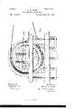
- Figure l is an end elevation of a machine embodying my invention
- Fig. 2 a central vertical longitudinal section of the same at the line so as of Fig. 1.
- A is a frame, preferably of wood beams, as shown, and securely fastened to a floor B by bolts C, as shown, or by other equivalent or preferred device.
- J ournaled in suitable bearings on this frame are flanged rollers E, preferably mounted on parallel shafts D.
- a drum F Resting and revolubly mounted on the rollersE is a drum F, consisting of two oppositely-disposed annular disks G G, preferably of cast metal, united bya shell or hoop 11, preferably of sheet metal, bolted to inner annular flanges extending from said disks.
- This drum as shown, is revolved by means of a belt J, which runs on an annular flange I, attached to the disk G, and is driven from any convenient pulley; but this method of revolving the drum is not essential, as it may be accomplished by other means, as hereinafter described.
- heads or covers K K respectively attached to the frame Aby brackets or straps L L, which covers serve to prevent the esloosely either by these brackets orsome similar device, so that they may yield slightly to inequalities in the shape of the inner periphery of the disks G G or the motion of the drum in its revolutions.
- a shaft M which bears outside of the drum a pulley P and inside the drum a solid cylinder N, inserted in and projecting from which are radial pins 11, and which, for the purpose of this application, may be denominated the mixer.
- the shaft M is mounted eccentric to and parallel with the axis of the drum F, and when the cylinder N bears the relation to the drum F shown is preferably in the same horizontal plane.
- a belt Q drives the pulley P from any con venient power in a direction opposite to the motion of the drum.
- a hopper S Suspended by the frame A below the drum F is a hopper S, terminating at the bottom in a delivery-spout, through which the tempered clay is discharged.
- a series of openings T disposed at intervals lengthwise of and about the drum, each closed with a hinged door U, the hinges of the doors being in the direction of the revolution of the drum.
- These doors are fastened when desired by latches (not shown) of any desired or approved pattern, and when these latches are released the descending doors, when about the horizontal plane of the axis of the drum, will open by gravitation, while the opposite ascending doors will close.
- a pipe V connected with a water-supply under pressure, and terminating in a rose or spraynozzle, the object and purpose of which is to sprinkle and moisten the clay in the drum and which pipe is provided with a gate by which the supply of water may be regulated.
- This rose may be placed at any desired point in the drum, and in some cases it will be found advantageous to provide two or more or to substitute a finely-perforated pipe running across the drum.
- the doors U are closed and latched, and the drum F and mixer N are revolved in opposite directions, the former slowly and the latter rapidly, their relative degrees of speed will be determined by the character, condition, and requirement of the clay to be tempered.
- the clay preferably disintegrated or ground, is then fed into the drum through the door R and moistened by water from the pi peV until a sufficient charge has been placed in the drum and properly moistened.
- the moistened clay is continually carried up on the inside periphery of the drum until it encounters the pins 02, by which it is violently stirred and thrown back upon the coming mass, and this is continued until it is properly tempered and perfectly homogeneous, when the latches of the doors U are released and the tempered clay falls through the openings T into the hopper S.
- a clay-tempering machine consisting of a revolubly-mounted horizontal drum having peri phcral discharge-doors, a mixing-cylinder having radial pins revolubly mounted inside of, parallel with, and axially eccentric to said drum in bearings outside thereof, and means, as belts, for independently simultaneously revolving said drum and mixing-cylinder in opposite directions with different degrees of speed, substantially as shown and described.
- a clay-tempering machine In a clay-tempering machine, the combination, with a revolving drum having peripheral discharge-doors, and a mixing-cylinder having radial pins mounted to revolve inside of said drum axially eccentric thereto, of covers arranged to close the end openings of said drum, one whereof is provided with a feedingdoor, and means, as belts, for simultaneously revolving said drum and mixing-cylinder in opposite directions with different degrees of I speed, substantially as shown and described.
- a clay-tempering machine embodying the following elements: a supporting-frame, a drum having end openings revolubly mounted thereon and provided with dis charge-gates, a mixer having radial pins revolubly mounted in and axially eccentric to said drum, covers for the end openings of said drum, one whereof is provided with a feeding-door, a hopper to receive the clay from said discharge-gates, and a water-supply pipe arranged to moisten the clay within the drum, all constructed and arranged substantially as shown, and for the purpose specified.
Landscapes
- Chemical & Material Sciences (AREA)
- Chemical Kinetics & Catalysis (AREA)
- Preparation Of Clay, And Manufacture Of Mixtures Containing Clay Or Cement (AREA)
- Treatment Of Fiber Materials (AREA)
Description
(No Model.) ,2 Sheets-Sheet 1. H. B. CAMP. CLAY DISINTEGRATING MILL.
Patented May 26, 1891.
jwrawto 7: Jforace 1?. Cam, 2:9 ahtarway (Nd Model.) 2 Sheets-Sheet 2 H. B. CAMP.
CLAY DISINTEGBATING MILL.
g Pgtented'May 26, 1891.
Horace E. (760796,
(56? 24 44 2 WW w Jffar'nely,
UNITED STATES PATENT OFFICE,
HORACE B. CAMP, OF CUYAHOGA FALLS, OHIO.
CLAY-DISINTEGRATING MILL.
SPECIFICATION forming part of Letters Patent N 0. 452,896, dated May 26, 1891. Application filed July 21, 1890. Serial No. 359,356. (No model.)
To all whom it hwy concern:
Be it known that I, HORACE B. CAMP, a citizen of the United States, residing at Cuyahoga Falls, in the county of Summit and State of Ohio, have invented a certain new and useful Improvement in Clay-Tempering Machines, of which the following is a specification.
The object and purpose of my invention is to produce an improved machine for tempering clay preparatory to its use in brick, tile, sewer-pipe, or other forming or molding machines, and is ancillary and germane to a machine for disintegrating clay, for which I have made application for Letters Patent under date of May 5, 1890, Serial No. 350,601.
To this object and purpose my invention consists in certain peculiar and novel c011- struction, combination, and arrangement of parts hereinafter described, and then specifically pointed out in the claims, reference being had to the accompanying drawings, forming a part of this specification.
In the accompanying drawings, in which similar letters of reference indicate like parts, Figure l is an end elevation of a machine embodying my invention, and Fig. 2 a central vertical longitudinal section of the same at the line so as of Fig. 1.
Referring to the drawings, A is a frame, preferably of wood beams, as shown, and securely fastened to a floor B by bolts C, as shown, or by other equivalent or preferred device. J ournaled in suitable bearings on this frame are flanged rollers E, preferably mounted on parallel shafts D. Resting and revolubly mounted on the rollersE is a drum F, consisting of two oppositely-disposed annular disks G G, preferably of cast metal, united bya shell or hoop 11, preferably of sheet metal, bolted to inner annular flanges extending from said disks. This drum, as shown, is revolved by means of a belt J, which runs on an annular flange I, attached to the disk G, and is driven from any convenient pulley; but this method of revolving the drum is not essential, as it may be accomplished by other means, as hereinafter described. In opposite end openings of this drum are heads or covers K K, respectively attached to the frame Aby brackets or straps L L, which covers serve to prevent the esloosely either by these brackets orsome similar device, so that they may yield slightly to inequalities in the shape of the inner periphery of the disks G G or the motion of the drum in its revolutions.
.Iournaled in suitable bearings in the frame A and passing through openings in the covers K K is a shaft M, which bears outside of the drum a pulley P and inside the drum a solid cylinder N, inserted in and projecting from which are radial pins 11, and which, for the purpose of this application, may be denominated the mixer.
The shaft M is mounted eccentric to and parallel with the axis of the drum F, and when the cylinder N bears the relation to the drum F shown is preferably in the same horizontal plane. By this arrangement the moistened clay as it is carried upward on the inner periphery of the drum F is encountered by the pins '12 and thrown backward, as hereinafter described.
A belt Q drives the pulley P from any con venient power in a direction opposite to the motion of the drum. Suspended by the frame A below the drum F is a hopper S, terminating at the bottom in a delivery-spout, through which the tempered clay is discharged.
In the periphery of the drum F are a series of openings T, disposed at intervals lengthwise of and about the drum, each closed with a hinged door U, the hinges of the doors being in the direction of the revolution of the drum. These doors are fastened when desired by latches (not shown) of any desired or approved pattern, and when these latches are released the descending doors, when about the horizontal plane of the axis of the drum, will open by gravitation, while the opposite ascending doors will close. Through the cover K is a pipe V, connected with a water-supply under pressure, and terminating in a rose or spraynozzle, the object and purpose of which is to sprinkle and moisten the clay in the drum and which pipe is provided with a gate by which the supply of water may be regulated. This rose may be placed at any desired point in the drum, and in some cases it will be found advantageous to provide two or more or to substitute a finely-perforated pipe running across the drum.
In operation the doors U are closed and latched, and the drum F and mixer N are revolved in opposite directions, the former slowly and the latter rapidly, their relative degrees of speed will be determined by the character, condition, and requirement of the clay to be tempered. The clay, preferably disintegrated or ground, is then fed into the drum through the door R and moistened by water from the pi peV until a sufficient charge has been placed in the drum and properly moistened. During this process the moistened clay is continually carried up on the inside periphery of the drum until it encounters the pins 02, by which it is violently stirred and thrown back upon the coming mass, and this is continued until it is properly tempered and perfectly homogeneous, when the latches of the doors U are released and the tempered clay falls through the openings T into the hopper S.
As hereinbefore suggested, I do not attempt in this application to give the precise relative proportions of the different parts or their exact positions, as these must of necessity differ with the different requirements of the machine and as experience may determine to be best-as, for instance, the cylinder N may be increased in size or reduced to the shaft M, and as a consequence the pins n will differ in length and mode of attachment, as they may in shape, and the flange I and belt J may be omitted and the power. applied directly to the pulley P, and thence by any Wellknown device, as sprocket wheels and chain, to the rollers E, without departing from my invention, which I claim to be 1. A clay-tempering machine consisting of a revolubly-mounted horizontal drum having peri phcral discharge-doors, a mixing-cylinder having radial pins revolubly mounted inside of, parallel with, and axially eccentric to said drum in bearings outside thereof, and means, as belts, for independently simultaneously revolving said drum and mixing-cylinder in opposite directions with different degrees of speed, substantially as shown and described. 2. In a clay-tempering machine, the combination, with a revolving drum having peripheral discharge-doors, and a mixing-cylinder having radial pins mounted to revolve inside of said drum axially eccentric thereto, of covers arranged to close the end openings of said drum, one whereof is provided with a feedingdoor, and means, as belts, for simultaneously revolving said drum and mixing-cylinder in opposite directions with different degrees of I speed, substantially as shown and described.
3. In a clay-tempering machine, the combination, with a revolubly mounted horizontal drum, and a mixing-cylinder having radial pins mounted to revolve inside of said drum in bearings outside thereof, of a water-supply pipe extending into said drum and provided with a spray-n ozzle or rose to moisten the clay in the process of mixing, substantially as shown and described.
4. A clay-tempering machine embodying the following elements: a supporting-frame, a drum having end openings revolubly mounted thereon and provided with dis charge-gates, a mixer having radial pins revolubly mounted in and axially eccentric to said drum, covers for the end openings of said drum, one whereof is provided with a feeding-door, a hopper to receive the clay from said discharge-gates, and a water-supply pipe arranged to moisten the clay within the drum, all constructed and arranged substantially as shown, and for the purpose specified.
In testimony that I claim the above I hereunto set my hand.
IIORACE B. CAMP.
In presence of'- a.
O. P. HUMPHREY, C. E. I'IUMPHREY.
Publications (1)
| Publication Number | Publication Date |
|---|---|
| US452896A true US452896A (en) | 1891-05-26 |
Family
ID=2521776
Family Applications (1)
| Application Number | Title | Priority Date | Filing Date |
|---|---|---|---|
| US452896D Expired - Lifetime US452896A (en) | Clay-disintegrating mill |
Country Status (1)
| Country | Link |
|---|---|
| US (1) | US452896A (en) |
Cited By (2)
| Publication number | Priority date | Publication date | Assignee | Title |
|---|---|---|---|---|
| US3912233A (en) * | 1972-07-10 | 1975-10-14 | Basf Ag | Apparatus for continuous treatment and processing of solid and/or liquid materials |
| US20080095902A1 (en) * | 2006-10-18 | 2008-04-24 | George Cheung | Marinating device |
-
0
- US US452896D patent/US452896A/en not_active Expired - Lifetime
Cited By (5)
| Publication number | Priority date | Publication date | Assignee | Title |
|---|---|---|---|---|
| US3912233A (en) * | 1972-07-10 | 1975-10-14 | Basf Ag | Apparatus for continuous treatment and processing of solid and/or liquid materials |
| US20080095902A1 (en) * | 2006-10-18 | 2008-04-24 | George Cheung | Marinating device |
| US20090255416A1 (en) * | 2006-10-18 | 2009-10-15 | George Cheung | Marinating device |
| US7670042B2 (en) * | 2006-10-18 | 2010-03-02 | George Cheung | Marinating device |
| US8360628B2 (en) * | 2006-10-18 | 2013-01-29 | George Cheung | Marinating device |
Similar Documents
| Publication | Publication Date | Title |
|---|---|---|
| US2868351A (en) | Material thrower or impactor | |
| US2146776A (en) | Feed mixer | |
| US452896A (en) | Clay-disintegrating mill | |
| US409956A (en) | Malting and germinating apparatus | |
| US400807A (en) | Apparatus for malting grain | |
| US2924847A (en) | Method and apparatus for nodulization of pulverulent materials | |
| US752646A (en) | Combined sand screen and mixer | |
| US1038698A (en) | Concrete-mixer. | |
| US1096103A (en) | Method and apparatus for mixing concrete. | |
| US1190829A (en) | Drier. | |
| US833790A (en) | Mixing-machine. | |
| US458435A (en) | Feeding mechanism for cotton-seed-delinting machines | |
| US1213407A (en) | Concrete mixer and conveyer. | |
| US1877517A (en) | Method of grinding | |
| US1540600A (en) | Drying machine | |
| US284115A (en) | Machine foe sanding molds foe beiok | |
| US452895A (en) | Clay disintegrating and separating mill | |
| US876270A (en) | Concrete-mixer. | |
| US974180A (en) | Dry-pan. | |
| US618644A (en) | Cotton-seed roaster | |
| US660205A (en) | Grain-scourer. | |
| US223086A (en) | Improvement in malt-turning machines | |
| US1045342A (en) | Feeding means for tube-mills and like grinding apparatus. | |
| US3033A (en) | Smut-machine | |
| SU479487A1 (en) | Impact crusher |