US452814A - Running-gear for wagons - Google Patents
Running-gear for wagons Download PDFInfo
- Publication number
- US452814A US452814A US452814DA US452814A US 452814 A US452814 A US 452814A US 452814D A US452814D A US 452814DA US 452814 A US452814 A US 452814A
- Authority
- US
- United States
- Prior art keywords
- sand
- board
- axle
- bolster
- wagon
- Prior art date
- Legal status (The legal status is an assumption and is not a legal conclusion. Google has not performed a legal analysis and makes no representation as to the accuracy of the status listed.)
- Expired - Lifetime
Links
- 238000010276 construction Methods 0.000 description 7
- 230000000694 effects Effects 0.000 description 4
- 230000000284 resting effect Effects 0.000 description 3
- 239000002184 metal Substances 0.000 description 2
- 238000005452 bending Methods 0.000 description 1
- 244000309464 bull Species 0.000 description 1
- 230000003292 diminished effect Effects 0.000 description 1
- 230000003467 diminishing effect Effects 0.000 description 1
- 238000006073 displacement reaction Methods 0.000 description 1
- 230000000630 rising effect Effects 0.000 description 1
- 230000002459 sustained effect Effects 0.000 description 1
Images


Classifications
-
- B—PERFORMING OPERATIONS; TRANSPORTING
- B60—VEHICLES IN GENERAL
- B60G—VEHICLE SUSPENSION ARRANGEMENTS
- B60G7/00—Pivoted suspension arms; Accessories thereof
- B60G7/001—Suspension arms, e.g. constructional features
Definitions
- the object of this invention is to furnish a means of applying springs to the bolster or the sand-board of an ordinary farm-wagon.
- the sand-board or bolster is held firmly in a vertical path over the axle, and the jolting of the wagon-body is transmitted to the axle with the least damage to the fixtures.
- My construction is not intended to produce an easy-riding wagon, like a spring-wagon, but to diminish the effect of jolting upon the load and rider in a considerable degree and to increase the durability of a farm-wagon by diminishing the effect of such jars.
- Figure 1 is a plan of the parts attached to the front axle, excepting the wheels, with the reach and bolster in dotted lines to represent their relation to the front axle when turned.
- Fig. 2 is a front elevation of the same parts with the wagon-body and the bolster resting upon the sand-board.
- Fig. 3 is a side elevation of the parts shown in Figs. 1 and 2.
- Fig. 4- is a longitudinal section at the center of the axle upon the line 00 as in Fig. 1.
- Fig. 5 is a transverse section of the same parts, with the tie-bar in section on line ,2 z in Fig. .2.
- Fig. 1 is a plan of the parts attached to the front axle, excepting the wheels, with the reach and bolster in dotted lines to represent their relation to the front axle when turned.
- Fig. 2 is a front elevation of the same parts with the wagon-body and the bolster resting upon the sand-board.
- Fig. 3 is a side elevation
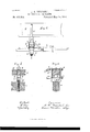
- Fig. 6 is a plan of the rear axle with the reach and hounds attached to the same and the bolster removed.
- Fig. 7 is an end view of the same parts upon a larger scale in section on line a .cn in Fig. 8, and Fig. 8 a side view of one end of the axle and bolster.
- Fig. 9 is an end view, and Fig. 10 a side view, of the slotted abutment.
- a is the front axle
- b the sand-board
- c the reach
- d the bolster
- W is the wagon-body, and tthe stakes which hold it upon the bolster.
- 7b are the hounds, bolted across the axle, as usual, and e are spiral springs fitted between the axle and sand-board, with a metal plate 6' attached to the sand-board at the top of the spring and a cup 6 attached to the axle at the bottom of the spring to hold the spring in place.
- f are guide-bars projected up wardfroin the axle past each side of the sand-board.
- the bars are shown in Fig. 5 formed in one piece with a foot f, which is bolted to the top of the axle.
- earing-plates g are applied between the guides and the edges of the sand-board to protect the latter, and are shown formed with vertical ribs 7a to hold the sand-board from end movement.
- the bars f and plates g form the wearing-bearing.
- a brace m is attached to the side of the hounds and extended through holes m in the guide-bars.
- the plates 9 are shown projected below the bottom of the sand-board and formed with slots h to clear the brace m.
- a tie-bar a is also attached to the hounds and extended through holes in the guides above the sand-board.
- the brace and tie-bar are both formed with shoulders s the opposite side to hold the guides from spreading at the top.
- Turning-plates p are applied to the top of the sand-board and the bolster, as is common, and the bolster and wagon-body are free to turn upon the top of at one side of the guides and with nuts 0 at 9 the sand-board, as is usual.
- Such turning is expressed by the dotted lines o and d, which represent the reach and bolster at an angle with the axle in Fig. 1.
- the sand-board is movable between the guides f, but in a vertical direction only, the ribs h preventing any end movement of the sand-board and the brace at preventing any lateral movement, which might result from a straining of the guides if no tie were used.
- an elastic bearing can be furnished to the wagon-body upon the front axle with very little elevation of the wagon-body above its normal height. This is effected by utilizing the space between the axle and sand-board which is commonly required to introduce the reach and the hounds. Although such space may not be entirely sufficient to introduce the required springs, a very little elevation of the sand-board above the hounds suffices for such purpose, as is clearly shown in Fig. 2, where the springs are shown represented as extended to their full height. The load upon the wagon would press the springs downward and permit the sandboard to approach the hounds and reach in some degree.
- the brace 01 extends between the guidesf over the top of the sandboard, and thus holds the sand-board in its normal position upon the springs whenever the wagon-body and its bolster are lifted off. The sand-board and the springs are thus prevented from displacement and constitute a permanent attachment of the axle.
- Figs. 7 and 8 like Figs. 2 and 3, show a portion of the wagon-body resting directly upon the rear bolster B, and in such construction the parts f of the wearing-bearing cannot be extended up beyond the top of the bolster, and the tie-bar n is therefore necessarily omitted.
- the bars f are shown with lndependent feet 19 bolted upon the top of the hounds F by bolts 1).
- the brace m is in this construction as effective as the combined brace and tie-bar it applied to the sand-board, for the reason that the wagon body, resting directly upon the bolster, has much less leverage to wrench the wearingbearing than where it is supported a considerable distance above the sand-board over the front axle.
- a slotted abutment r (shown in Figs. 7 to 10) is inserted between the plates g and bolted to the under side of the bolster, with its slot in a line with the slots 72, in such plates.
- the abutment prevents the bending of the plates under the jolting of the body, and thus preserves the wearing-bearing from damage.
- the engagement of the slots with the brace also restrains the wagonbody from lurching sidewise over the axle, and the wearing-bearing thus controls and guides the movement of the body in every direction.
- the brace m sustains the entire thrust upon the wearing-bearing by means of the shoulder sin contact with one of the plates and the nut 0 in contact with the other.
- the shoulder and nut operate to clamp the bracerod in the holes in the wearing-bearing, and it is therefore obvious that any equivalent fastening may be used instead of the nut, and the bars f and the brace-rod may also be attached to the running-gear firmly in any convenient manner without departing from my invention.
- Fig. 2 of the drawings are shown beneath the ends of the sand-board, which transmits the weight of the load to the axle as close as possible to the wheels.
- the springs may, however, be inserted between the sand-board and axle at other points, if preferred.
- the sand-board of a wagon may be made movable over the front axle and sustained upon springs, while at the same time it is held rigidly from lurching in any direction, and thus serves as an efficient support for the front bolster d, which is required to constantly turn upon the king-bolt when the wagon is in use.
Landscapes
- Engineering & Computer Science (AREA)
- Mechanical Engineering (AREA)
- Handcart (AREA)
Description
3 SheetsSheet 1.
(No Model.)
1). H. TURN BULL. RUNNING GEAR FOR WAGONS.
No. 452,814. Patented May 26,1891.
Fig.
In, (/6 niar. A04 J6, Wm,
N, o. c.
\- uuams FETKRS ca, mom-um .(No Model.) 3 SheetsSheet 2. D. H. TURNBULL. RUNNING GEAR FOR WAGONS.
Patented May 26,1891.
Fig. 4.
(No ModeL) 3 SheetsSheet 3. D. H. TURNBULL. RUNNING GEAR FOR WAGONS.
No. 452,814. Patented May 26, 1891.
Fi .7. if F5 10;
UNITED STATES PATENT OFFICE.
DAVID ll. TURNBULL, OF OYVEGO, NEYV YORK.
RUNNING-GEAR FOR WAGONS.
SPECIFICATION forming part of Letters Patent No. 452,814., dated May 26, 1891.
Application filed December 8, 1890- Serial No. 373,887. (No model.)
To aZZ whom it may concern.-
Be it known that 1, DAVID H. TURNBULL, a citizen of the United States, residing at Owego, Tioga county, New York, have invented certain new and useful Improvements in Spring Sand-Boards for WVagons, fully described and represented in the following specification and the accompanying drawings, forming a part of the same.
The object of this invention is to furnish a means of applying springs to the bolster or the sand-board of an ordinary farm-wagon. To effect this object, I interpose the springs between the wagon-axle and the sand-board or bolster and provide metal wearing-bearings, attached, respectively, to the bolster or sand-board and to the runninggear of the wagon and lapped upon one another, and brace such wearingbearings by means of a rod attached at one end to the running-gear and at the other end ins ed through holes in the wearing-bearing,wi 1 a nut and shoulder upon opposite sides of the wearing-bearing to steady the same and prevent it from racking or wearing loose upon the axle. By this construction the sand-board or bolster is held firmly in a vertical path over the axle, and the jolting of the wagon-body is transmitted to the axle with the least damage to the fixtures.
My construction is not intended to produce an easy-riding wagon, like a spring-wagon, but to diminish the effect of jolting upon the load and rider in a considerable degree and to increase the durability of a farm-wagon by diminishing the effect of such jars.
The invention will be understood by reference to the annexed drawings, in which Figure 1 is a plan of the parts attached to the front axle, excepting the wheels, with the reach and bolster in dotted lines to represent their relation to the front axle when turned. Fig. 2 is a front elevation of the same parts with the wagon-body and the bolster resting upon the sand-board. Fig. 3 is a side elevation of the parts shown in Figs. 1 and 2. Fig. 4- is a longitudinal section at the center of the axle upon the line 00 as in Fig. 1. Fig. 5 is a transverse section of the same parts, with the tie-bar in section on line ,2 z in Fig. .2. Fig.
6 is a plan of the rear axle with the reach and hounds attached to the same and the bolster removed. Fig. 7 is an end view of the same parts upon a larger scale in section on line a .cn in Fig. 8, and Fig. 8 a side view of one end of the axle and bolster. Fig. 9 is an end view, and Fig. 10 a side view, of the slotted abutment.
The application of the wearing-bearing, brace, and springs will be first described in connection with the front axle and sandboard, as shown in Figs. 1 to 5, inclusive.
a is the front axle, b the sand-board, c the reach, and d the bolster.
W is the wagon-body, and tthe stakes which hold it upon the bolster.
7b are the hounds, bolted across the axle, as usual, and e are spiral springs fitted between the axle and sand-board, with a metal plate 6' attached to the sand-board at the top of the spring and a cup 6 attached to the axle at the bottom of the spring to hold the spring in place.
7.: is the king-bolt with its head in the top of the bolster.
f are guide-bars projected up wardfroin the axle past each side of the sand-board. The bars are shown in Fig. 5 formed in one piece with a foot f, which is bolted to the top of the axle.
earing-plates g are applied between the guides and the edges of the sand-board to protect the latter, and are shown formed with vertical ribs 7a to hold the sand-board from end movement. The bars f and plates g form the wearing-bearing. A brace m is attached to the side of the hounds and extended through holes m in the guide-bars. The plates 9 are shown projected below the bottom of the sand-board and formed with slots h to clear the brace m. A tie-bar a is also attached to the hounds and extended through holes in the guides above the sand-board. The brace and tie-bar are both formed with shoulders s the opposite side to hold the guides from spreading at the top. Turning-plates p are applied to the top of the sand-board and the bolster, as is common, and the bolster and wagon-body are free to turn upon the top of at one side of the guides and with nuts 0 at 9 the sand-board, as is usual. Such turning is expressed by the dotted lines o and d, which represent the reach and bolster at an angle with the axle in Fig. 1. The sand-board is movable between the guides f, but in a vertical direction only, the ribs h preventing any end movement of the sand-board and the brace at preventing any lateral movement, which might result from a straining of the guides if no tie were used.
By my construction an elastic bearing can be furnished to the wagon-body upon the front axle with very little elevation of the wagon-body above its normal height. This is effected by utilizing the space between the axle and sand-board which is commonly required to introduce the reach and the hounds. Although such space may not be entirely sufficient to introduce the required springs, a very little elevation of the sand-board above the hounds suffices for such purpose, as is clearly shown in Fig. 2, where the springs are shown represented as extended to their full height. The load upon the wagon would press the springs downward and permit the sandboard to approach the hounds and reach in some degree. The brace 01 extends between the guidesf over the top of the sandboard, and thus holds the sand-board in its normal position upon the springs whenever the wagon-body and its bolster are lifted off. The sand-board and the springs are thus prevented from displacement and constitute a permanent attachment of the axle.
Figs. 7 and 8, like Figs. 2 and 3, show a portion of the wagon-body resting directly upon the rear bolster B, and in such construction the parts f of the wearing-bearing cannot be extended up beyond the top of the bolster, and the tie-bar n is therefore necessarily omitted. The bars f are shown with lndependent feet 19 bolted upon the top of the hounds F by bolts 1). The brace m is in this construction as effective as the combined brace and tie-bar it applied to the sand-board, for the reason that the wagon body, resting directly upon the bolster, has much less leverage to wrench the wearingbearing than where it is supported a considerable distance above the sand-board over the front axle.
To strengthen the wearing-bearing over the rear axle, a slotted abutment r (shown in Figs. 7 to 10) is inserted between the plates g and bolted to the under side of the bolster, with its slot in a line with the slots 72, in such plates. The abutment prevents the bending of the plates under the jolting of the body, and thus preserves the wearing-bearing from damage.
It is obvious that the parts of the wearing hearing which are attached, respectively, to the axle and to the bolster or sand-board could not be lapped upon one another and held by the rigid brace m, except the plates 9 and the abutment were slotted to pass over the brace where the bars overlap. Nith such construction the bolster or sand-board is made movable to and from the axle, and is at the same time held with much greater rigidity than by any form of bracket or fixture attached to the axle alone. The slots, by their engagement with the brace where it passes through the Wearing-bearing, prevent the bolster or sand-board from rising unduly when the wagon is severely jolted, and thus hold the spring-fixtures firmly in the desired connection with the axle. The engagement of the slots with the brace also restrains the wagonbody from lurching sidewise over the axle, and the wearing-bearing thus controls and guides the movement of the body in every direction. It will be readily perceived that the brace m sustains the entire thrust upon the wearing-bearing by means of the shoulder sin contact with one of the plates and the nut 0 in contact with the other. The shoulder and nut operate to clamp the bracerod in the holes in the wearing-bearing, and it is therefore obvious that any equivalent fastening may be used instead of the nut, and the bars f and the brace-rod may also be attached to the running-gear firmly in any convenient manner without departing from my invention.
The springs in Fig. 2 of the drawings are shown beneath the ends of the sand-board, which transmits the weight of the load to the axle as close as possible to the wheels. By this construction the jar of the load is imposed upon the axle at the strongest point, and its effect is greatly diminished by the interposition of the springs. The springs may, however, be inserted between the sand-board and axle at other points, if preferred.
By my invention the sand-board of a wagon may be made movable over the front axle and sustained upon springs, while at the same time it is held rigidly from lurching in any direction, and thus serves as an efficient support for the front bolster d, which is required to constantly turn upon the king-bolt when the wagon is in use.
Having thus set forth the nature of my invention, what I claim is- 1. The combination, with a wagon-axle and its sand-board or bolster, and springs interlapped upon the bars f, the slotted abutment In testimony whereof I have hereunto set a between the plates g, slots in the said my hand in the presence of two subscribing plates corresponding with the slot in the Witnesses.
abutment, and the brace-rod m, having one DAVID H. TURNBULL. 5 end clamped in such holes and slots and its WVitnesses:
opposite end attached to the running-gear of CHR. SAUERBY,
the Wagon, as and for the purpose set forth. AUGUST SOHMUKER.
Publications (1)
| Publication Number | Publication Date |
|---|---|
| US452814A true US452814A (en) | 1891-05-26 |
Family
ID=2521694
Family Applications (1)
| Application Number | Title | Priority Date | Filing Date |
|---|---|---|---|
| US452814D Expired - Lifetime US452814A (en) | Running-gear for wagons |
Country Status (1)
| Country | Link |
|---|---|
| US (1) | US452814A (en) |
-
0
- US US452814D patent/US452814A/en not_active Expired - Lifetime
Similar Documents
| Publication | Publication Date | Title |
|---|---|---|
| US452814A (en) | Running-gear for wagons | |
| US554533A (en) | Fifth-wheel | |
| US894324A (en) | Wagon-tongue support. | |
| US306451A (en) | Front gear for wagons | |
| US409965A (en) | Running gear foe vehicles | |
| US755231A (en) | Fifth-wheel construction. | |
| US255288A (en) | Head-block for side-bar buggies | |
| US595133A (en) | Body-hanger for carriages | |
| US351145A (en) | Thomas weight | |
| US675175A (en) | Reach-stiffener. | |
| US119819A (en) | Improvement in running-gears for buggies | |
| US161245A (en) | Improvement in wheel vehicles | |
| US456112A (en) | gilbert | |
| US647579A (en) | Carriage-spring. | |
| US337460A (en) | Fifth-wheel | |
| US1167938A (en) | Vehicle-spring. | |
| US395191A (en) | tilton | |
| US416638A (en) | Everett f | |
| US1094492A (en) | Running-gear. | |
| US596631A (en) | Spring-vehicle | |
| US657681A (en) | Fifth-wheel. | |
| US816168A (en) | Fifth-wheel for vehicles. | |
| US891205A (en) | Steering-wheel gear for road-vehicles. | |
| US668985A (en) | Wagon. | |
| US355376A (en) | Geoege w |