US4524629A - Compact engine starter drive - Google Patents
Compact engine starter drive Download PDFInfo
- Publication number
- US4524629A US4524629A US06/409,196 US40919682A US4524629A US 4524629 A US4524629 A US 4524629A US 40919682 A US40919682 A US 40919682A US 4524629 A US4524629 A US 4524629A
- Authority
- US
- United States
- Prior art keywords
- pinion gear
- power shaft
- sleeve member
- ring gear
- engine
- Prior art date
- Legal status (The legal status is an assumption and is not a legal conclusion. Google has not performed a legal analysis and makes no representation as to the accuracy of the status listed.)
- Expired - Lifetime
Links
- 239000007858 starting material Substances 0.000 title claims abstract description 57
- 230000033001 locomotion Effects 0.000 claims description 33
- 238000002485 combustion reaction Methods 0.000 claims description 15
- 230000001133 acceleration Effects 0.000 abstract description 6
- 230000006835 compression Effects 0.000 abstract description 6
- 238000007906 compression Methods 0.000 abstract description 6
- 125000006850 spacer group Chemical group 0.000 description 5
- 238000010276 construction Methods 0.000 description 4
- 230000005540 biological transmission Effects 0.000 description 2
- 230000008878 coupling Effects 0.000 description 2
- 238000010168 coupling process Methods 0.000 description 2
- 238000005859 coupling reaction Methods 0.000 description 2
- 239000000446 fuel Substances 0.000 description 1
- 230000000977 initiatory effect Effects 0.000 description 1
- 238000007789 sealing Methods 0.000 description 1
- 230000035939 shock Effects 0.000 description 1
Images

Classifications
-
- F—MECHANICAL ENGINEERING; LIGHTING; HEATING; WEAPONS; BLASTING
- F02—COMBUSTION ENGINES; HOT-GAS OR COMBUSTION-PRODUCT ENGINE PLANTS
- F02N—STARTING OF COMBUSTION ENGINES; STARTING AIDS FOR SUCH ENGINES, NOT OTHERWISE PROVIDED FOR
- F02N15/00—Other power-operated starting apparatus; Component parts, details, or accessories, not provided for in, or of interest apart from groups F02N5/00 - F02N13/00
- F02N15/02—Gearing between starting-engines and started engines; Engagement or disengagement thereof
- F02N15/04—Gearing between starting-engines and started engines; Engagement or disengagement thereof the gearing including disengaging toothed gears
- F02N15/06—Gearing between starting-engines and started engines; Engagement or disengagement thereof the gearing including disengaging toothed gears the toothed gears being moved by axial displacement
- F02N15/062—Starter drives
- F02N15/065—Starter drives with blocking means
-
- Y—GENERAL TAGGING OF NEW TECHNOLOGICAL DEVELOPMENTS; GENERAL TAGGING OF CROSS-SECTIONAL TECHNOLOGIES SPANNING OVER SEVERAL SECTIONS OF THE IPC; TECHNICAL SUBJECTS COVERED BY FORMER USPC CROSS-REFERENCE ART COLLECTIONS [XRACs] AND DIGESTS
- Y10—TECHNICAL SUBJECTS COVERED BY FORMER USPC
- Y10T—TECHNICAL SUBJECTS COVERED BY FORMER US CLASSIFICATION
- Y10T74/00—Machine element or mechanism
- Y10T74/13—Machine starters
- Y10T74/131—Automatic
Definitions
- the present invention relates to engine starter gearing devices and more particularly to a starter drive of the type in which a drive pinion is caused to engage and drive an engine gear responsive to the acceleration of the starting motor shaft and to disengage therefrom in response to the acceleration of the engine gear when the engine becomes self-operating.
- an engine starter normally includes a starter motor having an armature and an output shaft with a drive pinion slidably mounted on the output shaft which is caused to engage and drive an engine gear.
- starter motors In recent years, however, in response to the national fuel economy standards, the automobile manufacturers have been downsizing their products. This has created an additional requirement that starter motors be as compact as possible in order to permit the greatest utilization of underhood space in these vehicles. This is particularly important in front wheel drive applications where not only the engine but the transmission and the transaxle are located at the front of the vehicle. Thus, a more compact engine starter drive is highly desirable for any new automotive application. In addition, in response to foreign competition, the automotive manufacturers are requiring lower costs, better reliability, and more serviceable construction.
- a hollow screw shaft is slidably journalled on the driving sleeve and a driving clutch ring is splined on the driving sleeve with an overrunning connection with the screw shaft.
- the driving clutch ring and the screw shaft are normally positioned and will engage each other.
- a spring is supplied to urge the screw shaft toward its normal position.
- a mesh enforcing mechanism is included resisting the movement of the driving clutch member away from its normal position.
- the mechanism includes an enclosing cap member having a bottom flange slidably mounted on the driving sleeve. The bottom flange of the cup member is normally seated against the flat surface of the locating pin and engages the shoulder to retain the locating pin in an operative position.
- a spring is also provided for resisting the further axial movement of the driving clutch member after a predetermined compression of the forcing mechanism.
- a control nut is threaded on the screw shaft and a pinion is slidably journalled on the power shaft for movement into and out of mesh with a ring gear of the engine to be started.
- a barrel member is rigidly connected to the control nut and the pinion gear.
- the starter motor is activated, to cause acceleration of the drive shaft which, in turn, causes the control nut to thread itself onto the screw shaft, overcoming the initial retardation of the detent and moving the barrel assembly forwardly until the pinion enters into mesh with the engine gear. Further movement of the pinion gear is stopped by the abutment on the drive shaft. Clear rotation of the drive shaft and the screw shaft causes the screw shaft to be traversed from the abutment by the screw jack action which compresses the mesh enforcing spring and thereafter the cushioning ring until sufficient torque has been built up to initiate rotation of the engine gear. This rearward movement of the screw shaft is permitted by a counterbore and its rearward end which accommodates a snap ring.
- the engine gear is accelerated, and the speed of rotation of the pinion is correspondingly increased, by which the barrel and control nut may become accelerated more rapidly than the motor shaft.
- the detent latch in the control nut prevents the control nut from being threaded back to its idle position on the screw shaft.
- the pinion is maintained in mesh with the engine gear.
- control nut and its associated barrel and pinion consequently traverse back to an idle position where they are maintained by the engagement of the detent latch with a frusto-conical surface on the screw shaft.
- This device is very long since the resilient member is encased in a separate housing.
- the present invention is directed to a starter drive which is compact and interchangeable with both a folo-thru type drive and roll clutch starter drive.
- the present invention provides a starter gearing device for starting an internal combustion engine.
- the starter includes a power shaft with a pinion gear slidably mounted on the power shaft for axial movement relative to the power shaft.
- the pinion gear further moves into and out of engagement with the ring gear of the engine to be started.
- An outer sleeve member is mounted on the power shaft.
- the outer sleeve member has an external helical spline formed thereon.
- a mechanism is interposed the outer sleeve member and the power shaft for transmitting torque between the power shaft and outer sleeve member in one direction of relative rotation.
- a mechanism is interposed the pinion gear and the outer sleeve member for traversing the pinion gear into motion with the ring gear of the engine to be started and for disengaging the pinion gear from the ring gear of the engine to be started when the pinion gear rotates above a predetermined speed.
- a mechanism is interposed the pinion gear and the outer sleeve member for cushioning the movement of the pinion gear in a direction away from the ring gear of the engine to be started when the pinion gear rotates below a predetermined speed.
- FIG. 1 is a perspective view of an engine starter device according to the principles of the present invention
- FIG. 2 is a detailed sectional view of the engine starter device with the power shaft at rest;
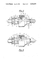
- FIG. 3 is a detailed sectional view of the engine starter device with the pinion gear engaging the ring gear to transmit torque
- FIG. 4 is a detailed sectional view of the engine starter device showing the clutch teeth of the driving member and the outer sleeve member separated when the starter gear engages the ring gear and the engine overruns the starter.
- a starter device according to the present invention is generally designated by the numeral 10.
- the starter device 10 is mounted on a power shaft 12 of a starter motor (not illustrated) which has one end 14.
- the shaft 12 further has a first outer diameter 16 and a second outer diameter 18.
- the second outer diameter 18 is larger than the first outer diameter 16.
- a radial shoulder portion 20 is formed between the first outer diameter 16 and the second outer diameter 18.
- a diametral hole 22 is formed in the second outer diameter 18 of the power shaft 12.
- An intermediate sleeve member 24 is mounted on the second outer diameter 18 of the power shaft 12.
- the intermediate sleeve member 24 has one end 26 and an opposite end 28.
- the one end 26 has a radial portion 30 or shoulder portion which extends above the periphery of the intermediate sleeve member 24.
- a pair of apertures 32 are formed through the intermediate sleeve member 24 between the one end 26 and the opposite end 28 for a purpose to be described later on herein.
- An outer sleeve member 40 is slidably mounted on the intermediate sleeve member 24.
- the outer sleeve member 40 has a first end 42 mounted adjacent the one end 26 of the intermediate sleeve member and a second end 44 opposite the first end 42.
- External helical splines 46 are formed on the outer diameter of the outer sleeve member 40.
- a counterbore 48 is formed adjacent the one end 42 on the inner diameter 50 of the outer sleeve member 40.
- the radial portion 30 of the intermediate sleeve member 24 extends into the counterbore 48.
- a biasing member 38 is disposed in the counterbore 48 so as to urge the radial portion 30 away from a shoulder 49 of the counterbore 48.
- a one way clutch tool 52 is formed on the second end 44 of the outer sleeve member 40.
- a notch 54 is formed in one of the external helical splines 46 adjacent the one end 42.
- the notch 54 is preferably milled and has a radial shoulder portion 56 and an opposite sloped shoulder portion 58 which is adjacent to the one end 42 for a purpose to be described later on herein.
- a driving sleeve member 60 is also slidably mounted on the periphery of the intermediate sleeve member 24 so as to be adjacent the outer sleeve member 40.
- the driving sleeve member 60 has one end 62 and an opposite end 64.
- the one end 62 has one way clutch teeth 66 which mutually engage the clutch teeth 52 on the outer sleeve member 40.
- annular spacer member 70 is slidably mounted in a diametral groove 41 formed near the periphery of and adjacent to the second end 44 of the outer sleeve member 40.
- the annular spacer member 70 is slidably mounted in a diametral groove 61 formed adjacent to the periphery of the driving sleeve member 60 and adjacent to the one end 62.
- the spacer member 70 is disposed above the clutch teeth 52 and 66.
- the annular spacer member 70 further has an outer diameter 72.
- the driving sleeve member 60 has a pair of slotted apertures 68 to permit the axial movement of the driving sleeve member relative to the intermediate sleeve member 24 and a retainer pin 80.
- the retainer pin 80 is mounted through the slotted apertures 68 of the driving sleeve member 60, through the pair of apertures 32 in the intermediate sleeve member 24 and the diametral hole 22 in the power shaft 12 to non-rotatably connect the driving sleeve member 60 and the intermediate sleeve member 24 to the power shaft 12.
- the driving sleeve member 60 also has a first outer diameter 63.
- the driving sleeve member 60 also has a second outer diameter 65 adjacent to the first outer diameter 63.
- the second outer diameter 65 is smaller than the first outer diameter 63 and forms a radial shoulder portion 69 therebetween.
- a retainer member 82 is slidably mounted on the second outer diameter 65 of the driving sleeve member 60.
- the retainer member 82 has an axially extending portion 84 and a radially extending portion 86.
- the axially extending portion 84 of the retainer member 82 is mounted adjacent to the radial shoulder portion 69 of the driving sleeve member 60.
- a stop member 90 is slidably mounted on the outer diameter of the intermediate sleeve member 24 adjacent to the opposite end 28.
- a diametral groove 27 is formed adjacent to the opposite end 28.
- a lock ring member 92 is disposed in the diametral groove 27 to prevent axial movement of the stop member 90 with respect to the intermediate sleeve member 24.
- the stop member 90 further has a counterbore 94 into which is disposed the lock ring member 92.
- the stop member 90 also has a radially extending portion 96.
- a helical biasing member 100 is mounted between the retainer member 82 and the stop member 90.
- the one end of the helical biasing member 100 abuts against the radially extending portion 86 and the other end of the helical biasing member abuts against the radially extending portion 96 of the stop member 90 to urge the one way clutch teeth 66 on the driving sleeve member 60 into mesh with the one way clutch teeth 52 of the outer sleeve member 40.
- a biasing member 38 urges the outer sleeve member 40 away from the radially extending portion 30 of the intermediate sleeve member 24.
- a control nut 110 slidably engages the external helical splines 46 formed on the outer sleeve member 40.
- the control nut 110 further has a plurality of radial lugs 112. One of the radial lugs is formed with a radial aperture 114 to receive a spring pressed detent 116 therein.
- the detent 116 is mounted for radial sliding movement in the control nut 110 and for bearing on the periphery of the outer sleeve member 40.
- the outer sleeve member 40 has a notch 54 which is positioned to receive the detent 116 when the control nut 110 threadably advances along the external helical splines 46 of the outer sleeve member 40.
- the outer sleeve member 40 also has an inclined shoulder 43 adjacent the one end 44 and adjacent the diametral groove 41.
- the inclined shoulder 43 and the outer diameter 72 of the annular spacer member 70 are positioned to receive the detent 116 to provide an antidrift means in order to prevent the control nut 110 from drifting away from the idle position shown in FIG. 2.
- a pinion gear 120 is slidably mounted on the first outer diameter 16 of the power shaft 12 adjacent to the one end 14 for movement into and out of mesh with the ring gear 140 of engine to be started.
- a bearing member 122 is preferably interposed between the first outer diameter 16 of the power shaft 12 and the inner diameter of the pinion gear 120.
- a barrel or enclosing cup member 130 connects the pinion gear to the control nut 110.
- the barrel member 130 has a closed end 132 which is suitably connected to the pinion gear 120 and an open end 134 which is opposite the closed end 132.
- the barrel member 130 further has a plurality of axially extending lugs 138 adjacent the open end 134 to engage the plurality of radial lugs 112 on the control nut 110.
- a cavity 128 In between the closed end 132 and the open end 134 of the barrel member 130 is formed a cavity 128. This permits the barrel member 130 to encapsulate therein the outer sleeve member 40, the control nut 110 and an annular resilient cushion member 150 therein.
- the annular resilient cushion member 150 is elastically deformable and has a plurality of slots 156 formed in its periphery to engage the axially extending lugs 138 in the barrel member 130.
- annular resilient cushion member 150 is rotatably mounted with the barrel member 130 and is interposed a radial shoulder 126 in the barrel member 130 and an annular groove 118 formed in the control nut 110 at its opposite end.
- the control nut 110 and the annular resilient cushion member 150 are prevented from moving out of the cavity 128 in the barrel member 130 by means of a lock ring 148 which is disposed in a circular groove 136.
- the lock ring 148 prevents axial movement of the control nut past the open end 134 of the barrel member 130.
- the radially extending portion 86 of the retainer member 82 abuts against the shoulder 124 of the control nut 110 and the axially extending portion 84 is interposed the control nut 110 and the driving sleeve member 60.
- the first outer diameter 16 of the power shaft 12 has an axial stop member 144 which is inserted into a circular groove 15 formed adjacent the one end 14 of the power shaft 12.
- the axial stop member 144 further has a shield member 146 which is mounted on the first outer diameter 16 of the power shaft 12 and extends axially onto the periphery of the axial stop member 144.
- the axial stop member 144 prevents the axial movement of the pinion gear 120 beyond a predetermined point and is located on the power shaft 12 in order to insure that the pinion gear 120 engages the ring gear 140 of the engine to be started.
- the driving sleeve member 60 has one way clutch teeth 66 which are connected to the mutually engaging one way clutch teeth 52 on the outer sleeve member 40 so as to rotate the outer sleeve member 40 with the power shaft 12.
- the inertia of the pinion gear 120, the barrel member 130, and the control nut 110 causes the control nut to move along the helical splines 46 to traverse the pinion gear 120 into mesh with the ring gear 140.
- the pinion gear 120 is prevented from further axial movement by virtue of the axial stop member 144 on the power shaft 12.
- the control nut 110 continues to move axially towards the axial stop member 144 and in doing so compresses the annular resilient cushion member 150.
- This movement of the control nut 110 to compress the annular resilient cushion member 150 continues until the annular resilient cushion member transmits torque from the control nut to the barrel member 130 so as to rotate the pinion gear 120.
- the further rotation of the power shaft 12 causes cranking torque to be transmitted to the ring gear 140 in order to start the engine as shown in FIG. 3.
- an indexing means is provided to rectify this condition.
- the indexing means permits the control nut 110 to be rotated on the helical splines 46 with respect to the outer sleeve member 40. In this abutting condition, the control nut 110 moves rearward, that is, towards the retainer pin 80 which causes compression of the helical biasing member 100.
- the control nut 110 is thereby rotated by traveling along the external helical splines 46 to cause the pinion gear 120 to clear the abutment with the engine ring gear 140. This permits the pinion gear 120 to mesh with the engine ring gear to start the engine.
- the acceleration of the pinion gear 120 to a predetermined speed causes the detent 116 to withdraw due to its centrifugal force from the notch 54 in outer sleeve member 40.
- the control nut 110 and the barrel traverse the power shaft 12 towards the retainer pin 80 under the influence of the biasing member 38 and deceleration of the outer sleeve member 40 so that the assembly is returned to the idle position as shown in FIG. 2.
- the undesired remeshing of the pinion gear with the enging ring gear 140 is prevented by the engagement of the detent 116 with the inclined shoulder 43 on the outer sleeve member 40.
Landscapes
- Engineering & Computer Science (AREA)
- Chemical & Material Sciences (AREA)
- Combustion & Propulsion (AREA)
- Mechanical Engineering (AREA)
- General Engineering & Computer Science (AREA)
- Connection Of Motors, Electrical Generators, Mechanical Devices, And The Like (AREA)
Abstract
Description
Claims (12)
Priority Applications (1)
| Application Number | Priority Date | Filing Date | Title |
|---|---|---|---|
| US06/409,196 US4524629A (en) | 1982-08-18 | 1982-08-18 | Compact engine starter drive |
Applications Claiming Priority (1)
| Application Number | Priority Date | Filing Date | Title |
|---|---|---|---|
| US06/409,196 US4524629A (en) | 1982-08-18 | 1982-08-18 | Compact engine starter drive |
Publications (1)
| Publication Number | Publication Date |
|---|---|
| US4524629A true US4524629A (en) | 1985-06-25 |
Family
ID=23619446
Family Applications (1)
| Application Number | Title | Priority Date | Filing Date |
|---|---|---|---|
| US06/409,196 Expired - Lifetime US4524629A (en) | 1982-08-18 | 1982-08-18 | Compact engine starter drive |
Country Status (1)
| Country | Link |
|---|---|
| US (1) | US4524629A (en) |
Cited By (11)
| Publication number | Priority date | Publication date | Assignee | Title |
|---|---|---|---|---|
| US5241871A (en) * | 1992-10-23 | 1993-09-07 | United Technologies Motor Systems, Inc. | Torque limiting starter drive clutch assembly |
| US5513540A (en) * | 1994-08-02 | 1996-05-07 | Purolator Products N.A., Inc. | Engine starter gearing having improved grease retention |
| US5806366A (en) * | 1995-09-12 | 1998-09-15 | Valeo Equipements Electriques Moteur | Starter head and a motor vehicle starter having such a head |
| WO2002035088A1 (en) * | 2000-10-25 | 2002-05-02 | Robert Bosch Gmbh | Starting device for internal combustion engines |
| US20040173038A1 (en) * | 2003-03-07 | 2004-09-09 | Tech Development, Inc. | Inertia drive torque transmission level control and engine starter incorporating same |
| US20100077769A1 (en) * | 2008-09-29 | 2010-04-01 | John Andrew Layer | Starter drive assembly and method of starting a gas turbine engine |
| US20100082218A1 (en) * | 2008-09-29 | 2010-04-01 | John Andrew Layer | Starter drive assembly and method of starting an engine |
| US20120085306A1 (en) * | 2010-10-09 | 2012-04-12 | Chu jun-jie | Starter motor |
| US20150020761A1 (en) * | 2012-05-17 | 2015-01-22 | Mitsubishi Electric Corporation | Engine startup device |
| US9726138B2 (en) * | 2014-03-12 | 2017-08-08 | Mitsubishi Electric Corporation | Engine starter |
| CN108071543A (en) * | 2016-11-16 | 2018-05-25 | 株式会社电装 | Starter |
Citations (10)
| Publication number | Priority date | Publication date | Assignee | Title |
|---|---|---|---|---|
| US2440657A (en) * | 1946-02-25 | 1948-04-27 | Bendix Aviat Corp | Engine starter drive |
| US2747414A (en) * | 1952-12-11 | 1956-05-29 | Gen Motors Corp | Starter |
| US2901912A (en) * | 1958-01-02 | 1959-09-01 | Bendix Aviat Corp | Engine starter gearing |
| US2902864A (en) * | 1958-01-02 | 1959-09-08 | Bendix Aviat Corp | Engine starter drives |
| US2922307A (en) * | 1956-09-19 | 1960-01-26 | Bendix Aviat Corp | Engine starter drives |
| US2933926A (en) * | 1960-04-26 | Engine starter drive | ||
| US2979961A (en) * | 1959-12-16 | 1961-04-18 | Bendix Corp | Engine starter drives |
| US2984115A (en) * | 1961-05-16 | Starter gearing for internal combustion engines | ||
| US2996924A (en) * | 1959-11-13 | 1961-08-22 | Bendix Corp | Starter gearing for internal combustion engines |
| US3222938A (en) * | 1964-01-08 | 1965-12-14 | Bendix Corp | Engine starter gearing |
-
1982
- 1982-08-18 US US06/409,196 patent/US4524629A/en not_active Expired - Lifetime
Patent Citations (10)
| Publication number | Priority date | Publication date | Assignee | Title |
|---|---|---|---|---|
| US2933926A (en) * | 1960-04-26 | Engine starter drive | ||
| US2984115A (en) * | 1961-05-16 | Starter gearing for internal combustion engines | ||
| US2440657A (en) * | 1946-02-25 | 1948-04-27 | Bendix Aviat Corp | Engine starter drive |
| US2747414A (en) * | 1952-12-11 | 1956-05-29 | Gen Motors Corp | Starter |
| US2922307A (en) * | 1956-09-19 | 1960-01-26 | Bendix Aviat Corp | Engine starter drives |
| US2901912A (en) * | 1958-01-02 | 1959-09-01 | Bendix Aviat Corp | Engine starter gearing |
| US2902864A (en) * | 1958-01-02 | 1959-09-08 | Bendix Aviat Corp | Engine starter drives |
| US2996924A (en) * | 1959-11-13 | 1961-08-22 | Bendix Corp | Starter gearing for internal combustion engines |
| US2979961A (en) * | 1959-12-16 | 1961-04-18 | Bendix Corp | Engine starter drives |
| US3222938A (en) * | 1964-01-08 | 1965-12-14 | Bendix Corp | Engine starter gearing |
Cited By (18)
| Publication number | Priority date | Publication date | Assignee | Title |
|---|---|---|---|---|
| US5241871A (en) * | 1992-10-23 | 1993-09-07 | United Technologies Motor Systems, Inc. | Torque limiting starter drive clutch assembly |
| US5513540A (en) * | 1994-08-02 | 1996-05-07 | Purolator Products N.A., Inc. | Engine starter gearing having improved grease retention |
| US5806366A (en) * | 1995-09-12 | 1998-09-15 | Valeo Equipements Electriques Moteur | Starter head and a motor vehicle starter having such a head |
| CN1076794C (en) * | 1995-09-12 | 2001-12-26 | 瓦莱奥电机设备公司 | Automotive starter with gearing mechanism and the gearing mechanism therefor |
| WO2002035088A1 (en) * | 2000-10-25 | 2002-05-02 | Robert Bosch Gmbh | Starting device for internal combustion engines |
| US20040173038A1 (en) * | 2003-03-07 | 2004-09-09 | Tech Development, Inc. | Inertia drive torque transmission level control and engine starter incorporating same |
| US6948392B2 (en) | 2003-03-07 | 2005-09-27 | Tech Development, Inc. | Inertia drive torque transmission level control and engine starter incorporating same |
| US20100082218A1 (en) * | 2008-09-29 | 2010-04-01 | John Andrew Layer | Starter drive assembly and method of starting an engine |
| US20100077769A1 (en) * | 2008-09-29 | 2010-04-01 | John Andrew Layer | Starter drive assembly and method of starting a gas turbine engine |
| US8014934B2 (en) | 2008-09-29 | 2011-09-06 | General Electric Company | Starter drive assembly and method of starting an engine |
| US20120085306A1 (en) * | 2010-10-09 | 2012-04-12 | Chu jun-jie | Starter motor |
| US9004035B2 (en) * | 2010-10-09 | 2015-04-14 | Johnson Electric S.A. | Starter motor |
| US20150020761A1 (en) * | 2012-05-17 | 2015-01-22 | Mitsubishi Electric Corporation | Engine startup device |
| US9670892B2 (en) * | 2012-05-17 | 2017-06-06 | Mitsubishi Electric Corporation | Engine startup device |
| US9726138B2 (en) * | 2014-03-12 | 2017-08-08 | Mitsubishi Electric Corporation | Engine starter |
| CN108071543A (en) * | 2016-11-16 | 2018-05-25 | 株式会社电装 | Starter |
| US10337482B2 (en) * | 2016-11-16 | 2019-07-02 | Denso Corporation | Starter |
| CN108071543B (en) * | 2016-11-16 | 2021-02-19 | 株式会社电装 | Starter |
Similar Documents
| Publication | Publication Date | Title |
|---|---|---|
| US4524629A (en) | Compact engine starter drive | |
| US4395923A (en) | Engine starter gearing | |
| US4020935A (en) | Direct cranking starter drive | |
| US4627299A (en) | Engine starter gearing | |
| US2933926A (en) | Engine starter drive | |
| US4744258A (en) | Non-indexing engine starter gearing | |
| US3646820A (en) | Worm drive for starter motors for internal combustion engines | |
| US4019393A (en) | Engine starter gearing | |
| US3222938A (en) | Engine starter gearing | |
| US2745289A (en) | Starter gearing for internal | |
| US2902864A (en) | Engine starter drives | |
| US2787910A (en) | Engine starter drive | |
| US3090242A (en) | Starter drive | |
| US3114270A (en) | Starter drive | |
| US2996924A (en) | Starter gearing for internal combustion engines | |
| US2235076A (en) | Starter gearing | |
| US3868858A (en) | Starter for internal combustion engines | |
| US2538300A (en) | Engine starter gearing | |
| US2815669A (en) | Engine starter gearing | |
| US3318162A (en) | Starter drive | |
| US2546948A (en) | Engine starter gearing | |
| US2447198A (en) | Starter for internal-combustion engines | |
| US2984115A (en) | Starter gearing for internal combustion engines | |
| US2752794A (en) | Engine starter gearing | |
| US2900827A (en) | Engine starter gearing |
Legal Events
| Date | Code | Title | Description |
|---|---|---|---|
| AS | Assignment |
Owner name: FACET ENTERPRISES, INCORPORATED, 7030 SOUTH YALE A Free format text: ASSIGNMENT OF ASSIGNORS INTEREST.;ASSIGNOR:DIGBY, JAMES J.;REEL/FRAME:004031/0654 Effective date: 19820820 |
|
| CC | Certificate of correction | ||
| FEPP | Fee payment procedure |
Free format text: PAYOR NUMBER ASSIGNED (ORIGINAL EVENT CODE: ASPN); ENTITY STATUS OF PATENT OWNER: LARGE ENTITY |
|
| FPAY | Fee payment |
Year of fee payment: 4 |
|
| AS | Assignment |
Owner name: PUROLATOR PRODUCTS COMPANY, OKLAHOMA Free format text: CHANGE OF NAME;ASSIGNOR:FACET ENTERPRISES, INC.;REEL/FRAME:006312/0703 Effective date: 19891128 |
|
| FEPP | Fee payment procedure |
Free format text: PETITION RELATED TO MAINTENANCE FEES FILED (ORIGINAL EVENT CODE: PMFP); ENTITY STATUS OF PATENT OWNER: LARGE ENTITY |
|
| FEPP | Fee payment procedure |
Free format text: PETITION RELATED TO MAINTENANCE FEES GRANTED (ORIGINAL EVENT CODE: PMFG); ENTITY STATUS OF PATENT OWNER: LARGE ENTITY |
|
| REMI | Maintenance fee reminder mailed | ||
| FPAY | Fee payment |
Year of fee payment: 8 |
|
| SULP | Surcharge for late payment | ||
| FP | Lapsed due to failure to pay maintenance fee |
Effective date: 19930627 |
|
| STCF | Information on status: patent grant |
Free format text: PATENTED CASE |
|
| DP | Notification of acceptance of delayed payment of maintenance fee | ||
| FEPP | Fee payment procedure |
Free format text: PAYER NUMBER DE-ASSIGNED (ORIGINAL EVENT CODE: RMPN); ENTITY STATUS OF PATENT OWNER: LARGE ENTITY Free format text: PAYOR NUMBER ASSIGNED (ORIGINAL EVENT CODE: ASPN); ENTITY STATUS OF PATENT OWNER: LARGE ENTITY |
|
| AS | Assignment |
Owner name: FACET HOLDING CO., INC., NEW YORK Free format text: ASSIGNMENT OF ASSIGNORS INTEREST;ASSIGNOR:PUROLATOR PRODUCTS COMPANY;REEL/FRAME:009737/0987 Effective date: 19990212 |