US4524591A - Lock device for chain driven vehicles - Google Patents
Lock device for chain driven vehicles Download PDFInfo
- Publication number
- US4524591A US4524591A US06/454,857 US45485782A US4524591A US 4524591 A US4524591 A US 4524591A US 45485782 A US45485782 A US 45485782A US 4524591 A US4524591 A US 4524591A
- Authority
- US
- United States
- Prior art keywords
- locking
- plate portion
- chain
- base plate
- housing
- Prior art date
- Legal status (The legal status is an assumption and is not a legal conclusion. Google has not performed a legal analysis and makes no representation as to the accuracy of the status listed.)
- Expired - Fee Related
Links
- 230000007246 mechanism Effects 0.000 claims abstract description 8
- 230000001681 protective effect Effects 0.000 claims abstract description 6
- 238000010276 construction Methods 0.000 description 7
- 230000000694 effects Effects 0.000 description 1
- HDDSHPAODJUKPD-UHFFFAOYSA-N fenbendazole Chemical compound C1=C2NC(NC(=O)OC)=NC2=CC=C1SC1=CC=CC=C1 HDDSHPAODJUKPD-UHFFFAOYSA-N 0.000 description 1
- 239000007787 solid Substances 0.000 description 1
Images


Classifications
-
- E—FIXED CONSTRUCTIONS
- E05—LOCKS; KEYS; WINDOW OR DOOR FITTINGS; SAFES
- E05B—LOCKS; ACCESSORIES THEREFOR; HANDCUFFS
- E05B67/00—Padlocks; Details thereof
- E05B67/06—Shackles; Arrangement of the shackle
- E05B67/22—Padlocks with sliding shackles, with or without rotary or pivotal movement
-
- B—PERFORMING OPERATIONS; TRANSPORTING
- B62—LAND VEHICLES FOR TRAVELLING OTHERWISE THAN ON RAILS
- B62H—CYCLE STANDS; SUPPORTS OR HOLDERS FOR PARKING OR STORING CYCLES; APPLIANCES PREVENTING OR INDICATING UNAUTHORIZED USE OR THEFT OF CYCLES; LOCKS INTEGRAL WITH CYCLES; DEVICES FOR LEARNING TO RIDE CYCLES
- B62H5/00—Appliances preventing or indicating unauthorised use or theft of cycles; Locks integral with cycles
- B62H5/08—Appliances preventing or indicating unauthorised use or theft of cycles; Locks integral with cycles preventing the drive
- B62H5/12—Appliances preventing or indicating unauthorised use or theft of cycles; Locks integral with cycles preventing the drive acting on the chain wheel or the chain
-
- E—FIXED CONSTRUCTIONS
- E05—LOCKS; KEYS; WINDOW OR DOOR FITTINGS; SAFES
- E05B—LOCKS; ACCESSORIES THEREFOR; HANDCUFFS
- E05B71/00—Locks specially adapted for bicycles, other than padlocks
-
- Y—GENERAL TAGGING OF NEW TECHNOLOGICAL DEVELOPMENTS; GENERAL TAGGING OF CROSS-SECTIONAL TECHNOLOGIES SPANNING OVER SEVERAL SECTIONS OF THE IPC; TECHNICAL SUBJECTS COVERED BY FORMER USPC CROSS-REFERENCE ART COLLECTIONS [XRACs] AND DIGESTS
- Y10—TECHNICAL SUBJECTS COVERED BY FORMER USPC
- Y10T—TECHNICAL SUBJECTS COVERED BY FORMER US CLASSIFICATION
- Y10T70/00—Locks
- Y10T70/40—Portable
- Y10T70/413—Padlocks
- Y10T70/437—Key-controlled
- Y10T70/446—Rigid shackle
- Y10T70/452—Sliding
- Y10T70/454—Removable
-
- Y—GENERAL TAGGING OF NEW TECHNOLOGICAL DEVELOPMENTS; GENERAL TAGGING OF CROSS-SECTIONAL TECHNOLOGIES SPANNING OVER SEVERAL SECTIONS OF THE IPC; TECHNICAL SUBJECTS COVERED BY FORMER USPC CROSS-REFERENCE ART COLLECTIONS [XRACs] AND DIGESTS
- Y10—TECHNICAL SUBJECTS COVERED BY FORMER USPC
- Y10T—TECHNICAL SUBJECTS COVERED BY FORMER US CLASSIFICATION
- Y10T70/00—Locks
- Y10T70/50—Special application
- Y10T70/5872—For cycles
- Y10T70/5885—Drive
Definitions
- the present invention is directed generally to the field of lock devices and more particularly to a chain lock device of the type which is adapted to engage and lock the chain of a vehicle, such as a bicycle, motorcycle, motor bike, moped or the like, to prevent rotational movement of the chain drive and hence, to minimize efforts to commit theft.
- a vehicle such as a bicycle, motorcycle, motor bike, moped or the like
- a chain lock which incorporates a main body having at one end a plate detachably secured thereto and which with the body defines a channel to receive the chain which is engaged by a pair of prongs which are secured by a manually operable lock mechanism disposed in the body.
- Such chain lock device is disclosed, for example, in U.S. Pat. No. 4,019,354.
- Other lock devices are further illustrated, for example, in U.S. Pat. Nos. 60,454, 587,456 and 3,754,420.
- the present invention provides a chain lock device and more particularly provides a new and improved chain lock device which is adapted to engage especially the master link of the chain, such as on a bicycle, motorcycle, motor bike or moped, to prevent any substantial rotational movement of the chain so that it cannot be readily driven as in the case of a theft or the like.
- the device acts to provide a considerable safe-guard to slow-up the would be thief thereby to minimize the probability of theft.
- FIG. 1 is a side elevation view i11ustrating the lock device of the present invention mounted on a chain drive of a bicycle;
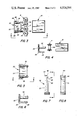
- FIG. 2 is a fragmentary, side elevation view, partly in section, on an enlarged scale illustrating the locking device of the invention in one form thereof;
- FIG. 3 is a fragmentary, side elevation view, on a reduced scale, showing the disassembled position of the lock device of the invention
- FIG. 4 is generally an assembly view looking in the direction of the line 4--4 of FIG. 3;
- FIG. 5 is a top plan view of the detachable locking plate in one form of the invention.
- FIG. 6 is an end elevation view of the locking plate illustrated in FIG. 5 and looking in the direction of the line 6--6;
- FIG. 7 is a side elevation view, on an enlarged scale, of one of the locking pin elements of the invention.
- FIG. 8 is a side elevation view looking along the line 8--8 of the pin element of FIG. 7;
- FIG. 9 is a top plan view of a modified form of the locking plate of the invention.
- FIG. 10 is a side elevation view of the locking plate of FIG. 9 looking from the left hand side thereof;
- FIG 11 is an end elevation view of the locking plate of FIG. 10 looking from the right hand side thereof;
- FIG. 12 is a rear view of the locking plate illustrated in FIG. 10;
- FIG. 13 is a bottom view of the locking plate illustrated in FIG. 9.
- FIG. 1 there is illustrated a conventional type of bicycle, designated generally at 2, which has a chasis mounted on wheels.
- the locking device of the invention, designated generally at 6, is illustrated in locking position on the drive chain 7 of the bicycle.
- the locking device 6 is constructed and arranged so as to be especially used with the master link 8 of the chain 7. That is, the link that joins the chain 7 into an endless loop construction, as known in the art.
- the locking device 6 includes an elongated, generally rectangular housing 10 which has a conventional key-lock internal mechanism which may have a conventional cylinder and tumbler construction disposed within a cavity 15 provided in the housing 10.
- the cylinder has a spring-loaded arm 12 which is rotated into and out of locking engagement with the locking plate 20 of the lock device 6.
- the arm 12 has a tapered configuration, as at 14, so as to fit within correspondingly shaped recessed slots provided in the pin elements 32 of the locking plate 20.
- the locking plate member 20 has a flat base plate portion 22 which has an integral side flange portion 24 bent at right angles thereof and extending downwardly in a direction toward the lock housing 10.
- the side plate portion is spaced laterally from the pin elements 32 and provides, in effect, a skirt portion which gives an outer protective shield for concealing the drive chain 7 in the installed position thereof.
- an outer protective skirt-like flange 24 would be seen on the outside in protective relation over the drive chain 7.
- This arrangement provides a generally L-shaped construction with the flange 24 having linear side portions 26 which merge into tapered convergent side portions 28 which, in turn, merge into a flat end edge 30 which extends parallel to the base plate 22.
- FIGS. 2 through 8 there is shown a pair of oppositely disposed pin elements 32 which extend in parallel relationship down from the base plate 22 and through openings 33 in the housing.
- the pin elements are of an elongated solid cylindrical construction having a length greater than the corresponding transverse dimension of the flange 24.
- the pin elements 32 are of an identical construction each having a recessed slot, as at 34, adjacent its end.
- Each slot 34 is defined by an inclined cam surface 36 which merges into a flat bottom surface 38 (FIG. 2) which then, in turn, merges into a flat bottom surface 40 extending at right angles thereto.
- the surface 40 then merges into an outer inclined surface 42 which extends generally parallel to the inclined surface 36 so as to provide a slide-action on the confronting inclined surface 14 of the spring-loaded pivot arm 12.
- the pin elements may terminate in a frustroconical nose portion, as at 44, to facilitate entry of the respective pin elements through the associated openings provided in the master link 8 of the drive chain 7.
- the master link as at 9, is illustrated for connecting the drive chain portions together.
- FIGS. 9 through 13 there is illustrated a modified form of the locking plate, designated generally at 50, in accordance with the invention.
- the construction is generally identical except that there is only one locking pin element but used in combination with a guide pin.
- the locking plate member 50 includes a base plate 52 with an integral depending side flange portion 54 which provides a protective skirt, as aforesaid.
- the side plate portion 54 has linear and parallel side edges 51 which merge into inclined convergent side edges 56 which merge into a bottom edge 58 (FIG. 10) that extends parallel to the base 52.
- the locking pin element 62 is of identical construction as the locking pin elements 32 in the embodiment of FIG. 2 and having the recessed slot 64 for the purposes, as aforesaid.
- an elongated cylindrical guide pin 60 is provided to have a guiding function rather than being locked by the spring-loaded arm of the lock mechanism.
- the guide element 60 extends parallel to the locking pin element 62 and has a greater length thereof so as to freely pass through the link openings and be received within the cavity of the housing.
Landscapes
- Engineering & Computer Science (AREA)
- Mechanical Engineering (AREA)
- Lock And Its Accessories (AREA)
Abstract
A lock device of the type for use for locking engagement with a drive chain of a vehicle, such as a bicycle, motorcycle, moped or the like, which includes a locking plate member having at least one elongated locking pin element and with an outer protective flange-like shield for locking and unlocking the chain upon actuation of a keylock mechanism.
Description
The present invention is directed generally to the field of lock devices and more particularly to a chain lock device of the type which is adapted to engage and lock the chain of a vehicle, such as a bicycle, motorcycle, motor bike, moped or the like, to prevent rotational movement of the chain drive and hence, to minimize efforts to commit theft.
Heretofore, there have been provided various types of bar, link and other articulated mechanisms for preventing the theft of vehicles, such as bicycles, motorcycles, motor bikes, mopeds and the like. Such devices have ranged from the very complex to the very simple such as that which is identified as bike chain locks. These locks have generally included a flexible belt, strap or chain which has an integral pad-lock mechanism for locking the free ends of the chain together so that the chain can be looped around the wheel, for example, of the vehicle and then attached around a fixed part of the vehicle frame.
More recently, there has been provided a chain lock which incorporates a main body having at one end a plate detachably secured thereto and which with the body defines a channel to receive the chain which is engaged by a pair of prongs which are secured by a manually operable lock mechanism disposed in the body. Such chain lock device is disclosed, for example, in U.S. Pat. No. 4,019,354. Other lock devices are further illustrated, for example, in U.S. Pat. Nos. 60,454, 587,456 and 3,754,420.
The present invention provides a chain lock device and more particularly provides a new and improved chain lock device which is adapted to engage especially the master link of the chain, such as on a bicycle, motorcycle, motor bike or moped, to prevent any substantial rotational movement of the chain so that it cannot be readily driven as in the case of a theft or the like. In such cases, the device acts to provide a considerable safe-guard to slow-up the would be thief thereby to minimize the probability of theft.
Other objects and advantages of the invention will become apparent as the following description proceeds when taken in conjunction with the accompanying drawings.
FIG. 1 is a side elevation view i11ustrating the lock device of the present invention mounted on a chain drive of a bicycle;
FIG. 2 is a fragmentary, side elevation view, partly in section, on an enlarged scale illustrating the locking device of the invention in one form thereof;
FIG. 3 is a fragmentary, side elevation view, on a reduced scale, showing the disassembled position of the lock device of the invention;
FIG. 4 is generally an assembly view looking in the direction of the line 4--4 of FIG. 3;
FIG. 5 is a top plan view of the detachable locking plate in one form of the invention;
FIG. 6 is an end elevation view of the locking plate illustrated in FIG. 5 and looking in the direction of the line 6--6;
FIG. 7 is a side elevation view, on an enlarged scale, of one of the locking pin elements of the invention;
FIG. 8 is a side elevation view looking along the line 8--8 of the pin element of FIG. 7;
FIG. 9 is a top plan view of a modified form of the locking plate of the invention;
FIG. 10 is a side elevation view of the locking plate of FIG. 9 looking from the left hand side thereof;
FIG 11 is an end elevation view of the locking plate of FIG. 10 looking from the right hand side thereof;
FIG. 12 is a rear view of the locking plate illustrated in FIG. 10; and,
FIG. 13. is a bottom view of the locking plate illustrated in FIG. 9.
Referring again to the drawings, and in partcular to FIG. 1 thereof, there is illustrated a conventional type of bicycle, designated generally at 2, which has a chasis mounted on wheels. The locking device of the invention, designated generally at 6, is illustrated in locking position on the drive chain 7 of the bicycle.
As illustrated in FIGS. 2 and 3, the locking device 6 is constructed and arranged so as to be especially used with the master link 8 of the chain 7. That is, the link that joins the chain 7 into an endless loop construction, as known in the art. The locking device 6 includes an elongated, generally rectangular housing 10 which has a conventional key-lock internal mechanism which may have a conventional cylinder and tumbler construction disposed within a cavity 15 provided in the housing 10. The cylinder has a spring-loaded arm 12 which is rotated into and out of locking engagement with the locking plate 20 of the lock device 6. For this purpose, the arm 12 has a tapered configuration, as at 14, so as to fit within correspondingly shaped recessed slots provided in the pin elements 32 of the locking plate 20.
As shown in FIGS. 3 through 8, the locking plate member 20 has a flat base plate portion 22 which has an integral side flange portion 24 bent at right angles thereof and extending downwardly in a direction toward the lock housing 10. The side plate portion is spaced laterally from the pin elements 32 and provides, in effect, a skirt portion which gives an outer protective shield for concealing the drive chain 7 in the installed position thereof. Accordingly, in FIG. 1 an outer protective skirt-like flange 24 would be seen on the outside in protective relation over the drive chain 7. This arrangement provides a generally L-shaped construction with the flange 24 having linear side portions 26 which merge into tapered convergent side portions 28 which, in turn, merge into a flat end edge 30 which extends parallel to the base plate 22.
Now in the invention and in the embodiment illustrated in FIGS. 2 through 8, there is shown a pair of oppositely disposed pin elements 32 which extend in parallel relationship down from the base plate 22 and through openings 33 in the housing. The pin elements are of an elongated solid cylindrical construction having a length greater than the corresponding transverse dimension of the flange 24. The pin elements 32 are of an identical construction each having a recessed slot, as at 34, adjacent its end. Each slot 34 is defined by an inclined cam surface 36 which merges into a flat bottom surface 38 (FIG. 2) which then, in turn, merges into a flat bottom surface 40 extending at right angles thereto. The surface 40 then merges into an outer inclined surface 42 which extends generally parallel to the inclined surface 36 so as to provide a slide-action on the confronting inclined surface 14 of the spring-loaded pivot arm 12. The pin elements may terminate in a frustroconical nose portion, as at 44, to facilitate entry of the respective pin elements through the associated openings provided in the master link 8 of the drive chain 7.
In FIGS. 3 and 4 the master link, as at 9, is illustrated for connecting the drive chain portions together.
In FIGS. 9 through 13 there is illustrated a modified form of the locking plate, designated generally at 50, in accordance with the invention. In this arrangement, the construction is generally identical except that there is only one locking pin element but used in combination with a guide pin. In this embodiment, the locking plate member 50 includes a base plate 52 with an integral depending side flange portion 54 which provides a protective skirt, as aforesaid. The side plate portion 54 has linear and parallel side edges 51 which merge into inclined convergent side edges 56 which merge into a bottom edge 58 (FIG. 10) that extends parallel to the base 52. In this form, the locking pin element 62 is of identical construction as the locking pin elements 32 in the embodiment of FIG. 2 and having the recessed slot 64 for the purposes, as aforesaid. In this form, an elongated cylindrical guide pin 60 is provided to have a guiding function rather than being locked by the spring-loaded arm of the lock mechanism. For this purpose, the guide element 60 extends parallel to the locking pin element 62 and has a greater length thereof so as to freely pass through the link openings and be received within the cavity of the housing.
Other further advantages and objects of the present invention will become apparent when taken in conjunction with the accompaying claims.
Claims (2)
1. A locking device of the type adapted to engage the links of a drive chain of a vehicle, such as a bicycle, motorcycle, moped of the like, comprising a lock mechanism having a hollow housing mounting a key actuated tumbler means having a locking arm means adapted to be moved between a locked and an unlocked position, said housing having a pair of oppositely disposed openings adapted to provide ingress and egress into the housing, a locking plate member including a flat base plate portion and an integral downwardly depending side plate portion defining an L-shaped configuration in side elevation providing a protective outer skirt, at least one elongated locking pin element made integral with and extending downwardly from said base plate portion and parallel to said side plate portion and spaced laterally from said side plate portion, said locking pin element having a recessed slot adapted to receive therein the confronting end portion of said locking arm of said lock mechanism.
2. A locking device in accordance with claim 1, wherein said locking plate member includes a pair of locking pin elements extending downwardly and in parallel relationship from said base plate portion.
Priority Applications (1)
| Application Number | Priority Date | Filing Date | Title |
|---|---|---|---|
| US06/454,857 US4524591A (en) | 1982-12-30 | 1982-12-30 | Lock device for chain driven vehicles |
Applications Claiming Priority (1)
| Application Number | Priority Date | Filing Date | Title |
|---|---|---|---|
| US06/454,857 US4524591A (en) | 1982-12-30 | 1982-12-30 | Lock device for chain driven vehicles |
Publications (1)
| Publication Number | Publication Date |
|---|---|
| US4524591A true US4524591A (en) | 1985-06-25 |
Family
ID=23806377
Family Applications (1)
| Application Number | Title | Priority Date | Filing Date |
|---|---|---|---|
| US06/454,857 Expired - Fee Related US4524591A (en) | 1982-12-30 | 1982-12-30 | Lock device for chain driven vehicles |
Country Status (1)
| Country | Link |
|---|---|
| US (1) | US4524591A (en) |
Cited By (16)
| Publication number | Priority date | Publication date | Assignee | Title |
|---|---|---|---|---|
| US4823568A (en) * | 1985-06-24 | 1989-04-25 | Rogers Kermett A | Anti-theft apparatus for a riding saddle |
| US5010746A (en) * | 1990-04-25 | 1991-04-30 | Kryptonite Corporation | Bicycle lock |
| US5694796A (en) * | 1995-03-30 | 1997-12-09 | Couillard; Richard Alexander | Hinged lock with detent positions |
| US5864958A (en) * | 1997-02-10 | 1999-02-02 | Bruno Kolb | Rear sight for bow |
| WO1999000567A3 (en) * | 1997-05-12 | 1999-03-25 | Brighton Barry David | Padlocks and padlock accessories |
| US6581661B1 (en) | 1999-07-10 | 2003-06-24 | Large Car Equipment And Apparel, Llc | Apparatus for improving tire traction |
| US6718802B2 (en) * | 2002-09-05 | 2004-04-13 | Robert A. Vito | Tamper resistant lock |
| US20050100398A1 (en) * | 2003-11-10 | 2005-05-12 | Rice John R. | Flexible drive member attachment |
| US9523231B2 (en) | 2003-11-10 | 2016-12-20 | Strattec Power Access Llc | Attachment assembly and drive unit having same |
| FR3062635A1 (en) * | 2017-02-06 | 2018-08-10 | Jcdecaux Sa | ANTI-THEFT DEVICE FOR A CHAIN TRANSMISSION CYCLE |
| US10577833B1 (en) * | 2018-08-10 | 2020-03-03 | Schlage Lock Company Llc | Compact bike lock |
| US20210284265A1 (en) * | 2020-03-16 | 2021-09-16 | Daniel Otterstrom | System and method for locking a bicycle chain |
| US20230417082A1 (en) * | 2020-11-26 | 2023-12-28 | ABUS August Bremicker Söhne KG | Chain lock and chain for a chain lock |
| US12291897B2 (en) * | 2022-03-25 | 2025-05-06 | ABUS August Bremicker Söhne KG | Chain lock |
| US20250297495A1 (en) * | 2024-02-23 | 2025-09-25 | Aba Locks International Co., Ltd. | Bicycle lock |
| US12447933B2 (en) | 2021-08-19 | 2025-10-21 | Vincent C. Cook | Chain or belt drive lock |
Citations (1)
| Publication number | Priority date | Publication date | Assignee | Title |
|---|---|---|---|---|
| US1461725A (en) * | 1918-07-18 | 1923-07-17 | Thomas C Cooper | Lock |
-
1982
- 1982-12-30 US US06/454,857 patent/US4524591A/en not_active Expired - Fee Related
Patent Citations (1)
| Publication number | Priority date | Publication date | Assignee | Title |
|---|---|---|---|---|
| US1461725A (en) * | 1918-07-18 | 1923-07-17 | Thomas C Cooper | Lock |
Cited By (20)
| Publication number | Priority date | Publication date | Assignee | Title |
|---|---|---|---|---|
| US4823568A (en) * | 1985-06-24 | 1989-04-25 | Rogers Kermett A | Anti-theft apparatus for a riding saddle |
| US5010746A (en) * | 1990-04-25 | 1991-04-30 | Kryptonite Corporation | Bicycle lock |
| US5092142A (en) * | 1990-04-25 | 1992-03-03 | Kryptonite Corporation | Bicycle lock |
| US5694796A (en) * | 1995-03-30 | 1997-12-09 | Couillard; Richard Alexander | Hinged lock with detent positions |
| US5864958A (en) * | 1997-02-10 | 1999-02-02 | Bruno Kolb | Rear sight for bow |
| WO1999000567A3 (en) * | 1997-05-12 | 1999-03-25 | Brighton Barry David | Padlocks and padlock accessories |
| US6581661B1 (en) | 1999-07-10 | 2003-06-24 | Large Car Equipment And Apparel, Llc | Apparatus for improving tire traction |
| US6718802B2 (en) * | 2002-09-05 | 2004-04-13 | Robert A. Vito | Tamper resistant lock |
| US9523231B2 (en) | 2003-11-10 | 2016-12-20 | Strattec Power Access Llc | Attachment assembly and drive unit having same |
| US7297082B2 (en) * | 2003-11-10 | 2007-11-20 | Delphi Technologies, Inc. | Flexible drive member attachment |
| US20050100398A1 (en) * | 2003-11-10 | 2005-05-12 | Rice John R. | Flexible drive member attachment |
| FR3062635A1 (en) * | 2017-02-06 | 2018-08-10 | Jcdecaux Sa | ANTI-THEFT DEVICE FOR A CHAIN TRANSMISSION CYCLE |
| US10577833B1 (en) * | 2018-08-10 | 2020-03-03 | Schlage Lock Company Llc | Compact bike lock |
| US11214987B2 (en) | 2018-08-10 | 2022-01-04 | Schlage Lock Company Llc | Compact bike lock |
| US20210284265A1 (en) * | 2020-03-16 | 2021-09-16 | Daniel Otterstrom | System and method for locking a bicycle chain |
| US20230417082A1 (en) * | 2020-11-26 | 2023-12-28 | ABUS August Bremicker Söhne KG | Chain lock and chain for a chain lock |
| US12359471B2 (en) * | 2020-11-26 | 2025-07-15 | ABUS August Bremicker Söhne KG | Chain lock and chain for a chain lock |
| US12447933B2 (en) | 2021-08-19 | 2025-10-21 | Vincent C. Cook | Chain or belt drive lock |
| US12291897B2 (en) * | 2022-03-25 | 2025-05-06 | ABUS August Bremicker Söhne KG | Chain lock |
| US20250297495A1 (en) * | 2024-02-23 | 2025-09-25 | Aba Locks International Co., Ltd. | Bicycle lock |
Similar Documents
| Publication | Publication Date | Title |
|---|---|---|
| US4524591A (en) | Lock device for chain driven vehicles | |
| US4114409A (en) | Lock assembly for bicycle wheel quick release mechanism | |
| US5265451A (en) | Motorcycle lock | |
| US3858419A (en) | Two-part protective cover for padlocks | |
| US4019354A (en) | Motorcycle chain lock | |
| US5823025A (en) | Lock system with a lock-out safety device for wheeled vehicles | |
| EP0471748B1 (en) | Bicycle accessory for carrying a shackle | |
| EP0701933B1 (en) | Antitheft device for locking the steering wheel of any kind of vehicle | |
| US4825670A (en) | Vehicle shift and radio security lock device | |
| US3863767A (en) | Bicycle security rack | |
| US6112560A (en) | Track lock for snowmobiles | |
| US6698257B2 (en) | Motorcycle helmet lock using front fork lock | |
| US2575401A (en) | Safety lock device | |
| US20030066320A1 (en) | Anti-theft device for a vehicle with a handle mounted actuator | |
| US4549417A (en) | Lock for cycles | |
| US5440907A (en) | Steering wheel lock assembly with a removable cylinder | |
| US4803857A (en) | Bicycle air pump restraining device | |
| US5730012A (en) | Bicycle sprocket lock | |
| WO1995003206A1 (en) | Anti-theft device for bicycle | |
| GB1564841A (en) | Anti-theft helmet for the use of a driver or passenger of a two-wheeled vehicle | |
| US6434979B1 (en) | Vehicle clutch locking device | |
| CN220923989U (en) | Rear wheel fixing device of vehicle-mounted bicycle frame | |
| KR960002304Y1 (en) | Helmet with anti-theft lock and release | |
| ITTO20010094A1 (en) | BURGLAR ALARM DEVICE FOR MOTORCYCLE. | |
| EP0895925A1 (en) | Antitheft device for motor vehicles with accelerator in the handgrip of the handlebar |
Legal Events
| Date | Code | Title | Description |
|---|---|---|---|
| FEPP | Fee payment procedure |
Free format text: PAYOR NUMBER ASSIGNED (ORIGINAL EVENT CODE: ASPN); ENTITY STATUS OF PATENT OWNER: SMALL ENTITY |
|
| REMI | Maintenance fee reminder mailed | ||
| LAPS | Lapse for failure to pay maintenance fees | ||
| STCH | Information on status: patent discontinuation |
Free format text: PATENT EXPIRED DUE TO NONPAYMENT OF MAINTENANCE FEES UNDER 37 CFR 1.362 |
|
| FP | Lapsed due to failure to pay maintenance fee |
Effective date: 19890625 |