US4520332A - Solenoid with internally located switch contacts - Google Patents
Solenoid with internally located switch contacts Download PDFInfo
- Publication number
- US4520332A US4520332A US06/517,072 US51707283A US4520332A US 4520332 A US4520332 A US 4520332A US 51707283 A US51707283 A US 51707283A US 4520332 A US4520332 A US 4520332A
- Authority
- US
- United States
- Prior art keywords
- movable
- core
- electromagnet
- coil
- fixed
- Prior art date
- Legal status (The legal status is an assumption and is not a legal conclusion. Google has not performed a legal analysis and makes no representation as to the accuracy of the status listed.)
- Expired - Fee Related
Links
- 238000004804 winding Methods 0.000 claims abstract description 19
- 230000005284 excitation Effects 0.000 claims abstract description 6
- 238000006073 displacement reaction Methods 0.000 description 3
- XEEYBQQBJWHFJM-UHFFFAOYSA-N Iron Chemical compound [Fe] XEEYBQQBJWHFJM-UHFFFAOYSA-N 0.000 description 2
- 238000010276 construction Methods 0.000 description 2
- 238000012423 maintenance Methods 0.000 description 2
- 230000006866 deterioration Effects 0.000 description 1
- 238000010586 diagram Methods 0.000 description 1
- 229910052742 iron Inorganic materials 0.000 description 1
- 238000000465 moulding Methods 0.000 description 1
- 238000013021 overheating Methods 0.000 description 1
- 229920003023 plastic Polymers 0.000 description 1
- 239000004033 plastic Substances 0.000 description 1
- 229910052709 silver Inorganic materials 0.000 description 1
- 239000004332 silver Substances 0.000 description 1
Images

Classifications
-
- H—ELECTRICITY
- H01—ELECTRIC ELEMENTS
- H01H—ELECTRIC SWITCHES; RELAYS; SELECTORS; EMERGENCY PROTECTIVE DEVICES
- H01H50/00—Details of electromagnetic relays
- H01H50/54—Contact arrangements
- H01H50/56—Contact spring sets
- H01H50/58—Driving arrangements structurally associated therewith; Mounting of driving arrangements on armature
Definitions
- the present invention relates to an electromagnet.
- the present invention relates to an electromagnet of the type comprising an excitation coil wound as a solenoid and having at least two windings (driving and holding windings) and which can be selectively energised, a core fixedly mounted with respect to the coil, a movable core which can move axially with respect to the coil, a movable core which can move axially with respect to the said coil, and an electric switch which can be actuated by the movable core to supply the windings of the coil selectively.
- Electromagnets of the above specified type are widely used, especially in the industrial field, for transmitting displacement commands both in traction and in thrust with forces of the order of units or tens of kilograms.
- the use of the switch permits the excitation current in the coil to be reduced at the end of the stroke of the movable coil, that is when the electromagnet is in a condition where it only needs to exert a holding force; this arrangement allows, in particular, considerable forces to be obtained in traction or thrust phase whilst eliminating overheating of the coil in that at the end of the stroke the driving winding is put in series with the so-called holding winding by means of the switch and the current is drastically reduced.
- the movable core can be provided at the opposite ends with two shafts which conveniently extend out from the body of the electromagnet and which allow this latter to be used both as a thrust electromagnet as well as a pulling electromagnet.
- electromagnets provided with switches for division of the electrical supply to the coil and at the same time able to operate in pull and in push mode.
- electromagnets which function in pull mode are known, in which the switch is mounted externally and is substantially constituted by a microswitch of the end-of-stroke type, the operating push-button of which is pressed by the movable core of the electromagnet.
- This microswitch as well as being bulky, is also of low reliability in that being controlled indirectly by the movable core its electrical contacts open and close slowly causing the occurrence of spark phenomena between these latter and a consequent rapid deterioration.
- Such electromagnets of known type therefore require constant maintenance and do not lend themselves to being equally used as push and pull electromagnets, the microswitch being head mounted above the movable core.
- the object of the present invention is to provide an electromagnet of the above specified type which overcomes the disadvantages of the known electromagnets listed above.
- an electromagnet of the type comprising an excitation coil wound as a solenoid and having at least two windings which can be supplied selectively, a fixed core fixedly mounted with respect to the said coil, a movable core movable axially with respect to said coil and an electrical switch which can be operated by said movable core; first and second shafts extending from opposite axial ends of said movable core, a piston having an axial through hole surrounding said second shaft and axially slidable relative to said fixed core under the action of said movable core, an annular flange on said piston, said switch including a plurality of movable contacts riveted to an annular conductive plate fixed to said flange, and said switch further including a plurality of fixed contacts mounted rigidly with respect to said fixed core.
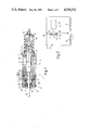
- FIG. 1 is a longitudinal, sectional view of an electromagnet formed according to the principles of the present invention
- FIG. 2 is an circuit diagram of the electromagnet of FIG. 1;
- FIG. 3 is a view on an enlarged scale of a detail of FIG. 1;
- FIGS. 4 and 5 are sectional views taken on the lines IV--IV and V--V of FIG. 3.
- an electromagnet comprising an excitation coil 2 wound as a solenoid about a former 3, a core generally indicated 4 and fixedly mounted with respect to the coil 2, a movable core 5 which can move axially with respect to the coil 2, and an electric switch generally indicated 6 and which can be actuated by the movable core 5 when this latter is pressed into contact with the fixed core 6.
- the electromagnet 1 is illustrated in FIG. 2 in which it can be seen that the coil 2 has two windings, respectively a driving winding 8 and a holding winding 9, the second of which is connected in parallel to the switch 6 and with this latter is connected in series with the first winding 8.
- Two supply terminals are generally indicated 11 and 12, these being conveniently formed by suitable flat connectors as indicated in FIG. 4.
- the switch 6 includes a pair of fixed contacts 13, 14 with which cooperate corresponding movable contacts 15, 16 which are connected together by a suitable conductive plate 17.
- the fixed contacts 13, 14 and movable contacts 15, 16 are conveniently formed by conductive projections suitably riveted onto conductive plates 23, 24 as far as the contacts 13 and 14 are concerned and onto an annular plate 17 as far as the movable contacts 15, 16 are concerned.
- Both the plate 17 and the plates 23 and 24 are fixed to corresponding support elements 18 and 19 by suitable riveted pins 20, 21, and 22 (see FIGS. 3,4 and 5).
- the fixed core 4 is substantially constituted by a cup-shape body 26 having at the lower end a bottom wall 27 through which the movable core 5 slides.
- the fixed core 4 is closed by means of a disc 28 having a tubular projection 29 extending axially inwardly and operable to act as a stop element for axial displacements of the movable core 5 into the coil 2.
- the movable core 5 has a cylindrical intermediate portion 31 which at the opposite ends is connected to threaded shafts 32, 33.
- the shaft is that which extends on the same side of the bottom wall 27 as the fixed core 4 and in a first part is protected by a bellows 34 having an end coupled to a flange 36 extending outwardly from the bottom wall 27 of the fixed core 4.
- the shaft 33 is slidable within an axially pierced piston 37 which in turn slides within the tubular projection 29 of the fixed core 4.
- this has, in particular, a first portion 38 slidable, as already mentioned within the tubular projection 29 of the fixed core 4, an intermediate portion 39 which is slidable substantially within the element 19 which supports the fixed contacts of the switch 6, a flange portion already indicated at 18 and constituting the support element for the movable contacts of the switch 6, and a head portion 40.
- This latter serves the function of guiding and positioning a cylindrical spring 41 which is thus compressed between the flange element 18 and a bottom wall 42 of a cup-shape cover 43 which encloses the switch 6.
- This cup-shape cover 43 has a through hole 45 with or without bushes to allow the passage of the shaft 33 of the movable core 5 and is connected to the disc 28 of the fixed core 4 by suitable set screws 46.
- the fixed core 4 and at least the intermediate portion 31 of the movable core 5 are made of iron only for magnetic purposes, whilst the support element 19, the piston 37 and the cover 43 are conveniently made by a plastics moulding operation.
- the outer diameters of the tubular projection 29, the fixed core 4, the portion 38 of the piston 37 and a disc 28 of the fixed core 4 are respectively indicated 47, 48, 49 and 50, 51, 52 for three different dimensions of the electromagnet 1, the upper part of the electromagnet in which the switch 6 is housed remaining the same.
- the electromagnet 1 In rest conditions the electromagnet 1 is as indicated in broken outline in FIG. 1: in particular, the switch 6 is closed in that the cylindrical spring 41 presses the piston 37 in such a way as to hold electrically connected together the electrical contacts 13 and 15 and 14 and 16 respectively of this switch.
- the supply of an electrical current to the terminals 11 and 12 initially causes the flow of current only in the driving winding 8 of the coil 2 (see FIG. 2) in that the switch 6 short circuits the holding winding 9.
- the circulation of current in the coil 2 however causes the movable core 5 to be drawn by the fixed core 4 with corresponding axial translation of the core 5 with respect to the coil 2. This translation involves, at the end of the stroke, the axial displacement of the piston 37 with consequent opening of the contacts of the switch 6.
- the electrical current now also flows into the winding 9 which is located in series with the winding 8; the current is now significantly reduced with respect to the current which was flowing only in the winding 8 and is, however, sufficient to exercise a holding action there being no longer an air gap between the fixed and movable cores 4 and 5.
- a further important advantage connected with the particular structure of the switch 6 lies in the fact that all of the parts of the electromagnet enclosed within the cup-shape cover 43 can be equally utilised in the construction of electromagnets of any dimensions, as indicated in FIG. 3; in fact, from one case to another it is sufficient to remove a desired layer of the portion 38 of the piston 37 to adapt this latter to the form of the fixed core of the corresponding electromagnet.
- the electromagnet 1 has a particularly robust and compact form and can therefore be used even in those applications in which such requirements are a determining factor.
Landscapes
- Physics & Mathematics (AREA)
- Electromagnetism (AREA)
- Electromagnets (AREA)
Abstract
Description
Claims (7)
Applications Claiming Priority (2)
| Application Number | Priority Date | Filing Date | Title |
|---|---|---|---|
| IT53584/82[U] | 1982-07-29 | ||
| IT5358482 | 1982-07-29 |
Publications (1)
| Publication Number | Publication Date |
|---|---|
| US4520332A true US4520332A (en) | 1985-05-28 |
Family
ID=11283871
Family Applications (1)
| Application Number | Title | Priority Date | Filing Date |
|---|---|---|---|
| US06/517,072 Expired - Fee Related US4520332A (en) | 1982-07-29 | 1983-07-25 | Solenoid with internally located switch contacts |
Country Status (1)
| Country | Link |
|---|---|
| US (1) | US4520332A (en) |
Cited By (2)
| Publication number | Priority date | Publication date | Assignee | Title |
|---|---|---|---|---|
| US4983941A (en) * | 1988-11-24 | 1991-01-08 | Mitsubishi Denki Kabushiki Kaisha | Electromagnetically operated switch |
| US5280260A (en) * | 1992-08-13 | 1994-01-18 | Eaton Corporation | Rotary solenoid utilizing concurrently energized AC and DC coils |
Citations (4)
| Publication number | Priority date | Publication date | Assignee | Title |
|---|---|---|---|---|
| US2344178A (en) * | 1941-11-06 | 1944-03-14 | Honeywell Regulator Co | Electromagnetic device |
| US2472553A (en) * | 1940-03-11 | 1949-06-07 | Teco Sa | Electromagnet |
| US3425009A (en) * | 1965-09-10 | 1969-01-28 | Dynatron Inc | Electro-mechanical actuator |
| US4044322A (en) * | 1976-07-09 | 1977-08-23 | Essex Group, Inc. | Electromagnetic solenoid relay assembly and electrical connection means therefor |
-
1983
- 1983-07-25 US US06/517,072 patent/US4520332A/en not_active Expired - Fee Related
Patent Citations (4)
| Publication number | Priority date | Publication date | Assignee | Title |
|---|---|---|---|---|
| US2472553A (en) * | 1940-03-11 | 1949-06-07 | Teco Sa | Electromagnet |
| US2344178A (en) * | 1941-11-06 | 1944-03-14 | Honeywell Regulator Co | Electromagnetic device |
| US3425009A (en) * | 1965-09-10 | 1969-01-28 | Dynatron Inc | Electro-mechanical actuator |
| US4044322A (en) * | 1976-07-09 | 1977-08-23 | Essex Group, Inc. | Electromagnetic solenoid relay assembly and electrical connection means therefor |
Cited By (2)
| Publication number | Priority date | Publication date | Assignee | Title |
|---|---|---|---|---|
| US4983941A (en) * | 1988-11-24 | 1991-01-08 | Mitsubishi Denki Kabushiki Kaisha | Electromagnetically operated switch |
| US5280260A (en) * | 1992-08-13 | 1994-01-18 | Eaton Corporation | Rotary solenoid utilizing concurrently energized AC and DC coils |
Similar Documents
| Publication | Publication Date | Title |
|---|---|---|
| US6870454B1 (en) | Linear switch actuator | |
| US5365210A (en) | Latching solenoid with manual override | |
| KR20000066561A (en) | Switch using uni-solenoid | |
| US2503243A (en) | Electrodynamic relay | |
| KR102330627B1 (en) | A medium voltage contactor | |
| JP2016207638A (en) | Magnetic switch | |
| US4520332A (en) | Solenoid with internally located switch contacts | |
| US4503411A (en) | Dual plunger solenoid device | |
| EP1619707A1 (en) | A medium voltage vacuum contactor | |
| US4851801A (en) | Microwave C-switches and S-switches | |
| JP6726871B2 (en) | Electromagnetic relay | |
| US4559511A (en) | Vacuum contactor having DC electromagnet with improved force watts ratio | |
| US4309683A (en) | Electric control device | |
| US2167588A (en) | Electromagnetically operated switch | |
| US2640890A (en) | Multipositioned liquid switch | |
| US3130282A (en) | Solenoid operated switches | |
| US1209646A (en) | Electromagnet. | |
| KR100770762B1 (en) | Low power consumption type magnetic contactor | |
| CN213093070U (en) | Action mechanism and switching device | |
| US2790876A (en) | Relay | |
| IE47781B1 (en) | Contactor | |
| US3244834A (en) | Electromagnetic miniature relay | |
| KR102770711B1 (en) | magnetic contactor | |
| US3200220A (en) | Combination electrical socket, electromagnetic actuator and on-off switch | |
| US3414852A (en) | Magnetic latching relay |
Legal Events
| Date | Code | Title | Description |
|---|---|---|---|
| AS | Assignment |
Owner name: COSTRUZIONI ELETTROMAGNETICHE INDUSTRIALI DI TAGLI Free format text: ASSIGNMENT OF ASSIGNORS INTEREST.;ASSIGNOR:TAGLIAFICO, CARLO;REEL/FRAME:004159/0253 Effective date: 19830630 Owner name: COSTRUZIONI ELETTROMAGNETICHE INDUSTRIALI DI TAGLI Free format text: ASSIGNMENT OF ASSIGNORS INTEREST;ASSIGNOR:TAGLIAFICO, CARLO;REEL/FRAME:004159/0253 Effective date: 19830630 |
|
| FEPP | Fee payment procedure |
Free format text: PAYOR NUMBER ASSIGNED (ORIGINAL EVENT CODE: ASPN); ENTITY STATUS OF PATENT OWNER: SMALL ENTITY |
|
| FPAY | Fee payment |
Year of fee payment: 4 |
|
| AS | Assignment |
Owner name: C.E.I. COSTRUZIONI ELETTROMAGNETICHE INDUSTRIALI S Free format text: CHANGE OF NAME;ASSIGNOR:COSTRUZIONI ELETTROMAGNETICHE INDUSTRIALI DI TAGLIAFICO CARLO;REEL/FRAME:005681/0662 Effective date: 19910306 |
|
| LAPS | Lapse for failure to pay maintenance fees | ||
| FP | Lapsed due to failure to pay maintenance fee |
Effective date: 19930530 |
|
| STCH | Information on status: patent discontinuation |
Free format text: PATENT EXPIRED DUE TO NONPAYMENT OF MAINTENANCE FEES UNDER 37 CFR 1.362 |