US4518904A - Stepper motor control for data disk system - Google Patents
Stepper motor control for data disk system Download PDFInfo
- Publication number
- US4518904A US4518904A US06/573,708 US57370884A US4518904A US 4518904 A US4518904 A US 4518904A US 57370884 A US57370884 A US 57370884A US 4518904 A US4518904 A US 4518904A
- Authority
- US
- United States
- Prior art keywords
- current
- stepper motor
- signal
- control
- rotor
- Prior art date
- Legal status (The legal status is an assumption and is not a legal conclusion. Google has not performed a legal analysis and makes no representation as to the accuracy of the status listed.)
- Expired - Fee Related
Links
- 238000013500 data storage Methods 0.000 claims abstract description 6
- 230000033001 locomotion Effects 0.000 claims description 33
- 238000000926 separation method Methods 0.000 claims description 9
- 238000001514 detection method Methods 0.000 claims description 7
- 230000004044 response Effects 0.000 claims description 7
- 230000010355 oscillation Effects 0.000 claims description 5
- 230000000284 resting effect Effects 0.000 claims description 2
- 230000003247 decreasing effect Effects 0.000 claims 1
- 230000007246 mechanism Effects 0.000 abstract description 34
- 238000004804 winding Methods 0.000 description 43
- 238000010586 diagram Methods 0.000 description 12
- 230000001965 increasing effect Effects 0.000 description 7
- 238000000034 method Methods 0.000 description 7
- 238000012937 correction Methods 0.000 description 6
- 230000002829 reductive effect Effects 0.000 description 4
- 230000001133 acceleration Effects 0.000 description 3
- 238000013459 approach Methods 0.000 description 3
- 230000008901 benefit Effects 0.000 description 3
- 230000008859 change Effects 0.000 description 3
- 238000013016 damping Methods 0.000 description 3
- 230000009021 linear effect Effects 0.000 description 3
- 230000003044 adaptive effect Effects 0.000 description 2
- 230000000694 effects Effects 0.000 description 2
- 230000002708 enhancing effect Effects 0.000 description 2
- 239000002184 metal Substances 0.000 description 2
- 229910052751 metal Inorganic materials 0.000 description 2
- 230000008569 process Effects 0.000 description 2
- 230000009467 reduction Effects 0.000 description 2
- 240000006829 Ficus sundaica Species 0.000 description 1
- 230000006399 behavior Effects 0.000 description 1
- 230000003111 delayed effect Effects 0.000 description 1
- 230000001419 dependent effect Effects 0.000 description 1
- 238000011161 development Methods 0.000 description 1
- 230000018109 developmental process Effects 0.000 description 1
- 230000008030 elimination Effects 0.000 description 1
- 238000003379 elimination reaction Methods 0.000 description 1
- 238000002474 experimental method Methods 0.000 description 1
- 230000006870 function Effects 0.000 description 1
- 230000006872 improvement Effects 0.000 description 1
- 230000009022 nonlinear effect Effects 0.000 description 1
- 230000002093 peripheral effect Effects 0.000 description 1
- 230000002441 reversible effect Effects 0.000 description 1
- 238000012163 sequencing technique Methods 0.000 description 1
- 230000035939 shock Effects 0.000 description 1
- 230000003068 static effect Effects 0.000 description 1
- 230000036962 time dependent Effects 0.000 description 1
- 238000012546 transfer Methods 0.000 description 1
Images


Classifications
-
- H—ELECTRICITY
- H02—GENERATION; CONVERSION OR DISTRIBUTION OF ELECTRIC POWER
- H02P—CONTROL OR REGULATION OF ELECTRIC MOTORS, ELECTRIC GENERATORS OR DYNAMO-ELECTRIC CONVERTERS; CONTROLLING TRANSFORMERS, REACTORS OR CHOKE COILS
- H02P8/00—Arrangements for controlling dynamo-electric motors rotating step by step
-
- G—PHYSICS
- G11—INFORMATION STORAGE
- G11B—INFORMATION STORAGE BASED ON RELATIVE MOVEMENT BETWEEN RECORD CARRIER AND TRANSDUCER
- G11B21/00—Head arrangements not specific to the method of recording or reproducing
- G11B21/02—Driving or moving of heads
- G11B21/08—Track changing or selecting during transducing operation
- G11B21/081—Access to indexed tracks or parts of continuous track
- G11B21/083—Access to indexed tracks or parts of continuous track on discs
- G11B21/085—Access to indexed tracks or parts of continuous track on discs with track following of accessed part
-
- G—PHYSICS
- G11—INFORMATION STORAGE
- G11B—INFORMATION STORAGE BASED ON RELATIVE MOVEMENT BETWEEN RECORD CARRIER AND TRANSDUCER
- G11B5/00—Recording by magnetisation or demagnetisation of a record carrier; Reproducing by magnetic means; Record carriers therefor
- G11B5/48—Disposition or mounting of heads or head supports relative to record carriers ; arrangements of heads, e.g. for scanning the record carrier to increase the relative speed
- G11B5/54—Disposition or mounting of heads or head supports relative to record carriers ; arrangements of heads, e.g. for scanning the record carrier to increase the relative speed with provision for moving the head into or out of its operative position or across tracks
- G11B5/55—Track change, selection or acquisition by displacement of the head
- G11B5/5521—Track change, selection or acquisition by displacement of the head across disk tracks
- G11B5/5526—Control therefor; circuits, track configurations or relative disposition of servo-information transducers and servo-information tracks for control thereof
- G11B5/553—Details
Definitions
- the present invention relates to a data disk storage system utilizing a stepper motor for controlling the movement of a read/write head across the tracks of the data disk.
- stepper motors otherwise sometimes referred to as impulse motors
- the rotor of the motor is incrementally moved through a series of discrete movements or steps as a result of a corresponding number of discrete changes in the energization of the windings of the stator of the motor.
- an incremental drive force is generated for driving the rotor in the series of incremental steps.
- the energy supplied to the stator windings creates an internal magnetic field which generates a torque that urges the rotor to assume a mechanical position in line with the resultant magnetic field.
- a control mechanism commonly has been utilized for doubling the possible number of discrete positions or steps, that the output shaft can adopt. This doubling operation is accomplished by alternately passing current through both windings simultaneously and then through only one winding. The angle through which the motor shaft moves for each of these current changes is equal to one half of one motor step. Examples of such half step control systems are disclosed in U.S. Pat. Nos. 3,077,555 to Fredrickson and No. 3,746,958 to Leenhouts.
- stepper motor control systems Numerous other stepper motor control systems have been developed primarily for increasing the number of steps within each motor cycle and additionally some attempt has been made for developing sophisticated control systems for overcoming the problems associated with the unequal torque applied to the rotor during the stepping operation. Exemplary of such developments are the various stepper motor control systems disclosed in those U.S. patents discussed below.
- U.S. Pat. No. 3,445,741 to Gerber discloses a stepper motor in which each full step is broken down into a large number of smaller or fractional steps by varying the energization of the stator winding between a number of levels, which includes one or more levels in addition to 0,+1 unit levels.
- the control unit utilized in conjunction with the stepper motor disclosed by this patent to Gerber controls the current flowing through each of the stator windings for providing the additional current level.
- U.S. Pat. No. 3,800,206 to Hinachi et al. discloses a drive control system for a 4-phase stepping motor.
- the number of steps for the rotor is increased by alternately energizing one coil and then a pair of coils of the stator windings. Uniformity of the resulting torque which would be inherent with such an energization system is avoided by increasing the exciting current during a time when one phase coil along is excited so as to be larger than the exciting current per phase during a time when 2-phase coils are excited.
- U.S. Pat. No. 3,728,598 to May discloses a stepper motor having stator windings connected into two phases, with the stepper motor being advanced one step by reversing the direction of current in one of the phases.
- An energization circuit for this stepper motor continually energizes both portions of the windings so as to enable the available torque of the motor to be increased for at least the lower stepping speeds without increasing the losses in the motor.
- U.S. Pat. No. 3,787,727 to McSparran discloses a half step stepper motor control system in which the acceleration and deceleration periods are held constant independent of the starting and stopping operations of the first and second phase energization signals.
- the torque applied to the motor varies in accordance with whether one or two windings are energized.
- the acceleration imparted to the rotor during the stepping operation will vary as a result of the number of windings energized and these different starting conditions will result in different lengths of time for the motor to arrive at its normal running speed unless appropriate steps are taken.
- U.S. Pat. No. 3,885,210 to Burnett discloses a stepper motor having a plurality of windings that are energized in sequence in order to generate the desired stepping movement of the motor.
- the drive circuit varies the current flowing into each of the windings in incremental steps between 0 and a maximum value in order to produce equal incremental steps of the motor.
- U.S. Pat. No. 4,087,732 and No. 4,140,956 to Pritchard disclose a control circuit for a stepper motor for rotating the rotor of the motor in such a manner so as to minimize motor resonance while not appreciably reducing the rotor torque at high speeds.
- this stepper motor all of the steps are of equal amplitude but at least one of the steps between the maximum and minimum levels has a duration which is unequal to that of another step.
- at least two of the components of the motor's stator that induce the magnetic fields are continuously changed.
- U.S. Pat. No. 4,283,672 to Throssell discloses a stepper motor drive for sequentially energizing the windings of the motor and having an adjustable feedback network for controlling the operation of the current supplied to the windings.
- the drive includes at least one generator with a staircase signal that has a multiplier fed by a reference signal and an output of a clocked binary counter.
- the adjustable feedback network combines a fraction of the output of the multiplier with a reference signal so that the output from the multiplier represents unequal steps of a staircase wave form.
- a switching network which is controlled by the counter applies the drive signals to the windings in accordance with the output of the multiplier.
- An object of the present invention is to provide an improved stepper motor system used in conjunction with a data disk storage system for controlling the movement of a read/write head between the tracks on the data disk.
- Another object of the present invention is to provide a control system for enhancing the performance of a stepper motor in a data disk storage system for maintaining the basic half step resolution of such stepper motor while avoiding the disadvantages associated with a conventional half stepping operation.
- a further object of the present invention is to provide a control system in a data disk storage system for controlling the operation of the movement of the read/write head between each track of a data disk so as to optimize the spacing between such tracks and minimize the time for stepping the read/write head between the tracks for transfer of data from the disk.
- Still another object of the present invention is to provide a control system which enables the accuracy of the movement of the read/write head between the tracks of a data disk to be improved as compared to the accuracy obtainable with half stepping conventional systems.
- a still further object of the present invention is to provide a control system for use in a data disk system for controlling the operation of the movement of the read/write head between tracks so as to minimize the settling time for the read/write head to assume the desired track location and thereby to minimize the time delay before the read/write operation can be commenced.
- a bipolar stepper motor in accordance with the present invention is used in controlling the operation of a disk drive storage system for causing the movement of the read/write head across the various tracks on the data disk.
- the stepper motor creates a series of step movements for incrementally driving its output shaft which in turn is coupled to a control arm that is connected to the arm of the read/write head for stepping the read/write head across the tracks as the read/write head seeks the desired track location.
- the stepper motor includes a rotor and a stator with the rotor being coupled to the output shaft of the motor.
- a first drive mechanism generates a first phase signal within the stator for creating a first drive force for rotating the rotor.
- a second drive mechanism generates a second phase signal within the stator for creating a second drive force for rotating the rotor. These first and second drive forces are out of phase with each other by multiples of 90°.
- a control mechanism selectively provides positive and negative phase current signals to the first and second drive mechanisms for causing such drive mechanisms to generate 8 stable step positions for the rotor during each motor cycle. The control mechanism controls the current supplied to the first and second drive mechanism so that the resulting holding torque on the rotor generated by the first and second drive mechanisms is substantially the same at each step position.
- the control mechanism of the stepper motor selectively supplies high and low current signals to the first and second drive mechanisms so that the resulting torque on the rotor at each step position is substantially the same.
- stable quarter step positions are generated which quarter step positions lie between normal full step positions generated when the magnitude of both current signals are substantially identical and normal half step positions when one current is high and the other current is zero.
- These quarter step positions lie at 45° increments commencing at 22.5° of a full motor cycle.
- the current supply mechanism of the control mechanism supplies a high current equal to X and a low current equal to (R a /R b ) X where (R a /R b ) ⁇ 1.
- the ratio of R a /R b is selected so as to optimize the separation between each step location of the read/write arm coupled to the output shaft of the rotor as the arm moves across the data disk.
- the current supply mechanism maintains the high and low currents and the relationship between such currents within predetermined limits so that the deviation between each actual step location of the read/write arm with the desired step location is minimized.
- These high and low currents are selectively provided to either the first or second windings of the stepper motor so as to generate the 8 stable step positions during each motor cycle for the stepper motor.
- control data bits are used for controlling the control mechanism so as to generate the 8 stable step positions.
- data bit 3 sets the first phase current signal direction as positive or negative
- data bit 2 sets the magnitude of the first phase current signal as high current or low current
- data bit 1 sets the second phase current signal direction
- data bit 0 sets the magnitude of the second phase current signal as high current or low current
- a feedback control mechanism can be included in the control mechanism for the stepper motor for providing error feedback signals that are responsive to variances in the velocity of the movement of the control arm that is coupled to the output shaft of the stepper motor. These control signals are used to assist in dampening any oscillation in the movement of the control arm as the stepper motor moves from its initial position to its final position during each drive operation, which drive operation can include a multiple number of steps or a single step movement.
- the current supply mechanism is coupled to the output of the feedback control mechanism so as to vary the current output of the current supply mechanism in response to an error feedback signal while maintaining substantial linearity of the output signal from the current supply mechanism.
- the control mechanism for the stepper motor in accordance with the preferred embodiment of the present invention can include an adaptive settling mechanism for more accurately determining when oscillations of the read/write head have substantially ceased once the read/write head has reached the desired track during the seeking operation.
- a velocity detection mechanism is provided for detecting the movement of the control arm for providing an oscillating output signal at its output in response to such movement.
- a comparator coupled to the output of the velocity detection mechanism determines if the oscillating output velocity signal falls within preselected velocity signal limits.
- a timer compares the time period during which the oscillating output velocity signal falls within the preselected velocity signal limits with a preset time period and provides an output timing signal when the measured time period equals the preset time period.
- the timer is reinitiated so that a new time period can be measured. If the measured time period equals the preset time period then an output signal is provided indicating that the control arm is substantially at rest.
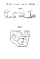
- FIG. 1 is a representational side elevational view of a portion of a data disk storage system showing the interrelationship between the stepper motor and the read/write heads that are moved across a data disk of the storage system.
- FIG. 2 is a top elevational view of a portion of a drive mechanism for controlling the movement of the read/write head between various tracks on the data disk.
- FIG. 3 is a representational view of a bipolar stepper motor such as would be used in accordance with the present invention.
- FIGS. 4a-4e are wave diagrams showing the torque applied to a rotor during half stepping operations as conventional in the art and quarter stepping operations in accordance with the present invention.
- FIGS. 5a, 5b and 5c are pulse diagrams indicating the magnitude of the torque generated on the rotor during the stepping operation during conventional full step and half step operations and quarter step operations in accordance with the present invention.
- FIGS. 6a, 6b and 6c illustrate the currents applied to phase coil A and phase coil B of the bipolar stepper motor during conventional full step and half step operations and a quarter step operation in accordance with the present invention.
- FIG. 7 is a schematic circuit diagram of a circuit utilized in carrying out the quarter step operation in accordance with the present invention.
- FIGS. 8a and 8b are voltage signal diagrams generated in a system utilizing a voltage feedback when the stepper motor is operated in a quarter step operation in accordance with the present invention and a conventional half step operation, respectively.
- FIG. 9 is a schematic circuit diagram of another embodiment of a control circuit utilized for carrying out the quarter step operation in accordance with the present invention.
- FIG. 10 is a schematic circuit diagram showing the portion of the control circuit for use in controlling the settling operation of the control arm during the stepping movement of such arm in accordance with the present invention.
- FIG. 11 is a wave diagram showing the varying voltage input signal resulting from detecting the velocity of the oscillation of the control arm as it settles to its rest position.
- FIG. 12 is a wave diagram of the digital output signal from the comparator receiving the signal shown in FIG. 11 and utilized for controlling the settling operation of the control arm in accordance with the present invention.
- FIG. 13 is a flow chart of the program for controlling a microprocessor in carrying out the quarter step operation in accordance with the present invention.
- FIG. 14 is a flow chart of the program for controlling a microprocessor in carrying out the settling operation for the control arm in accordance with the present invention.
- FIG. 1 A data disk storage system in which the bipolar stepper motor control system of the present invention is used is shown in FIG. 1.
- the particular data disk system shown is a Winchester disk drive system 2 in which the disks such as disks 6 and 8 are mounted on a hub 4. Hub 4 in turn is mounted on a rotational drive member 12 coupled to and driven by a motor within base 10.
- a bipolar stepper motor 16 which receives input signals from a series of wires 15 has an output shaft 18 which is coupled for moving the read/write heads such as magnetic head 14 across the data tracks on the data disks.
- Output shaft 18 is driven by the rotor of bipolar stepper motor 16 and this shaft rotates in incremental steps. As the motor output shaft rotates it imparts a linear motion to metal linking band 24, shown in FIG. 2, which is wrapped around shaft 18. Movement of the metal linking band in turn causes control drive arm 20 to be rotated about the axis of drive shaft 22. Movement of control drive arm 20 causes rotation of drive shaft 22 which in turn imparts a pivotal movement to arm 26 of the read/write head about the axis of drive shaft 22. Thus, arm 26 pivots about the axis of the drive shaft 22 thereby moving magnetic head 14 in and out along various tracks on data disk 6, which are shown in FIG. 2.
- the bipolar stepper motor 16 includes a permanent magnet rotor 28 which is driven by the torque created by the magnetic fields generated by stator phase A winding 30 and stator phase B winding 32, shown in FIG. 3.
- FIG. 4a the application of the torque to permanent magnet 28 by stator windings 30 and 32 can be understood.
- the four curves in FIG. 4a represent the torque generated when positive and negative oscillating currents are applied to windings 30 and 32.
- the four curves are torque curves for phase +A, phase -A, phase +B and phase -B.
- a stable stationary rotary position is created.
- These points are shown by arrows in FIG. 4a.
- These stable positions as shown in this figure are those positions created when current is applied to only one of these stator phases windings of the motor.
- all of the arrows are equally spaced and accordingly each of the stationary step positions are equally separated from each other.
- the rotor 28 of motor 16 is moved a full step when phase A and phase B are both simultaneously on with each combination of sign.
- a motor is moved a half step when each of the full stepped positions is separated by a position in which the current is removed from one of the windings. Consequently, 8 stable steps are produced in the operation of a half step motor which stable steps occur at the following conditions:
- positions 2, 4, 6 and 8 are full step detent positions and positions 1, 3, 5 and 7 are half step detent positions.
- both motor windings phase A and B shown in FIG. 3
- the individual step positions are defined by the direction of current flow in the two windings, which current directions are shown in FIG. 6a.
- These step positions are essentially balance points where the torque generated by the 2-phase currents cancel out.
- the motor takes up a "full step" position when BOTH phases (A and B) are energized (see FIG. 6a).
- FIG. 4a which shows the torque/angle characteristic for each phase of a 2-phase motor
- the positions 1 and 3 depict the step positions adopted when phase A or phase B respectively is energized (see FIG. 6b).
- These two step position are conventionally referred to as "half steps”; the slope of the torque curve at positions 1 and 3 (X and Y), see FIG. 4c, determine the stiffness at such step positions.
- the negative slope zero crossings represent imaginary step positions which are unstable.
- the 8 stable step positions occurring during one motor cycle with a half step operation are shown in FIG. 5b with the variance in the magnitude of arrow representing the difference in holding torque at each step position.
- FIG. 4b shows the resultant torque/angle characteristic C for a full step which is generated by summing the individual A and B phase characteristics. From FIG. 4b, it can be seen that the full step stable position Z lies exactly in between the two half step positions X and Y. In addition, the full step holding torque at position T is significantly greater than the half step holding torque. This increase in holding torque results in an increase in stiffness at step location Z. Hence, entirely different behavior characteristics occur in the half and full step positions.
- the bipolar stepper motor control system of the present invention provides a way of enhancing the performance of the stepper motor by maintaining the basic half step resolution while avoiding the disadvantages associated with conventional half stepping.
- FIG. 4c illustrates this position S.
- FIG. 4d shows how quarter step position S is generated.
- the resultant holding torque curve is curve C' which is formed by the summation of curve A and curve B'. Notice that the equilibrium point S lies one quarter of the distance between half step positions X and Y.
- phase B which is used for generating the stable quarter step position S can be applied to phase A for a given stepper motor. Consequently, if the currents in phases A and B are interchanged (i.e. A is now the low current winding) then a new quarter step position is defined.
- This new stable quarter step position R is shown in FIG. 4e. The new step position R lies three quarters of the way between the original half step positions X and Y.
- FIG. 5c which address every quarter step location in one full motor cycle.
- FIG. 5c the resulting holding torque in each of the quarter step positions is the same.
- FIG. 6c shows the magnitudes and directions of the phase currents required to cause the stepper motor shaft to take up the 8 quarter step positions.
- Step positions are defined that are separated by one half step.
- the circuit diagram shown in FIG. 7 contains a 2-phase stepper motor driven in the quarter step mode in accordance with the present invention by voltage programmable constant current sources.
- the operation of the phase A winding is described below (the operation of the phase B winding is identical).
- the constant current source 34 for phase A has two input lines (a) direction input 36, which is a digital input, and (b) program input 38, which is an analog input signal.
- direction input 36 which is a digital input
- program input 38 which is an analog input signal.
- logic "1" specifies that the current will flow through the motor winding from D to E in phase winding A; logic "0" specifies the reverse direction.
- the analog program input defines the current level that is maintained in the stepper motor; 0 volts specifies zero current and +5 volts specifies normal (high) motor current.
- the direction input is driven from a microprocessor or suitable hardwired logic.
- the program input is driven by a times 1 inverting operational amplifier A1.
- the voltage seen by the input of amplifier A1 through resistor R3 at the junction of resistors R4 and R5 is either OV when the transistor Q1 is ON or (R5/(R4+R5)) *5 V when transistor Q1 is OFF.
- This latter voltage when inverted with respect to the REF voltage (2.5 V) by the operational amplifier defines a low voltage of approximately 1 V at the program input 38 to the current source.
- current source 34 In response to this low voltage at input 38, current source 34 generates a low current in the motor phase A winding.
- When Q1 is ON, the output of amplifier A1 is +5 V and the current source turns on normal (high) current.
- the output from amplifier A1 in the quarter step operation is shown in FIG. 8a, as further described below.
- a control circuit for producing two distinct, defined currents in each motor phase winding; the high current being set by the current source itself and the low current being defined by the ratio R4/R5 from the resistors R4 and R5 that form a voltage divider.
- the quarter step method of stepper drive operation in the disk drive system is particularly advantageous in systems employing a velocity feedback signal to control the settling performance of the stepper motor.
- an error signal derived from a tachometer is summed together with the command signal to produce an actuating current signal to be supplied to the motor phase winding.
- error signals from a tacho/amplifier can be summed into the circuit at points 42 and 44.
- the form of the output from the operational amplifiers A1 and A2 is then essentially a digital signal with an analog voltage superimposed as shown in FIG. 8a. Since the current demand signal at the output of the operational amplifiers is always at least 1 V in the quarter step method of operation, the analog error signal can be added to such amplifier output signal for input into constant current source 34 and still remain within the linear range of operation of the constant current source 34. This linearity is maintained provided that the velocity error signal is less than +/- 1 V and assuming that the current sources continue to behave linearly for inputs greater than 5 V.
- the quarter step mode of operation of a stepper motor with velocity feedback as described above has been implemented in a 5.25 inch computer peripheral disk drive system.
- the stepper motor is used for positioning the read/write heads over the desired data track on the data disk.
- the density of the data tracks that can be achieved is primarily a function of the resolution and accuracy of the stepper motor.
- the access time of the disk drive is determined by the maximum speed and acceleration of the stepper motor and by the settling time at the end of the seek operation in which the read/write head is moved to the selected data track. Consequently, the stepper motor has a direct bearing on the two most important parameters of the operation of the disk drive system, i.e. capacity of the system and access time to data on the disk.
- the accuracy of the stepper motor is maximized by making the stiffness of the stepper motor the same for all step positions and the settling time of the read/write head is minimized by using velocity feedback on the final motor step.
- FIG. 9 shows a block diagram for the control circuit utilized in the disk drive system in accordance with the present invention.
- Current sources 52 and 54 supply current to phase windings A and B of the stator of stepper motor 50.
- Amplifiers A1 and A2 along with the associated resistors and the open collector gates G1 and G2 form the basic quarter step/velocity feedback control circuit for driving the stepper motor.
- Resistors R4 and R5 provide the voltage divider used in varying the current for generating the quarter step positions as discussed above.
- Input control signals P, Q, R and S provide the signals for varying the direction and magnitude of the current supplied to phase windings A and B of motor 50, as discussed above in conjunction with the circuit diagram of FIG. 7.
- the output from tachometer 40 is amplified and inverted by amplifier A3 and fed to the analog switches S1 and S3.
- This signal from amplifier A3 also is fed to and inverted by amplifier A4 and the output from this amplifier is supplied to the analog switches S2 and S4.
- resistor R6 determines the gain of the feedback loop. This velocity feedback system is only effective within one step; the control circuit does not provide a velocity feedback signal while the motor is stepping.
- Control signals P, Q, R, S, T, V, W and X are generated by an Intel 8749 microprocessor.
- the basic flow chart for the program in this microprocessor are show in FIG. 13.
- This microprocessor controls the sequencing of the phase and direction lines during stepping and the selection of velocity error signals during settling time.
- P, Q, R and S (see Table II) define each step position and T, V, W and X (see Table III) are held low to turn all the feedback selector switches off.
- the last step is reached, simultaneously with the last phase change on P, Q, R and S, the appropriate velocity feedback signal is selected for each motor phase via T, V, W and X.
- the correct feedback signal for each phase is determined from the direction of current flow in that phase and by the direction of motion of the motor.
- the maximum dynamic range used by the velocity error signal is +/- 0.6 V peak to peak at the inputs to the current sources.
- the resistors R4 and R5 can be selected such that the track separation is optimum and symmetrical over a motor cycle of eight steps. If the worst case of separation between the desired final resting location and actual location is defined as being the closest approach of two adjacent steps from any direction, then experiments show that this worst separation can be increased from typically 80% of nominal when half stepping to greater than 88% when quarter stepping, i.e. only a 12% distortion error with quarter stepping as compared to 20% when half stepping.
- the system behaves as a classical second order system within the confines of one step. This means that critical damping can be achieved with considerable reductions in seek times for single and multiple track seeks.
- a one track seek one motor step
- using quarter stepping has reduced the total seek time (including settling) from typically 10 ms in the half step mode to 5 ms. This improvement is derived purely from the elimination of non-linear effects present in the half step condition when the feedback signal approaches OV.
- Table IV shows the feedback selector signals output by the microprocessor for a full motor cycle. (Note that these states are only set up if the motor is required to stop on the step in question.)
- This velocity error signal generated by the control microprocessor can be used to determine when the control arm with the coupled read/write head is at rest after the settling time is complete.
- a window comparator 60 is used to ascertain when the velocity error signal is within defined limits. The output of this comparator is fed to the processor (MP) where the excursions of the velocity signal outside the window are analyzed.
- FIG. 14 A flow chart of the program in the microprocessor is shown in FIG. 14. The analysis consists of initializing a software timer in the processor when the velocity error signal first enters the defined window (point A on the wave in FIG. 11). The period of this timer is set to be just greater than half the natural period of the actuating assembly. If the velocity signal subsequently leaves the window (point B on the wave in FIG. 11), then the timer is stopped and reinitialized again when the velocity signal re-enters the window (point C on the wave in FIG. 11).
Landscapes
- Engineering & Computer Science (AREA)
- Power Engineering (AREA)
- Control Of Stepping Motors (AREA)
Abstract
Description
______________________________________
Step Positions
             Bit 3  Bit 2      Bit 1
                                    Bit 0
______________________________________
0            1      0          1    1
1            0      0          1    1
2            0      1          1    0
3            0      1          0    0
4            0      0          0    1
5            1      0          0    1
6            1      1          0    0
7            1      1          1    0
______________________________________
______________________________________
Step          Phase A  Phase B
______________________________________
1             +        0
2             +        +
3             0        +
4             -        +
5             -        0
6             -        -
7             0        -
8             +        -
______________________________________
              TABLE I
______________________________________
Step   A-DI-     A-MAG-     B-DI-   B-MAG-
Number RECTION   NITUDE     RECTION NITUDE
______________________________________
1      1         0          1       1
2      0         0          1       1
3      0         1          1       0
4      0         1          0       0
5      0         0          0       1
6      1         0          0       1
7      1         1          0       0
8      1         1          1       0
______________________________________
              TABLE II
______________________________________
Quarter Step Magnitude and Direction Information Table
ADDRESS          DATA
Phase Table Base Address
                 Bit 3  Bit 2    Bit 1
                                      Bit 0
______________________________________
+0               1      0        1    1
+1               0      0        1    1
+2               0      1        1    0
+3               0      1        0    0
+4               0      0        0    1
+5               1      0        0    1
+6               1      1        0    0
+7               1      1        1    0
______________________________________
Data Bit 0 is Phase B Magnitude [S]
                    (0 = high current)
                    (1 = low current)
Data Bit 1 is Phase B Current Direction [Q]
Data Bit 2 is Phase A Magnitude [R]
                    (0 = high current)
                    (1 = low current)
Data Bit 3 is Phase A Current Direction [P]
(Accessed by Modulo - 8 Counter) (This pattern is repeated every
8 motor steps.)
______________________________________
              TABLE III
______________________________________
Damping Selector Table
ADDRESS          DATA
Damping Table Base Address
                 Bit 3  Bit 2    Bit 1
                                      Bit 0
______________________________________
+0               0      1        1    0
+1               1      0        0    1
+2               1      0        0    1
+3               0      1        1    0
+4               0      1        1    0
+5               1      0        0    1
+6               1      0        0    1
+7               0      1        1    0
______________________________________
Data Bit 0 Links the Velocity Signal to Channel B [W]
Data Bit 1 Links the Velocity Signal to Channel B [X]
Data Bit 2 Links the Velocity Signal to Channel A [T]
Data Bit 3 Links the Velocity Signal to Channel A [V]
(Accessed by Modulo - 8 Step Counter). (This pattern is repeated every
8 motor steps.)
______________________________________
              TABLE IV
______________________________________
Step     +A      -A          +B    -B
Num-     FEED    FEED        FEED  FEED
ber      BACK    BACK        BACK  BACK
______________________________________
1        0       1           1     0
2        1       0           0     1
3        1       0           0     1
4        0       1           1     0
5        0       1           1     0
6        1       0           0     1
7        1       0           0     1
8        0       1           1     0
______________________________________
Claims (26)
______________________________________
Step Positions
             Bit 3  Bit 2      Bit 1
                                    Bit 0
______________________________________
0            1      0          1    1
1            0      0          1    1
2            0      1          1    0
3            0      1          0    0
4            0      0          0    1
5            1      0          0    1
6            1      1          0    0
7            1      1          1    0
______________________________________
______________________________________
Step Positions
             Bit 3  Bit 2      Bit 1
                                    Bit 0
______________________________________
0            1      0          1    1
1            0      0          1    1
2            0      1          1    0
3            0      1          0    0
4            0      0          0    1
5            1      0          0    1
6            1      1          0    0
7            1      1          1    0
______________________________________
Priority Applications (1)
| Application Number | Priority Date | Filing Date | Title |
|---|---|---|---|
| US06/573,708 US4518904A (en) | 1984-01-25 | 1984-01-25 | Stepper motor control for data disk system |
Applications Claiming Priority (1)
| Application Number | Priority Date | Filing Date | Title |
|---|---|---|---|
| US06/573,708 US4518904A (en) | 1984-01-25 | 1984-01-25 | Stepper motor control for data disk system |
Publications (1)
| Publication Number | Publication Date |
|---|---|
| US4518904A true US4518904A (en) | 1985-05-21 |
Family
ID=24293081
Family Applications (1)
| Application Number | Title | Priority Date | Filing Date |
|---|---|---|---|
| US06/573,708 Expired - Fee Related US4518904A (en) | 1984-01-25 | 1984-01-25 | Stepper motor control for data disk system |
Country Status (1)
| Country | Link |
|---|---|
| US (1) | US4518904A (en) |
Cited By (23)
| Publication number | Priority date | Publication date | Assignee | Title |
|---|---|---|---|---|
| US4703244A (en) * | 1985-05-02 | 1987-10-27 | Tokyo Keiki Company Ltd. | Pulse motor control apparatus |
| DE3723280A1 (en) * | 1986-07-16 | 1988-01-21 | Fuji Electric Co Ltd | HEAD POSITION CONTROL SYSTEM FOR A DISK STORAGE UNIT |
| US4727304A (en) * | 1986-11-10 | 1988-02-23 | Ibm Corporation | Phase sequencer for stepping motor |
| EP0229891A3 (en) * | 1985-10-22 | 1988-08-17 | Nec Corporation | Head positioning system for floppy disk drives |
| US4789909A (en) * | 1985-09-12 | 1988-12-06 | Fuji Electric Company Ltd. | Method and apparatus for placing servo information at predetermined locations on a disc |
| US4982146A (en) * | 1988-07-19 | 1991-01-01 | Fuji Electric Co., Ltd. | Stepping motor driving device |
| EP0378330A3 (en) * | 1989-01-10 | 1991-08-14 | Fujitsu Limited | Servo circuit control system |
| US5189576A (en) * | 1990-12-19 | 1993-02-23 | Integral Peripherals, Inc. | Rotary inertial latch for disk drive actuator |
| US5218253A (en) * | 1990-12-19 | 1993-06-08 | Integral Peripherals, Inc. | Spin motor for a hard disk assembly |
| US5258695A (en) * | 1990-12-19 | 1993-11-02 | Integral Peripherals, Inc. | Spin motor control system for a hard disk assembly |
| US5296986A (en) * | 1990-12-19 | 1994-03-22 | Integral Peripherals, Inc. | Rotary intertial latch for disk drive actuator to protect against rotational shock force |
| US5377065A (en) * | 1990-12-19 | 1994-12-27 | Integral Peripherals, Inc. | Miniature hard disk drive for portable computer having a rotary inertial latch for disk drive actuator |
| US5379171A (en) * | 1991-09-25 | 1995-01-03 | Integral Peripherals | Microminiature hard disk drive |
| US5404257A (en) * | 1990-12-19 | 1995-04-04 | Integral Peripherals, Inc. | Rotary inertial latch for disk drive actuator |
| US5596458A (en) * | 1994-12-19 | 1997-01-21 | Integral Peripherals, Inc. | Variable zone layout for information storage disk drive |
| US5847535A (en) * | 1996-01-31 | 1998-12-08 | Parker-Hannifin Corporation | Active electronic damping for step motor |
| US5995330A (en) * | 1990-12-19 | 1999-11-30 | Mobile Storage Technology Inc. | Rigid disk drive with dynamic head loading apparatus |
| US6005725A (en) * | 1994-12-19 | 1999-12-21 | Mobile Storage Technology Inc. | Variable zone layout and track pitch parameter considerations for information storage disk drive |
| US6310747B1 (en) | 1991-09-25 | 2001-10-30 | Mobile Storage Technology, Inc. | Method for reducing external signal interference with signals in a computer disk storage system |
| US20050174910A1 (en) * | 2004-02-10 | 2005-08-11 | Samsung Electronics Co., Ltd | Method for controlling stepping motor |
| US7342741B1 (en) | 2000-02-10 | 2008-03-11 | Esgw Holdings Limited | Disk drive with variable track density |
| US20120056574A1 (en) * | 2007-09-10 | 2012-03-08 | Panasonic Corporation | Stepping motor driver |
| WO2025078238A1 (en) * | 2023-10-12 | 2025-04-17 | Thomas Magnete Gmbh | Control device for a stepper motor |
Citations (1)
| Publication number | Priority date | Publication date | Assignee | Title |
|---|---|---|---|---|
| US4215302A (en) * | 1978-01-26 | 1980-07-29 | Mcc Associates | Control system for stepping motors, a method of operating stepping motors, and a method for selecting current patterns for stepping motors |
-
1984
- 1984-01-25 US US06/573,708 patent/US4518904A/en not_active Expired - Fee Related
Patent Citations (1)
| Publication number | Priority date | Publication date | Assignee | Title |
|---|---|---|---|---|
| US4215302A (en) * | 1978-01-26 | 1980-07-29 | Mcc Associates | Control system for stepping motors, a method of operating stepping motors, and a method for selecting current patterns for stepping motors |
Cited By (46)
| Publication number | Priority date | Publication date | Assignee | Title |
|---|---|---|---|---|
| US4703244A (en) * | 1985-05-02 | 1987-10-27 | Tokyo Keiki Company Ltd. | Pulse motor control apparatus |
| US4789909A (en) * | 1985-09-12 | 1988-12-06 | Fuji Electric Company Ltd. | Method and apparatus for placing servo information at predetermined locations on a disc |
| EP0229891A3 (en) * | 1985-10-22 | 1988-08-17 | Nec Corporation | Head positioning system for floppy disk drives |
| DE3723280A1 (en) * | 1986-07-16 | 1988-01-21 | Fuji Electric Co Ltd | HEAD POSITION CONTROL SYSTEM FOR A DISK STORAGE UNIT |
| US4777417A (en) * | 1986-07-16 | 1988-10-11 | Fuji Electric Company, Ltd. | Head position control system for a disc storage unit |
| US4727304A (en) * | 1986-11-10 | 1988-02-23 | Ibm Corporation | Phase sequencer for stepping motor |
| US4982146A (en) * | 1988-07-19 | 1991-01-01 | Fuji Electric Co., Ltd. | Stepping motor driving device |
| EP0378330A3 (en) * | 1989-01-10 | 1991-08-14 | Fujitsu Limited | Servo circuit control system |
| US5995330A (en) * | 1990-12-19 | 1999-11-30 | Mobile Storage Technology Inc. | Rigid disk drive with dynamic head loading apparatus |
| US6057987A (en) * | 1990-12-19 | 2000-05-02 | Mobile Storage Technology Inc. | Rigid disk drive with dynamic head loading apparatus and method of manufacturing a rigid disk drive with dynamic head loading apparatus |
| US5258695A (en) * | 1990-12-19 | 1993-11-02 | Integral Peripherals, Inc. | Spin motor control system for a hard disk assembly |
| US5296986A (en) * | 1990-12-19 | 1994-03-22 | Integral Peripherals, Inc. | Rotary intertial latch for disk drive actuator to protect against rotational shock force |
| US5377065A (en) * | 1990-12-19 | 1994-12-27 | Integral Peripherals, Inc. | Miniature hard disk drive for portable computer having a rotary inertial latch for disk drive actuator |
| US5218253A (en) * | 1990-12-19 | 1993-06-08 | Integral Peripherals, Inc. | Spin motor for a hard disk assembly |
| US5404257A (en) * | 1990-12-19 | 1995-04-04 | Integral Peripherals, Inc. | Rotary inertial latch for disk drive actuator |
| US5408374A (en) * | 1990-12-19 | 1995-04-18 | Integral Peripherals, Inc. | Miniature hard disk drive with spin motor for portable computer |
| US5426562A (en) * | 1990-12-19 | 1995-06-20 | Integral Peripherals | Disk drive enclosed by shock absorbent jacket and mounted in electronic instrument |
| US5442266A (en) * | 1990-12-19 | 1995-08-15 | Integral Peripherals, Inc. | Miniature disk drive with spin motor control system |
| US5448433A (en) * | 1990-12-19 | 1995-09-05 | Integral Peripherals | Disk drive information storage device with baseplate and cover having overlapping edge portions to provide protection from electromagnetic interference |
| US5466997A (en) * | 1990-12-19 | 1995-11-14 | Integral Peripherals, Inc. | Spin motor control system for a hard disk assembly |
| US5469314A (en) * | 1990-12-19 | 1995-11-21 | Integral Peripherals, Inc. | Miniature disk drive with dynamic head loading |
| US5486964A (en) * | 1990-12-19 | 1996-01-23 | Integral Peripherals, Inc. | Miniature disk drive with dynamic head loading with skewed lifting tab |
| US6032352A (en) * | 1990-12-19 | 2000-03-07 | Mobile Storage Technology Inc. | Method of manufacturing rigid disk drive with dynamic head loading apparatus |
| US5189576A (en) * | 1990-12-19 | 1993-02-23 | Integral Peripherals, Inc. | Rotary inertial latch for disk drive actuator |
| US5689386A (en) * | 1990-12-19 | 1997-11-18 | Integral Peripherals, Inc. | Miniature hard disk drive with EMI protection and single permanent magnet rotary actuator having an improved housing seal |
| US5579189A (en) * | 1991-09-25 | 1996-11-26 | Integral Peripherals, Inc. | Microminiature hard disk drive |
| US5592349A (en) * | 1991-09-25 | 1997-01-07 | Integral Peripherals, Inc. | Microminiature disk drive with clamp having fingers for radially positioning a pair of disks and a spindle motor providing a reduced disk drive height |
| US5760986A (en) * | 1991-09-25 | 1998-06-02 | Integral Peripherals, Inc. | Microminiature hard disk drive |
| US5835303A (en) * | 1991-09-25 | 1998-11-10 | Integral Peripherals, Inc. | Microminiature hard disk drive |
| US6310747B1 (en) | 1991-09-25 | 2001-10-30 | Mobile Storage Technology, Inc. | Method for reducing external signal interference with signals in a computer disk storage system |
| US5867340A (en) * | 1991-09-25 | 1999-02-02 | Mobile Storage Technology Inc. | Microminiature hard disk drive with adaptive runout compensation |
| US5379171A (en) * | 1991-09-25 | 1995-01-03 | Integral Peripherals | Microminiature hard disk drive |
| US5694267A (en) * | 1991-09-25 | 1997-12-02 | Integral Peripherals, Inc. | Removable disk drive and protective device |
| US5870237A (en) * | 1994-12-19 | 1999-02-09 | Integral Peripherals, Inc. | Method for variable zone layout for information storage disk drive |
| US6005725A (en) * | 1994-12-19 | 1999-12-21 | Mobile Storage Technology Inc. | Variable zone layout and track pitch parameter considerations for information storage disk drive |
| US5946153A (en) * | 1994-12-19 | 1999-08-31 | Mobile Storage Technology Inc. | Information storage disk drive with variable zone layout |
| US6091559A (en) * | 1994-12-19 | 2000-07-18 | Mobile Storage Technology Inc. | Variable zone layout and track pitch parameter considerations for information storage disk drive |
| US5596458A (en) * | 1994-12-19 | 1997-01-21 | Integral Peripherals, Inc. | Variable zone layout for information storage disk drive |
| US6260257B1 (en) | 1994-12-19 | 2001-07-17 | Mobile Storage Technology, Inc. | Method of manufacturing an information storage disk drive with variable zone layout and track pitch parameter considerations |
| US5847535A (en) * | 1996-01-31 | 1998-12-08 | Parker-Hannifin Corporation | Active electronic damping for step motor |
| US7342741B1 (en) | 2000-02-10 | 2008-03-11 | Esgw Holdings Limited | Disk drive with variable track density |
| US20050174910A1 (en) * | 2004-02-10 | 2005-08-11 | Samsung Electronics Co., Ltd | Method for controlling stepping motor |
| US7701162B2 (en) * | 2004-02-10 | 2010-04-20 | Samsung Electronics Co., Ltd. | Method for controlling stepping motor |
| US20120056574A1 (en) * | 2007-09-10 | 2012-03-08 | Panasonic Corporation | Stepping motor driver |
| US8362734B2 (en) * | 2007-09-10 | 2013-01-29 | Panasonic Corporation | Stepping motor driver |
| WO2025078238A1 (en) * | 2023-10-12 | 2025-04-17 | Thomas Magnete Gmbh | Control device for a stepper motor |
Similar Documents
| Publication | Publication Date | Title |
|---|---|---|
| US4518904A (en) | Stepper motor control for data disk system | |
| US4658194A (en) | Closed loop control circuitry for step motors | |
| JP3540123B2 (en) | Control device and control method for stepping motor | |
| US5808440A (en) | Hybrid communication method and apparatus for a three-phase brushless DC motor | |
| US5227709A (en) | Closed loop single step response by open winding voltage feedback system and method for multiple phase step motors | |
| US6498446B1 (en) | System and method for optimizing torque in a polyphase disk drive motor | |
| US5886489A (en) | Apparatus and method for reducing spindle power and acoustic noise in a disk drive | |
| KR910007909B1 (en) | Head - positioner for disk apparatus | |
| US6801382B2 (en) | Magnetic disk storage apparatus | |
| US5825151A (en) | Apparatus for driving stepping motor | |
| US6122234A (en) | Recording disk drive using a synchronous driving motor | |
| EP1136998A1 (en) | Fully digital control and drive combo IC with on-board DSP for disk mass storage device | |
| KR20040004831A (en) | Method for controlling a step motor of optical disc driving system and apparatus therefor | |
| JP2740643B2 (en) | Stepping motor drive | |
| JPH0646598A (en) | Vernier-controlled stepper electric motor and its control method | |
| US6072656A (en) | Stepping motor control method | |
| JPH09219995A (en) | Drive method of stepping motor | |
| JP3325485B2 (en) | Stepping motor control method and disk device | |
| JPH09313000A (en) | Method of driving stepping motor | |
| JP2559774B2 (en) | Disk drive system | |
| US5581421A (en) | Method for driving stepping motor for head seek in disk drive device | |
| JP2636288B2 (en) | Disk device positioning device | |
| JP2639004B2 (en) | Disk device positioning device | |
| JPH06303799A (en) | Method of driving stepping motor | |
| JP2770729B2 (en) | Head access control method |
Legal Events
| Date | Code | Title | Description |
|---|---|---|---|
| AS | Assignment |
Owner name: RODIME PLC, ROTHESAY HOUSE, ROTHESAY PLACE, GLENRO Free format text: ASSIGNMENT OF ASSIGNORS INTEREST.;ASSIGNORS:MACLEOD, NIGEL;RUXTON, DAVID;REEL/FRAME:004221/0616 Effective date: 19840113 |
|
| CC | Certificate of correction | ||
| FPAY | Fee payment |
Year of fee payment: 4 |
|
| AS | Assignment |
Owner name: BANK OF SCOTLAND Free format text: SECURITY INTEREST;ASSIGNOR:RODIME PLC;REEL/FRAME:005808/0907 Effective date: 19900928 |
|
| FEPP | Fee payment procedure |
Free format text: PAYOR NUMBER ASSIGNED (ORIGINAL EVENT CODE: ASPN); ENTITY STATUS OF PATENT OWNER: LARGE ENTITY |
|
| FPAY | Fee payment |
Year of fee payment: 8 |
|
| REMI | Maintenance fee reminder mailed | ||
| LAPS | Lapse for failure to pay maintenance fees | ||
| FP | Lapsed due to failure to pay maintenance fee |
Effective date: 19970521 |
|
| STCH | Information on status: patent discontinuation |
Free format text: PATENT EXPIRED DUE TO NONPAYMENT OF MAINTENANCE FEES UNDER 37 CFR 1.362 |