US4516339A - Combination excavating bucket, shank and digging teeth - Google Patents
Combination excavating bucket, shank and digging teeth Download PDFInfo
- Publication number
- US4516339A US4516339A US06/572,592 US57259284A US4516339A US 4516339 A US4516339 A US 4516339A US 57259284 A US57259284 A US 57259284A US 4516339 A US4516339 A US 4516339A
- Authority
- US
- United States
- Prior art keywords
- tooth
- teeth
- bucket
- faces
- Prior art date
- Legal status (The legal status is an assumption and is not a legal conclusion. Google has not performed a legal analysis and makes no representation as to the accuracy of the status listed.)
- Expired - Lifetime
Links
- 230000000295 complement effect Effects 0.000 description 5
- 229910000831 Steel Inorganic materials 0.000 description 3
- 230000015572 biosynthetic process Effects 0.000 description 3
- 239000000463 material Substances 0.000 description 3
- 239000002184 metal Substances 0.000 description 3
- 239000010959 steel Substances 0.000 description 3
- 229910000851 Alloy steel Inorganic materials 0.000 description 2
- 229910045601 alloy Inorganic materials 0.000 description 2
- 239000000956 alloy Substances 0.000 description 2
- 229910003460 diamond Inorganic materials 0.000 description 2
- 239000010432 diamond Substances 0.000 description 2
- 230000009977 dual effect Effects 0.000 description 2
- 238000004519 manufacturing process Methods 0.000 description 1
- 238000000034 method Methods 0.000 description 1
- 239000007787 solid Substances 0.000 description 1
- 230000036346 tooth eruption Effects 0.000 description 1
Images


Classifications
-
- E—FIXED CONSTRUCTIONS
- E02—HYDRAULIC ENGINEERING; FOUNDATIONS; SOIL SHIFTING
- E02F—DREDGING; SOIL-SHIFTING
- E02F9/00—Component parts of dredgers or soil-shifting machines, not restricted to one of the kinds covered by groups E02F3/00 - E02F7/00
- E02F9/28—Small metalwork for digging elements, e.g. teeth scraper bits
- E02F9/2808—Teeth
Definitions
- the backhoe-type digging machine excavates material from the earth in an efficient and rapid manner.
- the backhoe machines are available in various different sizes and sometimes cost more than a quarter million dollars.
- the hourly cost of operating the large backhoe bucket is astronomical; but on the other hand, the cost is very little compared with the results, and especially the results when contrasted with other methods of excavating earth.
- the backhoe bucket design directly governs the efficiency of operation of the entire backhoe machine.
- the design of the digging teeth is directly related to the overall efficiency of a particular bucket.
- the condition of the digging teeth can influence the digging efficiency more than 50 percent, depending upon the type of formation being excavated. In some instances, as the digging teeth progressively wear, the efficiency can drop from 300 feet of ditch per day, down to less than 100 feet of ditch per day. Accordingly, it is desirable that the backhoe bucket be provided with a bucket of efficient design, having sharp digging teeth thereon which likewise are of optimum design respective to the bucket and to the formation being excavated.
- This invention comprehends a combination backhoe bucket, tooth-receiving shanks, and digging teeth therefor.
- the invention further comprehends a combination shank and digging tooth therefor.
- the tooth-receiving shank of the present invention comprises an elongated main body having a forward and rear portion aligned respective to a bucket so that a tooth mounted within a tooth-receiving pocket thereof is disposed forwardly of the bucket in aligned relationship respective to the direction of travel of the bucket.
- the tooth has a main body which is a polygon in cross-section.
- the polygon preferably is a quadrilateral, and more specifically is square in cross-sectional area.
- the opposed ends of the teeth are provided with identical cutting edges by the formation of parallel oblique faces arranged parallel to one another and defining the extremities of the tooth.
- the oblique face preferably is a plane in the form of a diamond, with each corner of the diamond being one corner of the quadrilateral or square.
- the configuration of the pocket is complementary to the configuration of either marginal end of a tooth so that the cutting face, cutting edge, and side walls of the tooth are received in close tolerance relationship with complementary arranged wall surfaces of the pocket.
- a pocket and tooth enables the digging teeth to be reversed within a pocket of a shank, thereby providing each of the teeth with dual cutting edges, and enabling any one of the teeth to be interchanged for another, as well as being reversed as may be required as the cutting edge is worn.
- This remarkable configuration of a digging tooth further enables the cutting edges thereof to be resurfaced or dressed in the field so that the digging bucket is essentially provided with an inexhaustible supply of sharp digging teeth.
- the teeth of this invention are fabricated from an elongated piece of metal stock of satisfactory alloy, which has been normalized and sawed at spaced intervals, with each of the saw lines being arranged parallel to one another and defining the face of the teeth.
- the teeth are subsequently heat treated to achieve optimum hardness.
- a primary object of the present invention is the provision of a backhoe bucket, shank, and tooth combination which enables any one tooth to be exchanged for any other tooth, as well as enabling each of the teeth to be reversed within a pocket in order to present a new cutting edge forwardly of the bucket.
- Another object of the invention is to provide a tooth and shank combination, wherein the tooth has cutting edges formed on opposed marginal ends of the cutting teeth, and with the shank having a pocket made complementary respective to either marginal end of the tooth.
- a further object of this invention is to disclose and provide a tooth and pocket combination in which the digging tooth is provided with a cutting edge at each extremity thereof so that either cutting edge can be utilized by reversing the tooth within the pocket.
- a still further object of this invention is to provide a tooth and shank combination which enables digging loads encountered by the cutting edge of the tooth to be transferred into the shank and then into the bucket in an improved and unusual manner.
- Another and still further object is to provide a tooth and shank combination which enables the digging tooth to be reversed within a pocket of the shank to present a new cutting edge, and which furthermore enables the cutting edge of the tooth to be field dressed in an easy and efficient manner.
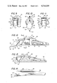
- FIG. 1 is a broken, side elevational view of a combination backhoe bucket, shank, and tooth made in accordance with the present invention.
- FIG. 2 is an enlarged, perspective view of the digging bucket seen in FIG. 1;
- FIG. 3 is a reduced, broken, top view of the apparatus disclosed in FIG. 2;
- FIG. 4 is a reduced, front view of the apparatus disclosed in FIG. 2;
- FIG. 5 is an enlarged, broken, top plan view of the apparatus disclosed in FIG. 4;
- FIGS. 6, 7, and 8, respectively, are top and side elevational views of the digging teeth disclosed in the foregoing figures;
- FIGS. 9, 10, and 11, respectively are front elevational views of the combination disclosed in FIGS. 6, 7, and 8, respectively;
- FIG. 12 is a side elevational view of the apparatus disclosed in FIG. 8;
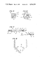
- FIG. 13 is a cross-sectional view of part of the apparatus disclosed in FIG. 12;
- FIG. 14 discloses the opposite side of part of the apparatus disclosed in FIG. 12;
- FIG. 15 is a cross-sectional view taken along line 15--15 of FIG. 12;
- FIG. 16 is a rear view of the apparatus disclosed in FIG. 12;
- FIG. 17 diagrammatically illustrates a flow sheet of the manufacture of part of the apparatus disclosed in the foregoing figures.
- FIG. 18 is a schematical, cross-sectional view of a ditch which has been dug using the apparatus disclosed in FIG. 1.
- FIG. 1 discloses a backhoe bucket 10, preferably made in accordance with my previous U.S. Pat. Nos. 4,037,337 and 4,123,861.
- the bucket includes a plurality of shanks and teeth, generally indicated by the numeral 12, positioned at the forward end of the bucket.
- the bucket is attached to the dipper stick 14 of a backhoe (not shown).
- the bucket includes a lip 16 having a front edge 18.
- a plurality of teeth-receiving shanks 20 each has a rear marginal edge portion affixed to the forward marginal edge portion of the lip.
- a tooth 22 has a rear marginal length which is received within a pocket formed within the forward marginal edge portion of each of the shanks. For purposes of illustration, some of the shanks in FIG. 2 have the teeth removed therefrom.
- the bucket lip is in the form of a "V", with one side of the V having a plurality of teeth and shanks 24 attached thereto, the other side of the V-shaped lip has a plurality of teeth and shanks 26 affixed thereto, with there being a central tooth and shank at 28 connected along the apex 30 of the V.
- the apex also forms the keel or central portion of the bucket.
- the keel extends longitudinally of the bucket, while the lip extends laterally of the bucket.
- the shanks at 24 are mirror images of the shanks at 26, and the shank at 28 is made more or less symmetrical. Therefore, the shanks at 24 and 26 are asymmetrical.
- One side 32 of the V-shaped bucket bottom is connected to the other side 34 of the V-shaped bottom, and the entire bottom is connected to opposed bucket side walls 36 and 38.
- FIGS. 6-11 illustrate the details of the teeth and shanks seen at 24, 26, and 28 in the previous figures of the drawings.
- the shank 24 has a main body 40 which terminates forwardly at shoulder 42.
- the rear marginal portion of the shank is in the form of a lower tang 44 having a rear marginal end spaced from upper tang 46, thereby leaving a lip-receiving opening or slot 48 between the upper and lower tangs.
- the shank has a trailing end 50 which is also the free terminal end of the lower shank.
- a lightening hole 52 is formed in the upper face of the lower tang to conserve material and weight.
- each of the shanks is provided with sloped walls 54 and 56 which are joined at apex 58.
- a pin hole 60 extends through the shank and engages a tooth which may be contained therewithin so that the tooth is removably mated within the pocket of the shank. The entrance into the pocket is defined by the shoulder 42.
- the foward tip 64 defines one terminal end of the tooth, while an identical tip 66 forms the opposite terminal end of the tooth.
- the tip 64 also defines the beginning of a face 68, and the face 68 forms the forward cutting edges of the tooth.
- the main body of the tooth includes side walls 74, 75, 76, 77, which terminate forwardly in the before mentioned edge portions and which terminate rearwardly in identical edge portions.
- the face 68 is parallel to the face 69.
- the pocket 62 includes a roof 78, a floor 79, side walls 80, and a rear wall 82.
- the tip 66 of the tooth is received at apex 84 of the rearwardly converging walls.
- the pocket 62 is made complementary respective to a marginal end of the tooth, with the side walls of the tooth being received in close tolerance relationship respective to the side walls of the pocket, and with the face of the tooth being received in abutting relationship respective to the rear wall 84 of the pocket, and with the tip 66 of the tooth being received within the similarly contoured or complementary shaped apex 84.
- FIG. 17 there is disclosed an elongated, longitudinally extending length of suitable alloy steel 95 which has been normalized so that the steel is relatively soft and can be easily cut.
- the long, rectangular body of steel has been milled at spaced locations 60' to provide a groove across one entire face of the tooth side wall.
- the groove 60' registers with the pin hole 60 so that a rolled pin or the like can be driven through the pin hole 60 and groove 60', thereby releasably affixing the tooth within the pocket of a shank.
- the metal stock 95 is sawed along parallel saw lines 85 to provide a plurality of teeth 22, 22', 22", with each of the teeth being identical, and with the saw line defining the opposed cutting faces 68, 69 of the teeth.
- the individual teeth are heat treated at 96, thereby providing a heat-treated tooth 22 of suitable alloy which has been brought to optimum hardness, and which can be used in conjunction with a shank and bucket in accordance with the present invention.
- FIG. 18 there is disclosed a ditch 86 which has been dug with the bucket of FIG. 2.
- the teeth 22 in FIG. 2 are arranged at 24 and form the ledges 88 of FIG. 18; and that the tooth 22 located at 28 in FIG. 2 has formed the bottommost ledge 90, while the teeth 22 located at 26 in FIG. 2 have dug ledges 92 of FIG. 18.
- the cutting face of the teeth at 24 is aligned such that the face slopes upwardly towards the top of the bucket and inwardly towards the central tooth 28.
- the teeth at 26 are located opposite to the teeth at 24 so that the face of the teeth 26 also slopes upwardly towards the top of the bucket and inwardly towards the central tooth 28. This arrangement of the cutting faces of the teeth causes excavated material to flow into the bucket in a superior manner.
- central tooth 28 is located inwardly of the other teeth 24 and 26, with adjacent teeth being located forwardly and above the tooth 28, in accordance with my previously issued U.S. Pat. No. 4,037,337.
- All of the teeth at 24, 26, and 28 are identical; and therefore, any one tooth can be substituted for any other tooth. Moreover, any tooth can be removed from a pocket and reinstalled with the previous digging end being inserted into the pocket in the manner of FIG. 12. This presents a new cutting edge, thereby providing each of the teeth with dual cutting surfaces which may be selectively employed whenever needed by reversing any one tooth within its socket.
- the central tooth 28 digs a groove 90 having two side walls and a bottom, while the remaining teeth dig only a side wall and bottom, as noted at 88 and 92.
- the outermost teeth dig in advance of the innermost teeth and therefore wear at a faster rate. Accordingly, it is sometimes advantageous to be able to interchange some of the intermediate teeth for the outermost and innermost teeth.
- the teeth of the present invention are low in cost; and therefore, an ample supply of teeth can be maintained available for use. This enables one set of teeth to be dressed while another set of teeth is being used by the backhoe bucket. As the teeth become dull, they are easily and quickly reversed within their pockets, and when both cutting edges have been dull, the teeth may be field dressed, thereby presenting a new cutting edge on the old teeth by the mere employment of a common bench grinder.
- the main body of the tooth is polygonic in cross-section.
- the polygon preferably is a quadrilateral which has been truncated to form two oblique faces spaced apart and placed in parallel relationship respective to one another, with each of the faces being defined by a plurality of cutting edges.
- the quadrilater is a truncated, elongated, solid length of steel or steel alloy having the oblique face arranged in a plane which lies 36° respective to the bottom wall of the tooth, and also arranged at an angle of 36° respective to a side wall thereof, so that the face slants upwardly back towards the bucket and inwardly towards the center of the bucket.
Landscapes
- Engineering & Computer Science (AREA)
- Mining & Mineral Resources (AREA)
- Civil Engineering (AREA)
- General Engineering & Computer Science (AREA)
- Structural Engineering (AREA)
- Component Parts Of Construction Machinery (AREA)
Abstract
Description
Claims (3)
Priority Applications (1)
| Application Number | Priority Date | Filing Date | Title |
|---|---|---|---|
| US06/572,592 US4516339A (en) | 1979-10-17 | 1984-01-19 | Combination excavating bucket, shank and digging teeth |
Applications Claiming Priority (2)
| Application Number | Priority Date | Filing Date | Title |
|---|---|---|---|
| US8601879A | 1979-10-17 | 1979-10-17 | |
| US06/572,592 US4516339A (en) | 1979-10-17 | 1984-01-19 | Combination excavating bucket, shank and digging teeth |
Related Parent Applications (1)
| Application Number | Title | Priority Date | Filing Date |
|---|---|---|---|
| US8601879A Continuation | 1979-10-17 | 1979-10-17 |
Publications (1)
| Publication Number | Publication Date |
|---|---|
| US4516339A true US4516339A (en) | 1985-05-14 |
Family
ID=26773945
Family Applications (1)
| Application Number | Title | Priority Date | Filing Date |
|---|---|---|---|
| US06/572,592 Expired - Lifetime US4516339A (en) | 1979-10-17 | 1984-01-19 | Combination excavating bucket, shank and digging teeth |
Country Status (1)
| Country | Link |
|---|---|
| US (1) | US4516339A (en) |
Cited By (11)
| Publication number | Priority date | Publication date | Assignee | Title |
|---|---|---|---|---|
| US4642920A (en) * | 1984-12-06 | 1987-02-17 | Lehnhoff Hartstahl Gmbh & Co. | Digger tooth arrangement |
| US20050173136A1 (en) * | 2002-07-23 | 2005-08-11 | Klac Industrie | Excavating tool for hydraulic shovel |
| US20060070267A1 (en) * | 2003-01-23 | 2006-04-06 | Horton Lee A | Multi-shank ripper |
| US20070180743A1 (en) * | 2003-01-23 | 2007-08-09 | Horton Lee A | Ripper excavation tool |
| US20080110059A1 (en) * | 2006-11-14 | 2008-05-15 | Janette Jean Kuramoto | Foldable active shoe |
| US20110126434A1 (en) * | 2009-12-02 | 2011-06-02 | Horton Lee A | Angled edge bucket excavation tool |
| US7992329B2 (en) | 2003-01-23 | 2011-08-09 | Horton Lee A | Single pointed ripper bucket excavation tool |
| US8966791B2 (en) | 2009-12-02 | 2015-03-03 | Lee A. Horton | Staggered edge excavator buckets |
| CN107653926A (en) * | 2016-07-26 | 2018-02-02 | 天津市中机雄风机械有限公司 | A kind of preparation method of excavator bucket teeth |
| US20180142447A1 (en) * | 2016-11-18 | 2018-05-24 | Harnischfeger Technologies, Inc. | Modular ground engagement tooling system |
| CN114718587A (en) * | 2021-01-02 | 2022-07-08 | 杨立鹏 | A kind of weak surrounding rock tunnel excavator bucket teeth |
Citations (5)
| Publication number | Priority date | Publication date | Assignee | Title |
|---|---|---|---|---|
| US2217347A (en) * | 1939-10-25 | 1940-10-08 | Bowdil Company | Cutting bit |
| US2418320A (en) * | 1943-12-24 | 1947-04-01 | Joy Mfg Co | Method of forming cutter bits |
| US3622206A (en) * | 1969-06-30 | 1971-11-23 | Cincinnati Mine Machinery Co | Cutter bits and means for mounting them |
| DE2258042A1 (en) * | 1971-11-27 | 1973-05-30 | Caballero Antonio | TOOTH ARRANGEMENT FOR EARTHMOVING MACHINERY |
| US4037337A (en) * | 1976-08-18 | 1977-07-26 | Adco Buckets, Inc. | Excavating bucket and teeth for a backhoe |
-
1984
- 1984-01-19 US US06/572,592 patent/US4516339A/en not_active Expired - Lifetime
Patent Citations (5)
| Publication number | Priority date | Publication date | Assignee | Title |
|---|---|---|---|---|
| US2217347A (en) * | 1939-10-25 | 1940-10-08 | Bowdil Company | Cutting bit |
| US2418320A (en) * | 1943-12-24 | 1947-04-01 | Joy Mfg Co | Method of forming cutter bits |
| US3622206A (en) * | 1969-06-30 | 1971-11-23 | Cincinnati Mine Machinery Co | Cutter bits and means for mounting them |
| DE2258042A1 (en) * | 1971-11-27 | 1973-05-30 | Caballero Antonio | TOOTH ARRANGEMENT FOR EARTHMOVING MACHINERY |
| US4037337A (en) * | 1976-08-18 | 1977-07-26 | Adco Buckets, Inc. | Excavating bucket and teeth for a backhoe |
Cited By (17)
| Publication number | Priority date | Publication date | Assignee | Title |
|---|---|---|---|---|
| US4642920A (en) * | 1984-12-06 | 1987-02-17 | Lehnhoff Hartstahl Gmbh & Co. | Digger tooth arrangement |
| US7484323B2 (en) * | 2002-07-23 | 2009-02-03 | Klac Industrie | Excavating tool for hydraulic shovel |
| US20050173136A1 (en) * | 2002-07-23 | 2005-08-11 | Klac Industrie | Excavating tool for hydraulic shovel |
| US7739815B2 (en) | 2003-01-23 | 2010-06-22 | Horton Lee A | Ripper excavation tool |
| US20060070267A1 (en) * | 2003-01-23 | 2006-04-06 | Horton Lee A | Multi-shank ripper |
| US7992329B2 (en) | 2003-01-23 | 2011-08-09 | Horton Lee A | Single pointed ripper bucket excavation tool |
| US20070180743A1 (en) * | 2003-01-23 | 2007-08-09 | Horton Lee A | Ripper excavation tool |
| US7322133B2 (en) * | 2003-01-23 | 2008-01-29 | Horton Lee A | Multi-shank ripper |
| EP1828492A4 (en) * | 2004-11-29 | 2009-07-01 | Lee A Horton | MULTI-ROD SANDING MACHINE |
| US20080110059A1 (en) * | 2006-11-14 | 2008-05-15 | Janette Jean Kuramoto | Foldable active shoe |
| US20110126434A1 (en) * | 2009-12-02 | 2011-06-02 | Horton Lee A | Angled edge bucket excavation tool |
| US8966791B2 (en) | 2009-12-02 | 2015-03-03 | Lee A. Horton | Staggered edge excavator buckets |
| CN107653926A (en) * | 2016-07-26 | 2018-02-02 | 天津市中机雄风机械有限公司 | A kind of preparation method of excavator bucket teeth |
| US20180142447A1 (en) * | 2016-11-18 | 2018-05-24 | Harnischfeger Technologies, Inc. | Modular ground engagement tooling system |
| US11396739B2 (en) * | 2016-11-18 | 2022-07-26 | Joy Global Surface Mining Inc | Modular ground engagement tooling system |
| US12286771B2 (en) | 2016-11-18 | 2025-04-29 | Joy Global Surface Mining Inc | Modular ground engagement tooling system |
| CN114718587A (en) * | 2021-01-02 | 2022-07-08 | 杨立鹏 | A kind of weak surrounding rock tunnel excavator bucket teeth |
Similar Documents
| Publication | Publication Date | Title |
|---|---|---|
| US4238896A (en) | Cutting edge assembly for a loader bucket | |
| EP0705372B1 (en) | Tooth having abrasion resistant material applied thereto | |
| US4516339A (en) | Combination excavating bucket, shank and digging teeth | |
| US4321762A (en) | Digging tooth apparatus for V bottom bucket | |
| US4204348A (en) | Ripper attachment for earth-working equipment | |
| RU47972U1 (en) | COAL CUTTER | |
| EP0121124B1 (en) | An improved diamond cutting element in a rotating bit | |
| EP0182357B1 (en) | Wear parts system | |
| US2521089A (en) | Mining machine cutter bit | |
| US3678605A (en) | Tooth mounting means for earth working implements | |
| US3839806A (en) | Two-piece router bit assembly | |
| GB1467326A (en) | Wear-resistant inserts for ground-engaging tools | |
| EP0258507B1 (en) | Digging point assembly | |
| US3345765A (en) | Reversely bent resilient retainer for digging implement blades | |
| US4098013A (en) | Digging tooth with replaceable cutting edge | |
| US2204718A (en) | Replaceable point excavating tooth | |
| SU883286A1 (en) | Tooth of working member of earth-moving machine | |
| US4776114A (en) | Teeth on a tooth | |
| US2805496A (en) | Extensible trencher tooth | |
| US2317932A (en) | Replacement point for rebuilding dragline bucket teeth | |
| US3576082A (en) | Digger tooth and mounting therefor | |
| JPH0423601Y2 (en) | ||
| JPS632514Y2 (en) | ||
| US3063175A (en) | Reversible tooth for earth digging equipment | |
| RU2019651C1 (en) | Cutter for earth-moving machines |
Legal Events
| Date | Code | Title | Description |
|---|---|---|---|
| STCF | Information on status: patent grant |
Free format text: PATENTED CASE |
|
| FEPP | Fee payment procedure |
Free format text: PAYOR NUMBER ASSIGNED (ORIGINAL EVENT CODE: ASPN); ENTITY STATUS OF PATENT OWNER: LARGE ENTITY |
|
| FPAY | Fee payment |
Year of fee payment: 4 |
|
| FPAY | Fee payment |
Year of fee payment: 8 |
|
| AS | Assignment |
Owner name: BANK ONE, TEXAS, N.A., TEXAS Free format text: SECURITY INTEREST;ASSIGNOR:GH HENSLEY INDUSTRIES, INC.;REEL/FRAME:007340/0340 Effective date: 19950202 |
|
| FPAY | Fee payment |
Year of fee payment: 12 |
|
| AS | Assignment |
Owner name: BANK ONE, TEXAS, N.A., TEXAS Free format text: SECURITY INTEREST;ASSIGNOR:GH HENSLEY INDUSTRIES, INC.;REEL/FRAME:008274/0922 Effective date: 19961213 |
|
| AS | Assignment |
Owner name: HENSLEY INDUSTRIES, INC., FKA G.H. HENSELY INDUSTR Free format text: RELEASE OF SECURITY AGREEMENT AND ASSIGNMENT OF PATENTS AND TRADEMARKS AND ASSIGNMENT OF PATENTS.;ASSIGNOR:BANK ONE, TEXAS, N.A.;REEL/FRAME:011648/0817 Effective date: 20001201 |