US4516029A - E beam stage with below-stage X-Y drive - Google Patents
E beam stage with below-stage X-Y drive Download PDFInfo
- Publication number
- US4516029A US4516029A US06/489,666 US48966683A US4516029A US 4516029 A US4516029 A US 4516029A US 48966683 A US48966683 A US 48966683A US 4516029 A US4516029 A US 4516029A
- Authority
- US
- United States
- Prior art keywords
- plate
- theta
- drive shaft
- coupled
- drive
- Prior art date
- Legal status (The legal status is an assumption and is not a legal conclusion. Google has not performed a legal analysis and makes no representation as to the accuracy of the status listed.)
- Expired - Lifetime
Links
- 238000010894 electron beam technology Methods 0.000 claims abstract description 17
- 230000008878 coupling Effects 0.000 claims description 23
- 238000010168 coupling process Methods 0.000 claims description 23
- 238000005859 coupling reaction Methods 0.000 claims description 23
- 239000000314 lubricant Substances 0.000 claims description 5
- 239000007787 solid Substances 0.000 claims description 5
- 230000007246 mechanism Effects 0.000 abstract description 11
- 239000000463 material Substances 0.000 description 7
- 239000004809 Teflon Substances 0.000 description 1
- 229920006362 Teflon® Polymers 0.000 description 1
- 238000005530 etching Methods 0.000 description 1
- 238000010348 incorporation Methods 0.000 description 1
- 230000013011 mating Effects 0.000 description 1
- 238000000034 method Methods 0.000 description 1
Images


Classifications
-
- H—ELECTRICITY
- H01—ELECTRIC ELEMENTS
- H01J—ELECTRIC DISCHARGE TUBES OR DISCHARGE LAMPS
- H01J37/00—Discharge tubes with provision for introducing objects or material to be exposed to the discharge, e.g. for the purpose of examination or processing thereof
- H01J37/02—Details
- H01J37/20—Means for supporting or positioning the object or the material; Means for adjusting diaphragms or lenses associated with the support
Definitions
- the invention relates generally to the field of electron beam etching devices, and more particularly to X/Y coordinate positioning mechanisms for the electron beam's stage.
- present X/Y stages customarily employ ball bearing and race combinations at the interface between stages.
- incorporation of these bearing devices in a high vacuum environment is not desirable because the number of materials that can meet the requirements for bearing purposes and also be high vacuum compatible and magnetically unsusceptible for electron beam purposes are very small and expensive.
- the present invention provides four stacked stage plates, three having flat contacting sufaces impregnated with a solid lubricant to allow sliding motion therebetween.
- Drive mechanisms couple to the plates from below and are connected to motors mounted on the exterior of the vacuum chamber. The location of the drive mechanisms permits unprocessed material to be loaded from one side of the stage and unloaded from the other side
- the four plates are mounted in the evacuated electron beam vacuum chamber. They comprise a fixed base plate; an X plate slidably mounted on the base plate and constrained to slide in the X direction; a Y plated slidably mounted on the X-plate and constrained to slide in the Y direction and a theta plate mounted on the Y-plate and constrained to move in a Z-direction relative to the Y plate.
- the first drive shaft is coupled through a fixed bearing mounted in the base plate to a rotary capstan mounted in a lateral aperture in the X plate.
- Mounted on the rotary capstan is a metallic band looped around the capstan and having ends fixed at opposite ends of the aperture. Rotation of the capstan causes the band to slide the X stage in the X direction.
- the Y shaft couples through an aperture in the base plate through a fixed bearing in the X plate to a second rotary capstan mounted in a second lateral aperture in the Y plate.
- a similar band is looped the second capstan and attached to opposite ends of the second lateral aperture. Rotation of the Y capstan causes the Y stage to slide in the Y direction.
- the theta drive shaft is coupled through apertures in the base plate and the X plate and through a fixed bearing in the Y plate to a fixed mounting on the theta plate. Motion of this drive shaft is limited to the vertical.
- the X drive shaft is directly coupled through the bearing mounted in the base plate to a bellows coupling, and from there through a rotary vacuum seal to an X drive motor.
- the Y drive shaft is coupled through the bearing mounted in the X plate to a universal joint and from there to a second bellows coupling, and from there through a second rotary vacuum seal in the vacuum chamber wall, and from there to a Y drive motor.
- the theta plate is similarly coupled through the bearing mounted in the Y plate, to a universal joint, to a third bellows coupling, to a third rotary vacuum seal, and to a third motor comprising a pivoted liftfork mechanism coupled to a hydraulic mechanism for imparting vertical motion.
- FIG. 1 shows a top plan view of the nested plates, excluding the theta plate
- FIG. 2 shows a bottom plan view of the theta plate.
- FIG. 3 shows a top plan view of the Y plate
- FIG. 4A shows a top plan view of the X plate
- FIG. 4B shows a cross-sectional view along B--B of FIG. 4A.
- FIG. 5 shows a top plan view of the base plate of the present invention
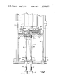
- FIG. 6 shows a cross sectional view along 6--6 of FIG. 1 showing the Y drive and the theta drive of the present invention.
- FIG. 7 shows a cross-sectional view along 7--7 of FIG. 1 showing the X drive and the Y drive of the present invention
- FIG. 8 shows an exploded perspective view of the base, X, Y and theta plates.
- FIG. 1 shows a partially cut-away top plan view of the bottom three of the nested plates of the present invention.
- the mating surfaces of these three plates, 10, 12 and 14, are flat and are impregnated with a solid lubricant such as Teflon available from the Michiana Impreglon Center, Dowagiac, Mich.
- the solid lubricant permits the three plates to slide freely with respect to each other in a high vacuum environment.
- the top face of the Y plate 14 and the bottom of the theta plate not shown in FIG. 1, but shown in FIG. 2, are impregnated with a solid lubricant and are free to slide with respect to each other.
- the X plate is constrained to move left to right in the figure (X direction).
- the limits of motion of the X plate 12 to the left in the figure is represented by dotted line 16.
- the X plate may move a similar distance to the right in the figure.
- the Y plate is constrained to move in the vertical direction in the figure (Y direction).
- the length of travel in the vertical direction is denoted by dotted line 46
- the plate 14 may move a similar distance downward in the figure.
- Y aligned lateral aperture 20 having two wing slots 40 and 42.
- capstan 24 Mounted in aperture 20 and connected to a Y drive shaft discussed infra, is capstan 24. Looped about capstan 24 is metallic band 38 which is connected at its opposite ends 48, 50 to Y plate 14. The connections are made to the plate 14 in the wing slots 40 and 42. The metallic band 30 is maintained under tension by spring 44.
- the center of the Y plate 14 has been cut away to expose a T-shaped slot 52 having an X aligned lateral aperture 54 and a Y aligned central aperture 56.
- X aligned lateral aperture Mounted in X aligned lateral aperture is X capstan 26, which is mounted on an X drive shaft, discussed infra.
- Looped around the capstan 26 is a metallic band 30, which is connected at each of its ends 32 and 34 to X plate 12. The connections are made in lateral wing slots 58, 60 of X aligned lateral aperture 54.
- the band 30 is maintained under tension by spring 36.
- FIG. 6 Shown in the Y aligned central aperture 56 is theta drive shaft 28 and universal joint 22 connected thereto. See FIG. 6. These will be discussed in more detail infra; however the theta drive shaft fixedly couples to theta plate 62 shown in FIG. 2
- FIG. 2 shows a bottom plan view of the theta plate.
- Theta drive shaft 28 couples to shaft 64 mounted in theta plate 62.
- the theta plate is essentially circular in shape having flattened upper and lower edges.
- FIG. 3 shows a top plan view of the Y plate.
- the Y plate's shape is essentially that of an elongated hexagon. Shown in the figure are the Y aligned lateral aperture 20 and lateral wing slots 40 and 42. The figure also shows capstan 24, metallic band 38 connected at its opposite ends 48 and 50 to Y plate 14. Spring 44 maintains the metallic band 38 under tension.
- a bearing 66 is mounted in the Y plate. Theta drive shaft 28 is slidably mounted in this bearing 66. The freedom of movement of the Y plate 14 is limited to the Y direction as indicated by arrows Y--Y in the figure.
- FIG. 4A shows a top plan view of the X plate 12.
- Y shaft bearing 70 mounted in the plate.
- Y drive shaft 68 is rotatably mounted in this bearing 70.
- the bearing 70 forces Y drive shaft 68 to move with the X plate 12.
- T-shaped aperture 52 shown in this figure.
- the X capstan 26 (FIG. 1) when rotated, causes the X plate to slide in the X direction, as shown by the arrows X--X in the figure.
- FIG. 4B is a section along B--B of FIG. 4A. Shown in the figure are cross sections of X plate 12 and Y plate 14. Y plate 14 is slidably mounted on top of X plate 12 and constrained to move in the Y direction by lateral guides 72 and 74. These guides 72, 74 contain additional coupling members which protrude into slots 76 and 78 mounted on the sides of Y plate 14. These additionally restrain the motion of the Y plate in the vertical direction.
- FIG. 4B Also shown in FIG. 4B are the cross sections of Y aligned lateral aperture 20 and wing slot 40 mounted in Y plate 14.
- the cross section of the X plate shows aligned lateral aperture 54, Y aligned central aperture 56 and wing slots 58 and 60.
- FIG. 5 shows a top plan view of the base plate 10.
- the base plate 10 includes lateral guides 80 and 82 between which the X plate 12 is mounted and by which the X plate 12 is constrained to slide in the X direction (X--X in the figure).
- the base plate also includes a X-Y aligned central aperture 84, which provides for movement of both the theta drive shaft 28 and the Y drive shaft 68. The theta drive shaft 28 is allowed to move in both the X and Y directions.
- X-Y aligned central aperture 84 is extended a small distance 86 to the right to allow for movement of the Y drive shaft in this direction.
- X drive shaft bearing 90 Mounted in base plate 10 are X drive shaft bearing 90. Mounted therein is X drive shaft 92. The bearing 90 allows rotational motion of shaft 92 but fixes the freedom of motion of drive shaft 92 in the X/Y plane as base plate 10 is fixedly mounted. See FIG. 6.
- lightening hole 88 Also shown in the figure is lightening hole 88.
- FIG. 6 is a section along 6--6 of FIG. 1.
- Base plate 10 is fixedly mounted to vacuum chamber wall 166 by bolts 162 coupling the base plate 10 to a beam member 164 which is in turn fixedly attached to the chamber wall 166. While there is only one such bolt 162 shown in the figure, three others not shown attach the plate 10 to chamber walls 166 and 170 at the other three corners of base plate 10.
- X plate 12 is slidably mounted on base plate 10 and Y plate 14 is slidably mounted on X plate 12.
- Theta plate 62 is mounted on Y plate 14.
- a wafer 122 mounted atop theta plate 62.
- an electron beam device 124 Shown to the right in the figure is a portion of a shuttle 128 which will be discussed in reference to FIG. 7.
- Theta drive shaft 28 is mounted in bearing 66 and is fixedly coupled to theta plate 62.
- the bearing 66 forces theta plate 62 to move with Y plate 14.
- theta plate 62 is similarly constrained to move in both the X and Y directions.
- Theta drive shaft 28 couples to a universal joint 22, which in turn couples to the lower portion 176 of the drive shaft 28.
- the lower portion 176 couples to a bellows coupling 144.
- a connecting shaft 178 couples to the bellows 144 and is mounted in ferro-fluidic seal mounted in chamber bottom plate 168.
- Ferro-fludic seal 146 is of a type EMB-188-L-N-130 available from Ferrofluidics Corporation located in Nashua, N.H. This seal prevents the escape of vacuum through the seal while permitting either up and down or rotational motion of a drive shaft coupled there-through.
- the connecting shaft 178 couples through a lower bellows 108 into a motor mounting plate 172.
- Bracket 150 is fixedly mounted on connecting shaft 178 below bottom plate 168. Pivotally coupled to bracket 150 is a liftfork 148 at pivot 152. Liftfork 148 is in turn connected to a pivot 154, which is pivotally mounted to the motor mounting plate by a mounting not shown. Lever arm 155 is connected to pivot 154 and is also pivotally connected to shaft 158 at pivot 156. Shaft 158 is slidably mounted in air cylinder hydraulic drive motor 160. When motor 160 forces shaft 158 downward in the figure, lever arm 155 pivots liftfork 148 upwards driving drive shaft 28 upward.
- Y drive shaft 68 is rotatably mounted in bearing 70.
- This shaft 66 couples to a universal joint 94, which is coupled to a lower Y drive shaft 180.
- Lower shaft 180 couples to a bellows coupling 102.
- a second connecting shaft 182 is mounted in a second ferro-fluidic seal 106 mounted in bottom plate 168 and is coupled to bellows coupling 102.
- Ferro-fluidic seal 106 has the same function as seal 104 discussed above.
- the shaft is then coupled to a lower bellows coupling 110 to a Y drive motor 114 fixedly mounted on motor mounting plate 172.
- the Y drive motor causes the Y drive shaft 68 to rotate in a clockwise or a counter clockwise direction. This rotation, in turn, causes the Y capstan 24 to rotate in a similar clockwise or counter clockwise direction, thereby causing the metallic band coupled thereto to move the Y plate 14 in the Y direction as shown in FIGS. 1 and 3.
- lightening hole 88 Also shown in the figure are lightening hole 88, X-Y aligned central aperture 84 with extension 86 and Y aligned central aperture 56.
- the length of lower shafts 176 and 180 is chosen such that the deflecting angle at maximum is approximately 7°. This causes little distortion of the bellows coupling on deflection.
- FIG. 7 is a section along 7-7 of FIG. 1.
- Three electron beam devices 124 are mounted above the nested plates 10, 12, 14 and 62
- a wafer shuttle comprising a left shuttle track 126, a right shuttle track 128, a shuttle capstan 130, a shuttle drive shaft 132, a shuttle bellows coupling 134, and a shuttle ferro-fluidic seal 136 is mounted below the electron beam devices 124 and above the nested plates 10, 12, 14 and 62. Not shown is a shuttle motor.
- the figure also shows two positions for theta plate 62. To the left in the figure, theta plate 62 is shown in a "up" position.
- wafer 122 clears the shuttle 126 This allows the shuttle to be moved relative to the wafer such as to be withdrawn from under the wafer to retrieve, for example, a second wafer for subsequent loading of the second wafer onto the theta plate 60.
- theta plate 62 is in the "lowered" position In this position, the wafer 122 rests on the right shuttle 128.
- the shuttle 128 "carries" the wafer 122 for loading and unloading purposes.
- Metallic band 38 loop mounts on Y capstan 24.
- Band 38 comprises two substantially equal portions, a portion 116 having spaced upper and lower bands and a portion 118 having a central band arranged between the spaced upper and lower bands 116. This mounting and arrangement permits the metallic "band" to be wound or unwound on the capstan without interference between the leftmost portion 118 and rightmost portion 116.
- the band connections 50 and 48 to the Y plate 14.
- the rightmost connection 50 is a fixed coupling to Y plate 14, while the leftmost coupling 44 is a spring mounted coupling to Y plate 14.
- the spring 44 maintains metallic band 38 under tension.
- the X band 30 (FIG. 1) is identical to Y band 38.
- the Y drive shaft 68 is rotably mounted in bearing 70 and couples to a universal joint 94.
- a lower Y drive shaft 180 is coupled to joint 94 and a third bellows coupling 102, as discussed above.
- Lower theta drive shaft 176 is mounted directly behind the lower Y drive shaft 180 in the figure.
- X capstan 26 is mounted on X drive shaft 92.
- Shaft 92 is rotatably mounted in bearing 90.
- the X drive shaft 92 in contrast to the other two drive shafts, 28 and 68, contains no universal joints because of its fixed mounting in the fixed plate 10. However, it, too, couples to a bellows coupling 100.
- a connecting shaft 184 is mounted in a third ferro-fluidic seal 104 and is coupled to bellows 100 and 109. This is in turn coupled to X drive motor 112, which is fixedly mounted on motor mounting plate 172.
- Ferro-fluidic seals 104, 106, 136 and 146 are mounted in bottom plate 168.
- Lateral guides 80 and 82 are mounted on base plate 10 and constrain motion of the X plate 12 to the X direction.
- the theta plate 62 is constrained to move with the Y plate in the X-Y plane by virtue of theta shaft 28 mounting in bearing 66.
- the theta drive shaft 28 has a freedom of movement in the vertical or Z direction relative to the X/Y plane.
- the pivoting of liftfork 148 by motor 160 drives the theta plate 62 in the Z direction.
- Bellows couplings 102 and 104 permit the lower theta and lower Y drive shafts 176 and 180 to deflect at a small angle while permitting, in the case of the Y drive shaft 180, the Y drive motor 114 to rotate the shaft 180 in a clockwise or a counterclockwise direction.
- Universal joints 22 and 94 in turn permit the upper portions of the drive shafts 28 and 68 to remain vertically aligned.
- FIG. 8 shows an exploded perspective view of the base X, Y and theta plates.
Landscapes
- Chemical & Material Sciences (AREA)
- Analytical Chemistry (AREA)
- Electron Beam Exposure (AREA)
- Container, Conveyance, Adherence, Positioning, Of Wafer (AREA)
Abstract
Description
Claims (6)
Priority Applications (7)
| Application Number | Priority Date | Filing Date | Title |
|---|---|---|---|
| US06/489,666 US4516029A (en) | 1983-04-28 | 1983-04-28 | E beam stage with below-stage X-Y drive |
| GB08409804A GB2139412B (en) | 1983-04-28 | 1984-04-16 | An electron beam x-y coordinate positioning stage with below stage drive |
| FR8406728A FR2550380B1 (en) | 1983-04-28 | 1984-04-27 | PLATE FOR POSITIONING IN X-Y COORDINATES FOR ELECTRON BEAM WITH DRIVE FROM BELOW |
| AU27453/84A AU560020B2 (en) | 1983-04-28 | 1984-04-27 | Positioning in electron beam apparatus |
| JP59086053A JPS59207625A (en) | 1983-04-28 | 1984-04-27 | Electron beam x-y coordinates position determining stage |
| DE19843415847 DE3415847A1 (en) | 1983-04-28 | 1984-04-27 | ELECTRON BEAM X-Y COORDINATE POSITIONING STAGE |
| CA000452995A CA1224852A (en) | 1983-04-28 | 1984-04-27 | E beam stage with below-stage x-y drive |
Applications Claiming Priority (1)
| Application Number | Priority Date | Filing Date | Title |
|---|---|---|---|
| US06/489,666 US4516029A (en) | 1983-04-28 | 1983-04-28 | E beam stage with below-stage X-Y drive |
Publications (1)
| Publication Number | Publication Date |
|---|---|
| US4516029A true US4516029A (en) | 1985-05-07 |
Family
ID=23944773
Family Applications (1)
| Application Number | Title | Priority Date | Filing Date |
|---|---|---|---|
| US06/489,666 Expired - Lifetime US4516029A (en) | 1983-04-28 | 1983-04-28 | E beam stage with below-stage X-Y drive |
Country Status (7)
| Country | Link |
|---|---|
| US (1) | US4516029A (en) |
| JP (1) | JPS59207625A (en) |
| AU (1) | AU560020B2 (en) |
| CA (1) | CA1224852A (en) |
| DE (1) | DE3415847A1 (en) |
| FR (1) | FR2550380B1 (en) |
| GB (1) | GB2139412B (en) |
Cited By (9)
| Publication number | Priority date | Publication date | Assignee | Title |
|---|---|---|---|---|
| US4746800A (en) * | 1986-03-27 | 1988-05-24 | Asm Lithography B.V. | Positioning device comprising a z-manipulator and a θ-manipulator |
| US4777372A (en) * | 1986-05-08 | 1988-10-11 | Micrion Limited Partnership | Right angle driving |
| WO1988009945A1 (en) * | 1987-06-04 | 1988-12-15 | Renishaw Plc | Positioning apparatus particularly for use in a vacuum environment |
| US4891526A (en) * | 1986-12-29 | 1990-01-02 | Hughes Aircraft Company | X-Y-θ-Z positioning stage |
| GB2274196A (en) * | 1993-01-06 | 1994-07-13 | Kore Tech Ltd | Manipulating a sample |
| EP0654813A1 (en) * | 1993-10-28 | 1995-05-24 | Mitsubishi Denki Kabushiki Kaisha | Electron beam drawing apparatus and method of drawing with such apparatus |
| US5438206A (en) * | 1993-06-02 | 1995-08-01 | Matsushita Electric Industrial Co., Ltd. | Positioning device |
| US20100012860A1 (en) * | 2008-07-17 | 2010-01-21 | All Welding Technologies Ag | Electron beam processing device |
| US20240329544A1 (en) * | 2023-03-30 | 2024-10-03 | Gudeng Equipment Co., Ltd. | Inner pod holding device conducive to reducing dust contamination and optical inspection apparatus for inner pod |
Families Citing this family (1)
| Publication number | Priority date | Publication date | Assignee | Title |
|---|---|---|---|---|
| DE19531676C1 (en) * | 1995-08-29 | 1996-11-14 | Hesse Gmbh | Measurement of guideways offsets in multiaxis positioning systems for compensation purposes |
Citations (7)
| Publication number | Priority date | Publication date | Assignee | Title |
|---|---|---|---|---|
| US2860933A (en) * | 1955-08-04 | 1958-11-18 | Bell Telephone Labor Inc | Bearing for device for transmitting rotary motion into a sealed chamber |
| US3155383A (en) * | 1962-10-11 | 1964-11-03 | Link Division Of General Prec | Precision positioning apparatus |
| US3428387A (en) * | 1963-04-10 | 1969-02-18 | Watson W & Sons Ltd | Friction driven microscope stages |
| US3790155A (en) * | 1972-07-17 | 1974-02-05 | Radiant Energy Systems | X-y table for vacuum systems |
| US3881369A (en) * | 1973-12-26 | 1975-05-06 | Xerox Corp | Bi-axial positioner |
| US4030615A (en) * | 1974-08-06 | 1977-06-21 | Kernforschungsanlage Julich Gesellschaft Mit Beschrankter Haftung | Manipulator for movement of articles in a controlled environment chamber, especially a high vacuum chamber |
| US4097116A (en) * | 1975-11-10 | 1978-06-27 | Nippon Kogaku K.K. | Microscope stage |
-
1983
- 1983-04-28 US US06/489,666 patent/US4516029A/en not_active Expired - Lifetime
-
1984
- 1984-04-16 GB GB08409804A patent/GB2139412B/en not_active Expired
- 1984-04-27 FR FR8406728A patent/FR2550380B1/en not_active Expired
- 1984-04-27 AU AU27453/84A patent/AU560020B2/en not_active Ceased
- 1984-04-27 DE DE19843415847 patent/DE3415847A1/en not_active Withdrawn
- 1984-04-27 JP JP59086053A patent/JPS59207625A/en active Pending
- 1984-04-27 CA CA000452995A patent/CA1224852A/en not_active Expired
Patent Citations (7)
| Publication number | Priority date | Publication date | Assignee | Title |
|---|---|---|---|---|
| US2860933A (en) * | 1955-08-04 | 1958-11-18 | Bell Telephone Labor Inc | Bearing for device for transmitting rotary motion into a sealed chamber |
| US3155383A (en) * | 1962-10-11 | 1964-11-03 | Link Division Of General Prec | Precision positioning apparatus |
| US3428387A (en) * | 1963-04-10 | 1969-02-18 | Watson W & Sons Ltd | Friction driven microscope stages |
| US3790155A (en) * | 1972-07-17 | 1974-02-05 | Radiant Energy Systems | X-y table for vacuum systems |
| US3881369A (en) * | 1973-12-26 | 1975-05-06 | Xerox Corp | Bi-axial positioner |
| US4030615A (en) * | 1974-08-06 | 1977-06-21 | Kernforschungsanlage Julich Gesellschaft Mit Beschrankter Haftung | Manipulator for movement of articles in a controlled environment chamber, especially a high vacuum chamber |
| US4097116A (en) * | 1975-11-10 | 1978-06-27 | Nippon Kogaku K.K. | Microscope stage |
Cited By (11)
| Publication number | Priority date | Publication date | Assignee | Title |
|---|---|---|---|---|
| US4746800A (en) * | 1986-03-27 | 1988-05-24 | Asm Lithography B.V. | Positioning device comprising a z-manipulator and a θ-manipulator |
| US4777372A (en) * | 1986-05-08 | 1988-10-11 | Micrion Limited Partnership | Right angle driving |
| US4891526A (en) * | 1986-12-29 | 1990-01-02 | Hughes Aircraft Company | X-Y-θ-Z positioning stage |
| WO1988009945A1 (en) * | 1987-06-04 | 1988-12-15 | Renishaw Plc | Positioning apparatus particularly for use in a vacuum environment |
| GB2274196A (en) * | 1993-01-06 | 1994-07-13 | Kore Tech Ltd | Manipulating a sample |
| US5438206A (en) * | 1993-06-02 | 1995-08-01 | Matsushita Electric Industrial Co., Ltd. | Positioning device |
| EP0654813A1 (en) * | 1993-10-28 | 1995-05-24 | Mitsubishi Denki Kabushiki Kaisha | Electron beam drawing apparatus and method of drawing with such apparatus |
| US20100012860A1 (en) * | 2008-07-17 | 2010-01-21 | All Welding Technologies Ag | Electron beam processing device |
| US8076658B2 (en) * | 2008-07-17 | 2011-12-13 | Global Beam Technologies Ag | Electron beam processing device |
| US20240329544A1 (en) * | 2023-03-30 | 2024-10-03 | Gudeng Equipment Co., Ltd. | Inner pod holding device conducive to reducing dust contamination and optical inspection apparatus for inner pod |
| US12306550B2 (en) * | 2023-03-30 | 2025-05-20 | Gudeng Equipment Co., Ltd. | Inner pod holding device conducive to reducing dust contamination and optical inspection apparatus for inner pod |
Also Published As
| Publication number | Publication date |
|---|---|
| FR2550380A1 (en) | 1985-02-08 |
| FR2550380B1 (en) | 1988-03-11 |
| AU560020B2 (en) | 1987-03-26 |
| GB2139412B (en) | 1986-08-06 |
| AU2745384A (en) | 1984-11-01 |
| GB2139412A (en) | 1984-11-07 |
| CA1224852A (en) | 1987-07-28 |
| GB8409804D0 (en) | 1984-05-23 |
| JPS59207625A (en) | 1984-11-24 |
| DE3415847A1 (en) | 1984-10-31 |
Similar Documents
| Publication | Publication Date | Title |
|---|---|---|
| US12263587B2 (en) | Dual arm robot | |
| US4516029A (en) | E beam stage with below-stage X-Y drive | |
| US6132165A (en) | Single drive, dual plane robot | |
| US10029363B2 (en) | Dual arm robot | |
| US8777547B2 (en) | Systems, apparatus and methods for transporting substrates | |
| US5765983A (en) | Robot handling apparatus | |
| JP6123104B2 (en) | Substrate transfer apparatus having different holding end effectors | |
| EP1219394B1 (en) | Articulated robot | |
| JP3558345B2 (en) | Articulated arm transfer device | |
| US5954472A (en) | Batch loader arm | |
| JP2012039125A (en) | Robot for handling semiconductor wafers | |
| US20240042595A1 (en) | Dual robot including splayed end effectors and systems and methods including same | |
| WO2011065325A1 (en) | Conveyance arm and conveyance robot with same | |
| JP4231552B2 (en) | Object transfer device with wide wrist and bending arm | |
| US20080121064A1 (en) | Robot with belt-drive system | |
| TW202333914A (en) | Substrate transfer robot for transferring substrate in vacuum chamber | |
| TW202333923A (en) | Substrate transfer robot for transferring substrate in vacuum chamber | |
| US20010033788A1 (en) | Dual multitran robot arm | |
| US12234106B1 (en) | Apparatus for transferring substrate in vaccum chamber | |
| JP2919065B2 (en) | Transfer device | |
| JP4116675B2 (en) | Coaxial drive loader arm | |
| JPH0526618B2 (en) | ||
| KR102942092B1 (en) | Apparatus for transferring substrate in vaccum chamber | |
| JP2000243809A (en) | Articulated robot device | |
| JP2889938B2 (en) | Wafer carrier transfer device |
Legal Events
| Date | Code | Title | Description |
|---|---|---|---|
| AS | Assignment |
Owner name: CONTROL DATA CORPORATION, 8100-34TH AVE., SO., MIN Free format text: ASSIGNMENT OF ASSIGNORS INTEREST.;ASSIGNOR:TUCKER, THEODORE W.;REEL/FRAME:004155/0188 Effective date: 19830421 Owner name: CONTROL DATA CORPORATION,MINNESOTA Free format text: ASSIGNMENT OF ASSIGNORS INTEREST;ASSIGNOR:TUCKER, THEODORE W.;REEL/FRAME:004155/0188 Effective date: 19830421 |
|
| STCF | Information on status: patent grant |
Free format text: PATENTED CASE |
|
| FEPP | Fee payment procedure |
Free format text: PAYOR NUMBER ASSIGNED (ORIGINAL EVENT CODE: ASPN); ENTITY STATUS OF PATENT OWNER: LARGE ENTITY |
|
| FPAY | Fee payment |
Year of fee payment: 4 |
|
| FEPP | Fee payment procedure |
Free format text: PAYER NUMBER DE-ASSIGNED (ORIGINAL EVENT CODE: RMPN); ENTITY STATUS OF PATENT OWNER: LARGE ENTITY |
|
| AS | Assignment |
Owner name: ST. CLAIR INTELLECTUAL PROPERTY CONSULTANTS, INC. Free format text: ASSIGNMENT OF ASSIGNORS INTEREST.;ASSIGNOR:CERIDIAN CORPORATION;REEL/FRAME:006276/0183 Effective date: 19920727 |
|
| FEPP | Fee payment procedure |
Free format text: PAYOR NUMBER ASSIGNED (ORIGINAL EVENT CODE: ASPN); ENTITY STATUS OF PATENT OWNER: LARGE ENTITY |
|
| REMI | Maintenance fee reminder mailed | ||
| REMI | Maintenance fee reminder mailed | ||
| FPAY | Fee payment |
Year of fee payment: 8 |
|
| SULP | Surcharge for late payment | ||
| FPAY | Fee payment |
Year of fee payment: 12 |
|
| FEPP | Fee payment procedure |
Free format text: PAYER NUMBER DE-ASSIGNED (ORIGINAL EVENT CODE: RMPN); ENTITY STATUS OF PATENT OWNER: LARGE ENTITY Free format text: PAYOR NUMBER ASSIGNED (ORIGINAL EVENT CODE: ASPN); ENTITY STATUS OF PATENT OWNER: LARGE ENTITY |
|
| REFU | Refund |
Free format text: REFUND PROCESSED. MAINTENANCE FEE HAS ALREADY BEEN PAID (ORIGINAL EVENT CODE: R160); ENTITY STATUS OF PATENT OWNER: LARGE ENTITY |