US4513475A - Hinges and hinged articles - Google Patents
Hinges and hinged articles Download PDFInfo
- Publication number
- US4513475A US4513475A US06/485,067 US48506783A US4513475A US 4513475 A US4513475 A US 4513475A US 48506783 A US48506783 A US 48506783A US 4513475 A US4513475 A US 4513475A
- Authority
- US
- United States
- Prior art keywords
- axis
- hinge
- coupling
- pivot
- projections
- Prior art date
- Legal status (The legal status is an assumption and is not a legal conclusion. Google has not performed a legal analysis and makes no representation as to the accuracy of the status listed.)
- Expired - Lifetime
Links
- 230000008878 coupling Effects 0.000 claims abstract description 62
- 238000010168 coupling process Methods 0.000 claims abstract description 62
- 238000005859 coupling reaction Methods 0.000 claims abstract description 62
- 238000005452 bending Methods 0.000 claims description 32
- 230000013011 mating Effects 0.000 claims description 6
- 238000010276 construction Methods 0.000 description 2
- 230000004048 modification Effects 0.000 description 2
- 238000012986 modification Methods 0.000 description 2
- 230000001154 acute effect Effects 0.000 description 1
- 230000006978 adaptation Effects 0.000 description 1
- 230000009286 beneficial effect Effects 0.000 description 1
Images


Classifications
-
- E—FIXED CONSTRUCTIONS
- E05—LOCKS; KEYS; WINDOW OR DOOR FITTINGS; SAFES
- E05D—HINGES OR SUSPENSION DEVICES FOR DOORS, WINDOWS OR WINGS
- E05D3/00—Hinges with pins
- E05D3/06—Hinges with pins with two or more pins
- E05D3/10—Hinges with pins with two or more pins with non-parallel pins
-
- B—PERFORMING OPERATIONS; TRANSPORTING
- B21—MECHANICAL METAL-WORKING WITHOUT ESSENTIALLY REMOVING MATERIAL; PUNCHING METAL
- B21D—WORKING OR PROCESSING OF SHEET METAL OR METAL TUBES, RODS OR PROFILES WITHOUT ESSENTIALLY REMOVING MATERIAL; PUNCHING METAL
- B21D5/00—Bending sheet metal along straight lines, e.g. to form simple curves
- B21D5/04—Bending sheet metal along straight lines, e.g. to form simple curves on brakes making use of clamping means on one side of the work
- B21D5/042—With a rotational movement of the bending blade
-
- E—FIXED CONSTRUCTIONS
- E05—LOCKS; KEYS; WINDOW OR DOOR FITTINGS; SAFES
- E05Y—INDEXING SCHEME ASSOCIATED WITH SUBCLASSES E05D AND E05F, RELATING TO CONSTRUCTION ELEMENTS, ELECTRIC CONTROL, POWER SUPPLY, POWER SIGNAL OR TRANSMISSION, USER INTERFACES, MOUNTING OR COUPLING, DETAILS, ACCESSORIES, AUXILIARY OPERATIONS NOT OTHERWISE PROVIDED FOR, APPLICATION THEREOF
- E05Y2900/00—Application of doors, windows, wings or fittings thereof
- E05Y2900/20—Application of doors, windows, wings or fittings thereof for furniture, e.g. cabinets
Definitions
- This invention relates to hinges and hinged articles.
- this invention relates to a bending machine having a hinge in accordance with this invention.
- hinges provided by the present invention have broader application such as to other bending machines and also for doors and cupboards among other things.
- the present invention provides a hinged article comprising a first body, a second body, and hinge means interconnecting the first and second bodies and defining a hinge line and wherein the hinge means includes a hinge comprising a first member mounted to the first body and arranged to pivot about a first pivot axis; a projection of which first pivot axis is inclined to said hinge line; and coupling means articulating the first member to the second body.
- the present invention also provides a hinged article comprising a first body, a second body, and hinge means interconnecting the first and second bodies and defining a hinge line and wherein the hinge means includes a hinge comprising a first member mounted to the first body and arranged to pivot about a first pivot axis; a projection of which first pivot axis is inclined to said line; and a coupling interconnecting the first member and the second body and at least in part constraining the bodies to hinge at least substantially about said line and compensating for the inclination of said first pivot axis.
- the present invention also provides a hinged article comprising a first body, a second body, hinge means interconnecting the first and second bodies and constraining said bodies to hinge about a hinge line and wherein the hinge means includes a hinge comprising a first member pivotally mounted to the first body about a first pivot axis; a projection of which first pivot axis intersects said hinge line at an angle and at a point; and a coupling articulating the first member to the second body and permitting two degrees of freedom of relative rotation about said point.
- the present invention also provides a hinged article comprising a first body, a second body, hinge means interconnecting the first and second bodies; and wherein the hinge means includes a hinge which comprises a first member pivotally mounted to the first body to pivot about a first pivot axis, and a coupling attached to the first member and to the second body and defining a second pivot axis about which the first member can pivot; and constructed and arranged such that projections of said first pivot axis and said second pivot axis of said hinge intersect at a point, about said point said second pivot axis of said hinge is able to pivot, whereby a hinge line about which said bodies can hinge is defined which extends through said point and wherein a projection of said first pivot axis of said hinge intersects said hinge line at an angle.
- the present invention also provides a hinge comprising means defining a first pivot axis, first mounting means for mounting said first pivot axis to a first body with said first pivot axis inclined to a hinge line, a first member adapted to pivot about said first pivot axis, and a coupling means for articulating the first member to a second body hingeable about said hinge line.
- the present invention also provides a hinge comprising means defining a first pivot axis, first mounting means for mounting said first pivot axis to a first body with said first pivot axis inclined to a hinge line, a first member adapted to pivot about said first pivot axis, and a coupling for interconnecting the first member to a second body, at least in part constraining the bodies to hinge at least substantially about said line and for compensating for the inclination of said first pivot axis.
- the present invention also provides a hinge comprising means defining a first pivot axis, first mounting means for mounting said first pivot axis to a first body with said first pivot axis inclined to a hinge line, a first member adapted to pivot about said first pivot axis, and a coupling for articulating the first member to a second body and permitting two degrees of freedom of relative rotation about the point at which said first pivot axis intersects said hinge line.
- the present invention also provides a hinge comprising means defining a first pivot axis, first mounting means for mounting said first pivot axis to a first body with said first pivot axis inclined to a hinge line, a first member adapted to pivot about said first axis, and a coupling for articulating the first member to a second body and defining a second pivot axis about which the first member can pivot; and constructed and arranged such that a projection of said first pivot axis and said second pivot axis intersect at a point and, in use, at said hinge line, and about which point said second pivot axis is able to pivot.
- said second pivot axis is able to rotate about a third pivot axis fixed relative to said second body and which intersects said point.
- the first member is mounted for reciprocating sliding movement along said first pivot axis.
- said coupling comprises a second member pivotally attached to said first member to pivot about a second pivot axis, and pivotally attached to said second body to pivot about a third pivot axis.
- projections of said third pivot axis do not intersect said hinge line.
- projections of said second pivot axis do not intersect with projections of said third pivot axis.
- said coupling comprises a concave partial spherical surface carried by said first member and a mating convex partial spherical surface carried by said second body and wherein the centres about which the partial spherical surfaces are formed are coincident at said point.
- parallel spaced apart guide means is positioned on opposite sides of the convex partial spherical surface to guide the motion of said first member.
- said coupling comprises a second member mounted to said first member to rotate about said second axis and to said second body to rotate about said third axis.
- said coupling comprises a concave partial cylindrical surface carried by said second member and a mating convex partial cylindrical surface carried by said second body and wherein the axes about which the partial cylindrical surfaces are formed intersect said point and it is preferred that parallel spaced apart guide means is positioned on opposite sides of the convex partial cylindrical surface to guide the motion of said second member.
- said third pivot axis is inclined at an acute angle to said second pivot axis.
- the present invention has particular but not exclusive application to bending machines.
- the present invention also provides a hinged article in accordance with this invention which is a bending machine.
- hinges in accordance with this invention may, of themselves alone, define only a point of pivoting rather than a line and may need to be associated with one or more other hinges to define a line.
- Those one or more other hinges may be hinges in accordance with this invention and may in certain circumstances be conventional hinges.
- first and second bodies When applied to bending machines, it will be most usual for the first and second bodies to have planar work faces which in one position of the machine will lie in a plane and the hinge line will also lie in that plane. However, some bending machines may have the work faces lying in parallel planes and in other machines the hinge line may lie above the first mentioned plane and/or may be relatively more adjacent one of the work surfaces than the other of the work surfaces. Further, by selecting hinges in accordance with this invention which have axes located in particular dispositions perturbations of the rotation of one of the work surfaces can be obtained which will be beneficial in certain bending machines.
- FIG. 1 is an elevational view of a conventional hinge applied to a bending machine
- FIG. 2 is an end view of the conventional hinge applied to a bending machine in one position
- FIG. 3 is an end view of the conventional hinge applied to a bending machine in another position
- FIG. 4 is an elevational schematic representation of a hinge in accordance with this invention in a bending machine
- FIG. 5 is an end view schematic representation of a hinge in accordance with this invention in one position
- FIG. 6 is an end view schematic representation of a hinge in accordance with this invention in another position
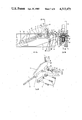
- FIG. 7 is an exploded perspective view of a hinge in accordance with this invention which will hereinafter be referred to as "the spherical external hinge"
- FIG. 8A is an elevational view of the spherical external hinge in a bending machine in one position
- FIG. 8B is a cross-sectional view on line 8B--8B in FIG. 8A,
- FIGS. 9A, 10A, 11A and 12A are elevational view of the spherical external hinge in a bending machine in other positions
- FIGS. 9B, 10B, 11B and 12B are cross-sectional views on lines axially corresponding to line 8B--8B in FIG. 8A but in respect of said other positions shown in FIGS. 9A, 10A, 11A and 12A,
- FIG. 13 is an exploded perspective view of a hinge in accordance with this invention which will hereinafter be referred to as "the spherical internal hinge"
- FIG. 14A is an elevational view of the spherical internal hinge in a bending machine in one position
- FIG. 14B is a cross-sectional view on line 14B--14B in FIG. 14A,
- FIG. 15 is an exploded perspective view of a hinge in accordance with this invention which will hereinafter be referred to as "the cranked hinge"
- FIG. 16A is an elevational view of the cranked hinge in a bending machine in one position
- FIG. 16B is a cross-sectional view on line 16B--16B in FIG. 16A,
- FIG. 17 is an elevational view of a part of the cranked hinge
- FIG. 18 is an exploded perspective view of a hinge in accordance with this invention which will hereinafter be referred to as "the cylindrical hinge"
- FIG. 19A is an elevational view of the cylindrical hinge in a bending machine in one position
- FIG. 19B is a cross-sectional view on line 19B--19B in FIG. 19A,
- FIG. 20 is an exploded perspective view of a hinge in accordance with this invention which will hereinafter be referred to as "the trunnion hinge"
- FIG. 21A is an elevational view of the trunnion hinge in a bending machine in one position
- FIG. 21B is a cross-sectional view on line 21B--21B in FIG. 21A,
- FIG. 22 is a schematic representation of a bending machine using a number of the trunnion hinge
- FIG. 23 is an end view of the machine depicted in FIG. 22,
- FIG. 24A is an elevational view of a hinge in accordance with this invention which will hereinafter be referred to as "the modified trunnion hinge" in a bending machine, and
- FIG. 24B is an end view of a bending machine showing positional relationships obtainable by use of the modified trunnion hinge.
- the present invention is easily considered from the point of view of its application in bending machines of the type shown in Australian Patent Specification No. 506,793.
- FIGS. 1-3 a bending machine having an electromagnet comprised of a pole 3 and bending beam 11 which have work engaging surfaces 81 and 5.
- surface 81 lies in a plane which is the plane of surface 5 as shown in FIG. 3.
- the pole 3 and beam 11 are connected by a hinge 80 of conventional form which comprises a leaf 83 and a support 84 for a pivot pin 86.
- the pivot pin 86 defines a hinge line 87 which lies in the plane of surface 5.
- the surfaces 81 and 5 can move from lying in the plane of surface 5, through 90° to one another to being parallel as in FIG. 2.
- the hinge 80 inevitably projects above the hinge line 87 and bending in the region of the hinge 80 will be limited if not impossible.
- the hinge 80 can be recessed below the hinge line 87 by raising the height of surfaces 81 and 5 as shown by dot line in FIG. 3 but so doing is not practical as the hinge line 87 no longer coincides with the intersection of the planes of the surfaces 81 and 5.
- the present invention provides a number of particular hinges which are illustrated schematically in FIGS. 4-6.
- the hinge 80 is replaced by a hinge 82 which comprises two supports 1 and 2 which are secured to pole 3 by mounting bolts 7.
- the supports 1 and 2 each have a bore which defines a first axis 4 on which is mounted a pivot pin 6.
- the hinge plate 8 is connected to the beam 11 by a coupling 90. Various versions of the coupling 90 will be described hereinafter.
- the plate 8 has lugs 9 and 10 which are bored to be received on the pivot pin 6.
- the first axis 4 lies at an angle Q to the hinge line 87. That angle Q is not critical but for practical reasons will usually be between 10° and 45° with about 20° being most preferred.
- the hinge 82 lies below the surface 5 and as shown in FIG. 5 does not interfere with the surfaces 81 and 5 coming to being parallel.
- the hinge plate 8 is restricted against sliding movement along the first axis 4 and in other instances (FIGS. 20-26) such movement is permitted. Hinges in which such movement is restricted are preferred.
- the coupling 90 serves to compensate for the angle Q and acts to cause the pole 11 to move in the desired path and to restrict against undesired motion.
- FIGS. 7-12 relate to the spherical external hinge.
- the coupling 90 is referenced as 91 and comprises a body 32 which has a partial spheric surface 30 and which is secured to the beam 11 by screws 33 and a partial spheric surface 31 on the hinge plate 8.
- the surfaces 30 and 31 are both centred on a point P which is a point on the hinge line 87 which is intersected by the first axis 4.
- the surfaces 30 and 31 are thus made able to relatively rotate about point P and a second axis 39.
- the spheric surfaces 30 and 31 are maintained in contact for sliding in relative rotation by a bolt 34 which is tapped into the hinge plate 8 at 37 and which has a lock nut 38.
- the bolt 34 is located on the second axis 39 but is not essential for defining that second axis 39 which exists because of the particular geometry of the coupling 91 and not merely because of the existence of the bolt 34.
- the bolt 34 can be dispensed with.
- a spring clip 89 shown by dash line in FIG. 8B might be used in lieu of bolt 34 to retain body 32 and hinge plate 8 in sliding contact at surfaces 30 and 31.
- the bolt 34 is allowed to move in the body 32 by means of a slot 36 in the body 32 and has a head 40 which is located in a recess in body 32.
- Movement of the coupling 91 in consequence of movement of the beam 11 is depicted in detail and can be considered to be a movement from a starting position shown in FIGS. 9A and B, successively through the positions shown in FIGS. 10A and B, FIGS. 11A and B, FIG. 12A and B and culminating in the position shown in FIGS. 8A and B.
- the motion of surface 31 relative to surface 30 is rotation about the point P, but this motion can be considered as two simultaneous rotations: firstly from the starting position shown in FIGS. 9A and B and surface 31 undergoes an anti-clockwise rotation about the second axis 39 relative to surface 30 when viewed in the direction indicated by the arrow Y in FIG. 9A until a maximum anti-clockwise rotated position is reached as shown in FIGS. 11A and B whereafter the surface 31 undergoes a clockwise rotation about the second axis 39 relative to surface 30 until, as is shown in FIGS. 8A and B, the surface 31 has the same relative rotation with respect to surface 30 about the second axis 39 as was shown in FIGS.
- FIGS. 9A and B the surface 31 undergoes an anti-clockwise rotation about axis 88 relative to surface 30 when viewed in the direction indicated by the arrow Z in FIG. 11A which successively increases through FIGS. 9A and B, FIGS. 10A and B, FIGS. 11A and B, FIGS. 12A and B and reaches a maximum as shown in FIGS. 8A and B.
- FIGS. 9A and B-12A and B some parts are not shown for reasons of clarity of depiction.
- FIGS. 13-14 relate to the spherical internal hinge.
- the coupling 90 is referenced 92.
- the coupling 92 is functionally substantially the same as the coupling 91 but in this instance the surface 31 is carried by a body 131 and the surface 30 is located within a body 132.
- the body 131 has a male thread at 41 and is received in a female threaded hole 42 in the hinge plate 8.
- the body 132 has the surface 30 located in a cavity 43.
- the sides of the cavity lying parallel with the beam 11 act as guides 44 for the bolt body 131 and are spaced apart equal to the part 45 of the body 131 plus clearance.
- the bolt 34 and locknut 38 serve a similar function in the spherical internal hinge as in the spherical internal hinge and the head 40 is located in a groove 135. However, the bolt 34 is threaded into the body 131.
- the spherical internal hinge operates similarly as the spherical external hinge but it is to be noted that in addition the guides 44 guide the motion of the body 131.
- FIGS. 15-17 relate to the cranked hinge.
- the coupling 93 comprises a body 73 which is secured to the pole 11 by screws 33.
- the body 73 has a spindle 72 which is located on a third axis 71 and has a circlip groove 70 for a circlip 75.
- a body 68 which has a hole 70 to accommodate the spindle 72 and a spindle 65 which has a circlip groove 66 for a circlip 69.
- the spindle 65 is received in a hole 67 in the hinge plate 8.
- the first axis 4, second axis 39 and third axis 71 intersect at point P.
- the coupling 93 although operating differently to couplings 91 and 92, at least in that body 68 acts as a crank, achieves the desired movement of the beam 11 with respect to the pole 5 without any part of the cranked hinge at any time being within the angle included by surfaces 81 and 5.
- the beam 11 is recessed at 76 to accommodate the body 68 when in the position shown in FIG. 16B.
- the first axis 4 and the second axis 39 are perpendicular and the axis 71 is perpendicular to the hinge line 87. None of this particular geometry is essential in that a change in one angle can be compensated for by a change in another angle.
- the angle U between the second axis 39 and third axis 71 is given by the mathematical expression: ##EQU1##
- FIGS. 18-19 relate to the cylindrical hinge.
- the coupling 90 is referenced 94.
- the coupling 94 although physically somewhat similar to coupling 91 can be considered to be more like the coupling 93 in its manner of operation in that there is a rotation about a third axis 171 rather than a rotation about point P as in the case of the coupling 91.
- the coupling 94 comprises a body 173 which is secured to the beam 11 by screws 33.
- the body 173 has cylindrical surfaces 58 and 60.
- the surface 58 has guides 44 upstanding therefrom parallel to the beam 11.
- the coupling 94 also includes a body 168 which has a cylindrical surface 54 and a planar surface 56.
- the hinge plate 8 has a planar surface 52.
- the coupling 94 is held together by a bolt 51 which passes through hole 57 in the hinge plate 8 and a nut 59 which has a cylindrical surface 53.
- a slot 61 permits movement of the bolt 51 in the body 173.
- the cylindrical surfaces 54, 58, 60 and 53 are all centred on the third axis 171.
- the first axis 4 and second axis 39 are perpendicular and the third axis 171 is perpendicular to the hinge line 87 although this geometry is not essential. Further, the third axis 171 non-essentially lies in the plane of the surface 5. Still further, the first axis 4, second axis 39 and third axis 171 intersect at point P.
- the coupling 94 although operating differently to couplings 91-93 achieves the desired movement of the beam 11 without any part of the cylindrical hinge at any time being within the angle included by surfaces 81 and 5. It is particularly to be noted that the guides 44 prevent sliding of the body 168 in the direction of the third axis 171 and restrict sliding of the body 168 on the body 173 to be rotated relative thereto through an angle 2Q about the third axis 171 while the hinge plate 8 at surface 52 relatively rotates with respect to body 168 about the second axis 39.
- hinges can be made in mirror image form if desired but it is not necessary of any two hinges in a bending machine that one be the mirror image of the other.
- FIGS. 20-22 relate to the trunnion hinge.
- the hinge plate 8 is free to slide a distance 21 along the first axis 4.
- the distance 21 is determined by the geometry of the trunnion hinge as will be explained hereinafter.
- the coupling 95 comprises a body 12 having a hole 16 in which is received a bolt 22 having a tapped end 23 and a bearing surface 18.
- the tapped end 23 is received in a tapped bore 24 in the beam 11 and the bearing surface 18 permits rotation of the body 12 about a third axis 17.
- the body 12 also has a spindle 25 which is internally tapped to receive a screw 15 which passes through a washer 14 to retain the spindle 25 within a hole 26 in the hinge plate 8.
- the hole 26 defines a second axis 39.
- the pole 3 is recessed at 27 to accommodate the bolt 22 when in the position shown in FIG. 21B.
- first axis 4 and the second axis 39 intersect at right angles but, with respect to FIG. 21A, at a point 20 below a plane including surface 5.
- the third axis 17 is displaced a distance "a" represented by 22 from point 20 and point P is here defined as being the intercept of the first axis 4 and a vertical plane including the third axis 17.
- the distance between points 20 and P can be called “c” and that between point P and axis 17 in FIG. 21A can be called “b".
- the angle between "a” and "b” is desirably Q.
- the coupling 95 although operating differently to couplings 91-94 sufficiently approximately achieves the desired movement of the beam 11 for practical purposes without any part of the trunnion hinge at any time being within the angle included by surfaces 81 and 5. It is particularly to be noted that the body 12 rotates about the third axis 17 while the hinge plate relatively rotates about the second axis 39 with respect to the body 12.
- the distance 21 will be equal to 2c and will be equal to 2a tan Q.
- Small but defined perturbations of the rotation of beam 11 about the hinge line 87 may be incorporated into the design of the trunnion hinge; for instance, by altering the distance a, the angle Q, the angle between the first axis 4 and the second axis 39 and between the second axis 39 and the third axis 17.
- FIGS. 24A and 24B show, in schematic form, a portion of the modified trunnion hinge which is the same as the trunnion hinge excepting that the third axis 17 is offset from the second axis 39 by a distance "e" which may be 2.5 mm. That offset results in the motion of the beam 11 in the first 90° of travel being more nearly exact and when the beam 11 and pole 3 are at 180° as shown in dash line in FIG. 24B a gap 2t exists which is suitable for closing a seam 102 in a work piece 103.
- FIGS. 24A and B where the hinge is depicted in broken outline rotated to the 90° and 80° positions, the axes 17 and 39 are respectively referenced 17' and 39', and 17" and 39".
- the distance t equals (e tan Q) and the distance b equals (a/cosQ).
- the distance "d" between axis 17 and bending beam surface 81 is equal to (b-t).
Landscapes
- Engineering & Computer Science (AREA)
- Mechanical Engineering (AREA)
- Pivots And Pivotal Connections (AREA)
- Hinges (AREA)
- Laminated Bodies (AREA)
- Closures For Containers (AREA)
Abstract
Description
Claims (17)
Applications Claiming Priority (2)
| Application Number | Priority Date | Filing Date | Title |
|---|---|---|---|
| AUPF3583 | 1982-04-14 | ||
| AUPF358382 | 1982-04-14 |
Publications (1)
| Publication Number | Publication Date |
|---|---|
| US4513475A true US4513475A (en) | 1985-04-30 |
Family
ID=3769480
Family Applications (1)
| Application Number | Title | Priority Date | Filing Date |
|---|---|---|---|
| US06/485,067 Expired - Lifetime US4513475A (en) | 1982-04-14 | 1983-04-14 | Hinges and hinged articles |
Country Status (4)
| Country | Link |
|---|---|
| US (1) | US4513475A (en) |
| EP (1) | EP0092943B1 (en) |
| AT (1) | ATE19126T1 (en) |
| DE (1) | DE3362881D1 (en) |
Cited By (7)
| Publication number | Priority date | Publication date | Assignee | Title |
|---|---|---|---|---|
| US20040187263A1 (en) * | 2003-03-25 | 2004-09-30 | Hoffman Lawrence Andrew | Multi-axis door hinge and swing-out vertical-lift assembly |
| US20050166363A1 (en) * | 2003-03-25 | 2005-08-04 | Hoffman Lawrence A. | Multi-axis door hinge |
| US20050204511A1 (en) * | 2004-03-17 | 2005-09-22 | Klaus Wohlfarth | Hinge for a motor-vehicle door |
| US20060026797A1 (en) * | 2004-08-04 | 2006-02-09 | Checkpoint Systems, Inc. | Damage resistant antenna mount |
| US20070214606A1 (en) * | 2005-02-11 | 2007-09-20 | Hoffman Lawrence A | Simultaneous, multiple plane opening hinge |
| US20090056074A1 (en) * | 2007-08-28 | 2009-03-05 | Chase Daniel A | Automobile door hinge |
| WO2012051627A1 (en) * | 2010-10-15 | 2012-04-19 | The Parabellum Innovations Corporation | Adaptive rail system for ak-style weapon |
Families Citing this family (1)
| Publication number | Priority date | Publication date | Assignee | Title |
|---|---|---|---|---|
| FR2638985A1 (en) * | 1988-11-14 | 1990-05-18 | Guepratte Pierre | IMPROVED FOLDER WITH INTERMEDIATE HINGES |
Citations (5)
| Publication number | Priority date | Publication date | Assignee | Title |
|---|---|---|---|---|
| US2085616A (en) * | 1935-04-01 | 1937-06-29 | Richard G Voge | Hinge |
| US2178908A (en) * | 1937-10-07 | 1939-11-07 | Hudson Richard John Harrington | Hinge mounting for doors, panels, hatchways, or the like |
| US2225178A (en) * | 1938-02-11 | 1940-12-17 | Detroit Harvester Co | Concealed door hinge |
| US2754537A (en) * | 1953-03-19 | 1956-07-17 | Rose Carl | Hinge structure |
| US3594853A (en) * | 1969-07-28 | 1971-07-27 | Atwood Vacuum Machine Co | Automobile door hinging |
Family Cites Families (1)
| Publication number | Priority date | Publication date | Assignee | Title |
|---|---|---|---|---|
| FR1409898A (en) * | 1964-07-23 | 1965-09-03 | Virtual center of rotation joint |
-
1983
- 1983-04-14 DE DE8383302125T patent/DE3362881D1/en not_active Expired
- 1983-04-14 EP EP83302125A patent/EP0092943B1/en not_active Expired
- 1983-04-14 AT AT83302125T patent/ATE19126T1/en not_active IP Right Cessation
- 1983-04-14 US US06/485,067 patent/US4513475A/en not_active Expired - Lifetime
Patent Citations (5)
| Publication number | Priority date | Publication date | Assignee | Title |
|---|---|---|---|---|
| US2085616A (en) * | 1935-04-01 | 1937-06-29 | Richard G Voge | Hinge |
| US2178908A (en) * | 1937-10-07 | 1939-11-07 | Hudson Richard John Harrington | Hinge mounting for doors, panels, hatchways, or the like |
| US2225178A (en) * | 1938-02-11 | 1940-12-17 | Detroit Harvester Co | Concealed door hinge |
| US2754537A (en) * | 1953-03-19 | 1956-07-17 | Rose Carl | Hinge structure |
| US3594853A (en) * | 1969-07-28 | 1971-07-27 | Atwood Vacuum Machine Co | Automobile door hinging |
Cited By (12)
| Publication number | Priority date | Publication date | Assignee | Title |
|---|---|---|---|---|
| US20040187263A1 (en) * | 2003-03-25 | 2004-09-30 | Hoffman Lawrence Andrew | Multi-axis door hinge and swing-out vertical-lift assembly |
| US20050166363A1 (en) * | 2003-03-25 | 2005-08-04 | Hoffman Lawrence A. | Multi-axis door hinge |
| US7007346B2 (en) * | 2003-03-25 | 2006-03-07 | Lawrence Andrew Hoffman | Multi-axis door hinge and swing-out vertical-lift assembly |
| US7210200B2 (en) | 2003-03-25 | 2007-05-01 | The Hoffman Group, Llc | Multi-axis door hinge |
| US20050204511A1 (en) * | 2004-03-17 | 2005-09-22 | Klaus Wohlfarth | Hinge for a motor-vehicle door |
| US7100245B2 (en) | 2004-03-17 | 2006-09-05 | Klaus Wohlfarth | Hinge for a motor-vehicle door |
| US20060026797A1 (en) * | 2004-08-04 | 2006-02-09 | Checkpoint Systems, Inc. | Damage resistant antenna mount |
| US7168668B2 (en) | 2004-08-04 | 2007-01-30 | Checkpoint Systems, Inc. | Damage resistant antenna mount |
| US20070214606A1 (en) * | 2005-02-11 | 2007-09-20 | Hoffman Lawrence A | Simultaneous, multiple plane opening hinge |
| US7784155B2 (en) * | 2005-02-11 | 2010-08-31 | Lawrence Andrew Hoffman | Simultaneous, multiple plane opening hinge |
| US20090056074A1 (en) * | 2007-08-28 | 2009-03-05 | Chase Daniel A | Automobile door hinge |
| WO2012051627A1 (en) * | 2010-10-15 | 2012-04-19 | The Parabellum Innovations Corporation | Adaptive rail system for ak-style weapon |
Also Published As
| Publication number | Publication date |
|---|---|
| ATE19126T1 (en) | 1986-04-15 |
| EP0092943B1 (en) | 1986-04-09 |
| EP0092943A1 (en) | 1983-11-02 |
| DE3362881D1 (en) | 1986-05-15 |
Similar Documents
| Publication | Publication Date | Title |
|---|---|---|
| US4513475A (en) | Hinges and hinged articles | |
| US4925288A (en) | Adjustable mirror mount | |
| US20030051385A1 (en) | Locking hinge | |
| KR100338120B1 (en) | Clamp Apparatus | |
| US20110041288A1 (en) | Adjustable hinge | |
| US20210388943A1 (en) | Supporting mechanism and supporting device having the same | |
| JP7391873B2 (en) | Automotive drive unit with electric motor, transmission and spindle | |
| US5909324A (en) | Mount for adjusting an optical component | |
| EP1422367A2 (en) | An adjustable sliding bolt for a lock | |
| CA2221336C (en) | Cam and roller overcenter handle mechanism | |
| US20100067980A1 (en) | Flexure with Elongated Openings | |
| US20030231412A1 (en) | Apparatus for positioning an optical element in a structure | |
| US5337519A (en) | Vehicle window regulating device | |
| US5595286A (en) | Radius actuator for a safety switch | |
| JPS6181503A (en) | Internal combustion engine valve train | |
| JP4210686B2 (en) | Lidstay | |
| IE862915L (en) | Adjustable hinge | |
| JPH04128486A (en) | Mounting assembly of hinge | |
| US4786143A (en) | Device for orienting an optical component | |
| US4388745A (en) | Self closing multi pintle hinge | |
| JPH06249232A (en) | Mirror support | |
| US6026697A (en) | Self aligning drive nut bracket | |
| NL8303529A (en) | Hinged article e.g. cupboard door - includes hinge plate, pivotal about axis inclined to hinge line, mounted on one body and articulated to other by coupling | |
| US6799352B2 (en) | Zero backlash assembly | |
| GB2202299A (en) | Differential screw and nut mechanism |
Legal Events
| Date | Code | Title | Description |
|---|---|---|---|
| AS | Assignment |
Owner name: MAGNETIC ENGINEERING PTY. LTD.; KINGSTON, TASMANIA Free format text: ASSIGNMENT OF ASSIGNORS INTEREST.;ASSIGNOR:FENTON, GEOFFREY J.;REEL/FRAME:004120/0098 Effective date: 19830328 |
|
| AS | Assignment |
Owner name: MAGNETIC ENGINEERING PTY. LTD KINGSTON TASMANIA 71 Free format text: ASSIGNMENT OF ASSIGNORS INTEREST.;ASSIGNOR:FENTON, GEOFFREY J.;REEL/FRAME:004356/0754 Effective date: 19841219 |
|
| STCF | Information on status: patent grant |
Free format text: PATENTED CASE |
|
| FEPP | Fee payment procedure |
Free format text: PAYOR NUMBER ASSIGNED (ORIGINAL EVENT CODE: ASPN); ENTITY STATUS OF PATENT OWNER: SMALL ENTITY |
|
| FPAY | Fee payment |
Year of fee payment: 4 |
|
| FEPP | Fee payment procedure |
Free format text: PAYER NUMBER DE-ASSIGNED (ORIGINAL EVENT CODE: RMPN); ENTITY STATUS OF PATENT OWNER: SMALL ENTITY Free format text: PAYOR NUMBER ASSIGNED (ORIGINAL EVENT CODE: ASPN); ENTITY STATUS OF PATENT OWNER: SMALL ENTITY |
|
| AS | Assignment |
Owner name: HARRIS TRUST AND SAVINGS BANK, ILLINOIS Free format text: SECURITY INTEREST;ASSIGNOR:ROPER WHITNEY COMPANY, AN IL CORP.;REEL/FRAME:005909/0648 Effective date: 19911031 |
|
| FPAY | Fee payment |
Year of fee payment: 8 |
|
| AS | Assignment |
Owner name: ROPER WHITNEY COMPANY, ILLINOIS Free format text: ASSIGNMENT OF ASSIGNORS INTEREST;ASSIGNOR:HARRIS TRUST AND SAVINGS BANK;REEL/FRAME:006842/0696 Effective date: 19931207 |
|
| FPAY | Fee payment |
Year of fee payment: 12 |
|
| AS | Assignment |
Owner name: LASALLE BANK NATIONAL ASSOCIATION, ILLINOIS Free format text: SECURITY INTEREST;ASSIGNOR:WHITNEY, ROPER OF ROCKFORD, INC.;REEL/FRAME:013169/0858 Effective date: 20020628 |