US450421A - Charles a - Google Patents
Charles a Download PDFInfo
- Publication number
- US450421A US450421A US450421DA US450421A US 450421 A US450421 A US 450421A US 450421D A US450421D A US 450421DA US 450421 A US450421 A US 450421A
- Authority
- US
- United States
- Prior art keywords
- shaft
- bearing
- oil
- reservoir
- chain
- Prior art date
- Legal status (The legal status is an assumption and is not a legal conclusion. Google has not performed a legal analysis and makes no representation as to the accuracy of the status listed.)
- Expired - Lifetime
Links
- 230000001050 lubricating Effects 0.000 description 6
- 239000000314 lubricant Substances 0.000 description 4
- 238000007788 roughening Methods 0.000 description 4
Images
Classifications
-
- F—MECHANICAL ENGINEERING; LIGHTING; HEATING; WEAPONS; BLASTING
- F16—ENGINEERING ELEMENTS AND UNITS; GENERAL MEASURES FOR PRODUCING AND MAINTAINING EFFECTIVE FUNCTIONING OF MACHINES OR INSTALLATIONS; THERMAL INSULATION IN GENERAL
- F16N—LUBRICATING
- F16N7/00—Arrangements for supplying oil or unspecified lubricant from a stationary reservoir or the equivalent in or on the machine or member to be lubricated
- F16N7/14—Arrangements for supplying oil or unspecified lubricant from a stationary reservoir or the equivalent in or on the machine or member to be lubricated the lubricant being conveyed from the reservoir by mechanical means
- F16N7/16—Arrangements for supplying oil or unspecified lubricant from a stationary reservoir or the equivalent in or on the machine or member to be lubricated the lubricant being conveyed from the reservoir by mechanical means the oil being carried up by a lifting device
- F16N7/20—Arrangements for supplying oil or unspecified lubricant from a stationary reservoir or the equivalent in or on the machine or member to be lubricated the lubricant being conveyed from the reservoir by mechanical means the oil being carried up by a lifting device with one or more members moving around the shaft to be lubricated
Definitions
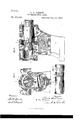
- Fig. 2 is a sectional view of the same, the plane of the section being indicated by line 2 2 in Fig. 1. In this View a portion of the shaft and a portion of the bushing are broken away.
- Fig. 3 is a detached side view of a portion of the shaft of the bearing, showing the roughened transverse groove formed therein.
- 4 designates a shaftturning in a bearing 5, which is horizontally divided and held together by suitable bolts 6.
- An oil-reservoir Z is suitably formed and arranged in a convenient place beneath the bearing, and an opening or passage-way 8 leads over the shaft transversely thereof from one side of the same to the other and communicates at each side with the said reservoir.
- This opening or passage-way 8 is out or formed in the bearing in such a way as to expose, preferably upon the top or crown of the shaft, a sufficient portion thereof for the oiling chain or belt 9 to come in contact with the shaft roughened zone or area 10, extending transversely around the same, and preferably sink the same into the shaft, so as to form a trans verse annular groove 11 therein.
- This roughening may be effected by forming longitudinal corrugations orteeth on the shaft, as shown in the drawings, though any preferred way of doing this may be adopted.
- the groove 11 receives the oil as it is raised by the chain, and the oil being thus deposited therein the groove acts as a storage-chamber for supplying the oil to the bearing.
- the oil is distributed longitudinally of the bearing by means of spiral ducts 12, formed in the working-face of the journal-box of the bearing, which box is preferably provided with a fixed bushing 13.
- spiral distributingducts 12 run in reverse directions over the working-face of the journal-box, so as to cross each other, as clearly shown in Fig. 2, and are obviously supplied by oil from the groove 11, the pressure of the oil in which will keep the ducts communicating therewith constantly o filled with oil.
- the lubricant or oil may be introduced into the reservoir in any suitable manner. For instance, it may be poured through the opening 17 at the top of the bearing, from where it would easily find its way through the 'pas sage-way 8 into the reservoir.
Landscapes
- Engineering & Computer Science (AREA)
- General Engineering & Computer Science (AREA)
- Chemical & Material Sciences (AREA)
- Combustion & Propulsion (AREA)
- Mechanical Engineering (AREA)
- Devices For Conveying Motion By Means Of Endless Flexible Members (AREA)
Description
0. A. PIERGIL AUTOMATIC LUBRIGATOR.
(No Model.)
311i! mlQ I r I WW I bawdy NITED STATES PATENT OFFICE.
CHARLES A. PIERCE, OF LYNN, MASSACHUSETTS, ASSIGNOR TO THE EUREKA ELECTRIC COMPANY, OF NEW YORK, N. Y.
AUTOMATIC LUBRICATO R.
SPECIFICATION forming part of Letters Patent NO. 450,421, dated April 14, 1891. Application filed January 13, 1891. Serial No. 377,631. (No model.)
To all whom, it may concern.-
. Be it known that I, CHARLES A. PIERCE, a citizen of the United States, residing at Lynn, Essex county, State of Massachusetts, have invented certain new and useful Improvements in Automatic Lubricators, of which the following is such a full, clear, and exact description as will enable any one skilled in the art to which it appertains to make and use the same, reference being had to the accompanying drawings, forming part of this specification.
My invention relates to the class of automatic lubricators in which an endless chain or belt is passed from an oil-reservoir over an exposed portion of the shaft of a bearing in such a manner as to automatically supply the oil to the bearing; and the invention consists in the various novel and peculiar combinations and arrangements of the several parts of the device, all as hereinafter fully described, and then pointed out in the claims.
In the accompanying drawings, illustrating my invention, Figure 1 is a sectional view of a bearing provided with my improvements,
the plane of the section being indicated by line 1 1 in Fig. 2. Fig. 2 is a sectional view of the same, the plane of the section being indicated by line 2 2 in Fig. 1. In this View a portion of the shaft and a portion of the bushing are broken away. Fig. 3 is a detached side view of a portion of the shaft of the bearing, showing the roughened transverse groove formed therein.
Referring to the said drawings, in which like numbers of reference indicate like parts throughout, 4 designates a shaftturning in a bearing 5, which is horizontally divided and held together by suitable bolts 6. An oil-reservoir Z is suitably formed and arranged in a convenient place beneath the bearing, and an opening or passage-way 8 leads over the shaft transversely thereof from one side of the same to the other and communicates at each side with the said reservoir. This opening or passage-way 8 is out or formed in the bearing in such a way as to expose, preferably upon the top or crown of the shaft, a sufficient portion thereof for the oiling chain or belt 9 to come in contact with the shaft roughened zone or area 10, extending transversely around the same, and preferably sink the same into the shaft, so as to form a trans verse annular groove 11 therein. This roughening may be effected by forming longitudinal corrugations orteeth on the shaft, as shown in the drawings, though any preferred way of doing this may be adopted. This roughening of the shaft where it makes contact with the oiling-chain will obviously increase the friction between the chain and shaft, so as to prevent the former from slipping on the same and to drive it with a positive and regular action, thereby keeping the supplyof the lubricant to the bearing uniform.
The groove 11 receives the oil as it is raised by the chain, and the oil being thus deposited therein the groove acts as a storage-chamber for supplying the oil to the bearing. The oil is distributed longitudinally of the bearing by means of spiral ducts 12, formed in the working-face of the journal-box of the bearing, which box is preferably provided with a fixed bushing 13. These spiral distributingducts 12 run in reverse directions over the working-face of the journal-box, so as to cross each other, as clearly shown in Fig. 2, and are obviously supplied by oil from the groove 11, the pressure of the oil in which will keep the ducts communicating therewith constantly o filled with oil. When the bearing is provided with the bushing 13, the same of course has to be cut away, as at 14, in order to expose the crown of the shaft to the oiling-chain 9, as will be readily understood from the draw- 5 ings. The hearing at each end is provided with an annular chamber 15, which communicates with a channel 16, running beneath the shaft and connecting the chamber 15 with the oil-reservoir 7, whereby the oil which has been I00 raised by the chain and distributed lengthwise the hearing may be returned to the reservoir.
By removing the upper portion of the horizontally-divided bearing 5 access may ready ily be had to the oiling-chain and the exposed portion of the shaft, as well as to the passage- 1 way 8, through which the chain travels.
The lubricant or oil may be introduced into the reservoir in any suitable manner. For instance, it may be poured through the opening 17 at the top of the bearing, from where it would easily find its way through the 'pas sage-way 8 into the reservoir.
Havm g thus described my improvements in automatic lubricators, what I claim as my in vention, and desire to secure by Letters Pating therefrom to the groove in the said shaft, and an 011mg chain or belt extending from the reservoir through the said openings and lying in a part of the groove in the shaft for automatically lubricating the bearing.
3. The combination, with a bearing, of a fixed bushing, a shaft formed with a roughened zone or area extending transversely around the shaft, an opening or passage-way leading over the shaft from one side thereof 7,5!) the other and communicating at each side with the oil reservoir, the said bushing cut away at the upper part thereof so as to expose the roughened portion of the said shaft to the said opening or passage-way, and an oiling chain or belt extending from the oil-reservoir through the opening and making contact with the exposed portion of the said shaft for antomatically lubricating the bearing.
*1. The combination, with a bearing, of a shaft 4, formed with a roughened zone or area 10, extending transversely therearound, an oil-reservoir 7, and a passage-way 8, leading over the shaft from one side thereof to the other and communicating with said oil-reservoir and exposing a portion of the shaft there in, and an endless oiling-chain 9, leading from the oil-reservoir through the passage-way 8 and making contact with the exposed portion of the shaft for automatically lubricating the bearing.
In testimony whereof I have hereunto set -my hand this 10th day of January, 1891, in the presence of the two subscribingwitnesses.
CHAS. A. PIERCE. Witnesses:
WILLIS FOWLER, CHAS. D. FOWLER.
Publications (1)
| Publication Number | Publication Date |
|---|---|
| US450421A true US450421A (en) | 1891-04-14 |
Family
ID=2519304
Family Applications (1)
| Application Number | Title | Priority Date | Filing Date |
|---|---|---|---|
| US450421D Expired - Lifetime US450421A (en) | Charles a |
Country Status (1)
| Country | Link |
|---|---|
| US (1) | US450421A (en) |
Cited By (1)
| Publication number | Priority date | Publication date | Assignee | Title |
|---|---|---|---|---|
| US20160289405A1 (en) * | 2013-11-19 | 2016-10-06 | Jx Nippon Oil & Energy Corporation | Prepreg, fibre-reinforced composite material, and particle-containing resin composition |
-
0
- US US450421D patent/US450421A/en not_active Expired - Lifetime
Cited By (1)
| Publication number | Priority date | Publication date | Assignee | Title |
|---|---|---|---|---|
| US20160289405A1 (en) * | 2013-11-19 | 2016-10-06 | Jx Nippon Oil & Energy Corporation | Prepreg, fibre-reinforced composite material, and particle-containing resin composition |
Similar Documents
| Publication | Publication Date | Title |
|---|---|---|
| US450421A (en) | Charles a | |
| US703838A (en) | Lubricator for loose pulleys. | |
| US974966A (en) | Means for lubricating bearings. | |
| US763409A (en) | Self-oiling loose-pulley hub and bushing. | |
| US466971A (en) | Lubricator for elevator-guides | |
| US779666A (en) | Belt-conveyer apparatus. | |
| US799020A (en) | Self-oiling bearing. | |
| US1304730A (en) | Lubricating device | |
| US447956A (en) | Lubricator | |
| US499186A (en) | George finfeock and geoege veesenmeyee | |
| US306975A (en) | thompson | |
| US435085A (en) | Automatic lubricator | |
| US373790A (en) | willcox | |
| US1121595A (en) | Lubricator. | |
| US809635A (en) | Car journal-box. | |
| US769432A (en) | Lubricated bearing. | |
| US310669A (en) | Loose-pulley lubricator | |
| US948192A (en) | Force-feed lubricator. | |
| US708324A (en) | Lubricating device. | |
| US262212A (en) | Device for lubricating loose wheels and pulleys | |
| US1648173A (en) | Lubricating system | |
| US746874A (en) | Lubricating device. | |
| US1349871A (en) | Lubricating device for dynamos and the like | |
| US694609A (en) | Holder for non-fluid lubricant. | |
| US728563A (en) | Automatic filtering-lubricator for the bushings of spinning-spindles. |