US4504104A - Unitary wiring device body - Google Patents
Unitary wiring device body Download PDFInfo
- Publication number
- US4504104A US4504104A US06/541,803 US54180383A US4504104A US 4504104 A US4504104 A US 4504104A US 54180383 A US54180383 A US 54180383A US 4504104 A US4504104 A US 4504104A
- Authority
- US
- United States
- Prior art keywords
- latch piece
- segment
- segments
- latching
- recess
- Prior art date
- Legal status (The legal status is an assumption and is not a legal conclusion. Google has not performed a legal analysis and makes no representation as to the accuracy of the status listed.)
- Expired - Fee Related
Links
- 230000013011 mating Effects 0.000 claims description 3
- 229920003023 plastic Polymers 0.000 abstract description 2
- 239000004033 plastic Substances 0.000 abstract description 2
- 102100022068 Serine palmitoyltransferase 1 Human genes 0.000 description 4
- 101710122478 Serine palmitoyltransferase 1 Proteins 0.000 description 4
- 102100022059 Serine palmitoyltransferase 2 Human genes 0.000 description 4
- 101710122477 Serine palmitoyltransferase 2 Proteins 0.000 description 4
- 238000009413 insulation Methods 0.000 description 4
- RYGMFSIKBFXOCR-UHFFFAOYSA-N Copper Chemical compound [Cu] RYGMFSIKBFXOCR-UHFFFAOYSA-N 0.000 description 1
- 239000004743 Polypropylene Substances 0.000 description 1
- 238000010276 construction Methods 0.000 description 1
- 229910052802 copper Inorganic materials 0.000 description 1
- 239000010949 copper Substances 0.000 description 1
- 229920002457 flexible plastic Polymers 0.000 description 1
- 239000002184 metal Substances 0.000 description 1
- 229910052751 metal Inorganic materials 0.000 description 1
- 238000012986 modification Methods 0.000 description 1
- 230000004048 modification Effects 0.000 description 1
- -1 polypropylene Polymers 0.000 description 1
- 229920001155 polypropylene Polymers 0.000 description 1
Images

Classifications
-
- H—ELECTRICITY
- H01—ELECTRIC ELEMENTS
- H01R—ELECTRICALLY-CONDUCTIVE CONNECTIONS; STRUCTURAL ASSOCIATIONS OF A PLURALITY OF MUTUALLY-INSULATED ELECTRICAL CONNECTING ELEMENTS; COUPLING DEVICES; CURRENT COLLECTORS
- H01R24/00—Two-part coupling devices, or either of their cooperating parts, characterised by their overall structure
- H01R24/28—Coupling parts carrying pins, blades or analogous contacts and secured only to wire or cable
-
- H—ELECTRICITY
- H01—ELECTRIC ELEMENTS
- H01R—ELECTRICALLY-CONDUCTIVE CONNECTIONS; STRUCTURAL ASSOCIATIONS OF A PLURALITY OF MUTUALLY-INSULATED ELECTRICAL CONNECTING ELEMENTS; COUPLING DEVICES; CURRENT COLLECTORS
- H01R13/00—Details of coupling devices of the kinds covered by groups H01R12/70 or H01R24/00 - H01R33/00
- H01R13/46—Bases; Cases
- H01R13/502—Bases; Cases composed of different pieces
- H01R13/506—Bases; Cases composed of different pieces assembled by snap action of the parts
-
- H—ELECTRICITY
- H01—ELECTRIC ELEMENTS
- H01R—ELECTRICALLY-CONDUCTIVE CONNECTIONS; STRUCTURAL ASSOCIATIONS OF A PLURALITY OF MUTUALLY-INSULATED ELECTRICAL CONNECTING ELEMENTS; COUPLING DEVICES; CURRENT COLLECTORS
- H01R13/00—Details of coupling devices of the kinds covered by groups H01R12/70 or H01R24/00 - H01R33/00
- H01R13/58—Means for relieving strain on wire connection, e.g. cord grip, for avoiding loosening of connections between wires and terminals within a coupling device terminating a cable
-
- H—ELECTRICITY
- H01—ELECTRIC ELEMENTS
- H01R—ELECTRICALLY-CONDUCTIVE CONNECTIONS; STRUCTURAL ASSOCIATIONS OF A PLURALITY OF MUTUALLY-INSULATED ELECTRICAL CONNECTING ELEMENTS; COUPLING DEVICES; CURRENT COLLECTORS
- H01R2103/00—Two poles
-
- H—ELECTRICITY
- H01—ELECTRIC ELEMENTS
- H01R—ELECTRICALLY-CONDUCTIVE CONNECTIONS; STRUCTURAL ASSOCIATIONS OF A PLURALITY OF MUTUALLY-INSULATED ELECTRICAL CONNECTING ELEMENTS; COUPLING DEVICES; CURRENT COLLECTORS
- H01R4/00—Electrically-conductive connections between two or more conductive members in direct contact, i.e. touching one another; Means for effecting or maintaining such contact; Electrically-conductive connections having two or more spaced connecting locations for conductors and using contact members penetrating insulation
- H01R4/02—Soldered or welded connections
-
- H—ELECTRICITY
- H01—ELECTRIC ELEMENTS
- H01R—ELECTRICALLY-CONDUCTIVE CONNECTIONS; STRUCTURAL ASSOCIATIONS OF A PLURALITY OF MUTUALLY-INSULATED ELECTRICAL CONNECTING ELEMENTS; COUPLING DEVICES; CURRENT COLLECTORS
- H01R4/00—Electrically-conductive connections between two or more conductive members in direct contact, i.e. touching one another; Means for effecting or maintaining such contact; Electrically-conductive connections having two or more spaced connecting locations for conductors and using contact members penetrating insulation
- H01R4/24—Connections using contact members penetrating or cutting insulation or cable strands
Definitions
- This invention pertains to wiring devices and, more particularly, is concerned with wiring devices such as plugs and receptacles for terminating electrical cords.
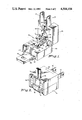
- FIG. 1 shows in an open position a wiring device embodying the invention
- FIG. 2 shows the device of FIG. 1 in a closed position
- FIG. 3 illustrates in more detail the strain relief feature of the wiring device
- FIG. 4 shows in more detail the channel and post arrangement of the wiring device.
- FIG. 1 shows a wiring device 10 which embodies the invention.
- the device shown is a male plug for terminating one end of a cord set; however, with minor design changes the device could be manufactured as a female receptacle.
- the device has only three pieces which are a body 11 and two electrical contacts 12, 13.
- the contacts 12, 13 may be blades if the device is a plug and female contacts if the device is a receptacle.
- Body 11 is molded in one piece of a flexible plastic such as polypropylene.
- the body has a first segment 14 and a second segment 15 joined by a web 16 of thin plastic, known as a living hinge.
- FIG. 1 the device 10 is shown in an open position prior to receiving an electric cord.
- a first living hinge 16 allows the two segments to pivot together as a book would close.
- Mating members of mechanical hinge 18, 19 are provided on each end of the first living hinge 16 so that if the first living hinge fails the two segments 14, 15 will remain latched together when in closed position.
- the segments 14, 15 may be latched in a closed position by a latch piece 20 which is attached to a second living hinge 21 on the first segment 14. Prongs 22 on second segment 15 engage a hole 33 in latch piece 20 when the device is closed. The end of latch piece 20 nearest hinge 21 is wider than the end nearest hole 33. The first segment 14 has a corresponding recess 34 to accept the latch piece 20. When the segments are closed the latch piece 20 forms an interlocking joint with the first segment 14 so that even if the second living hinge 21 fails the segments will remain latched in a closed position. Both latch piece 20 and recess 34 may be T-shaped.
- Prongs 22 are L-shaped, having distal ends received in a recessed extension of the hole in latch piece 20. In these circumstances, the prongs are flush with the latch piece, and the latch piece, in its latching position, is flush with the surfaces of the latchingly engaged ends of the segments (FIGS. 2 and 3).
- the second segment 15 has a rectangular entry hole 23 for accepting the end of an electric cord and a flexible finger 24 located adjacent to the entry hole 23.
- the first segment 14 is recessed to accept the cord.
- first segment 14 has a serrated corner 25 which leads the cord into a Y-shaped channel 26.
- serrated corner 25 which leads the cord into a Y-shaped channel 26.
- the segments 14, 15 are closed the serrated corner is opposite the entry hole 23.
- the cord 27 bends around the corner into the channel 26.
- the tip of the flexible finger 24 is in contact with the cord 27, and if the cord is pulled, the flexible finger 24 urges the cord 27 against the serrated corner 25 locking the cord in place and providing strain relief.
- channel 26 branches in two narrower channels 28, 29 which are separated by a divider 30.
- the cord is to be split into two wires which are laid in the separate channels 28, 29. This arrangement prevents short circuits which might otherwise occur if there are frayed wire strands.
- the bottom of the channels are beveled so that the wires self-center within their corresponding channel.
- At least one pair of flexible posts 31 are provided for each narrow channel.
- the posts 31 of each pair are arranged on opposite sides of the narrow channel to grip the wire and hold it in the corresponding narrow channel during assembly.
- the device will accept different size braidless parallel cord such as that which meets U.L. specification SPT-1 and SPT-2. Both types call for 18 gauge wire. SPT-1 uses 30 mil thick insulation and separates the wires by 3/64 inch, whereas SPT-2 uses 45 mil thick insulation and separates the wires by 5/64 inch.
- Electrical contacts 12, 13 are made of copper or other metal and are carried by the second segment 15.
- the contacts have points 32 arranged to pierce the insulation of the wire when the segments are closed.
- Each contact may have two or more points which are slightly offset so as to straddle the center of the wire preventing the wire from turning.
- the contacts may be blades or they may be female contacts with corresponding changes to the body.
- the described wiring device accepts both SPT-1 and SPT-2 standard wire. Only three pieces are used in its construction and is unitary so far as the consumer is concerned.
Landscapes
- Details Of Connecting Devices For Male And Female Coupling (AREA)
Abstract
Description
Claims (5)
Priority Applications (2)
| Application Number | Priority Date | Filing Date | Title |
|---|---|---|---|
| US06/541,803 US4504104A (en) | 1983-10-18 | 1983-10-18 | Unitary wiring device body |
| CA000465662A CA1235764A (en) | 1983-10-18 | 1984-10-17 | Unitary wiring device body |
Applications Claiming Priority (1)
| Application Number | Priority Date | Filing Date | Title |
|---|---|---|---|
| US06/541,803 US4504104A (en) | 1983-10-18 | 1983-10-18 | Unitary wiring device body |
Publications (1)
| Publication Number | Publication Date |
|---|---|
| US4504104A true US4504104A (en) | 1985-03-12 |
Family
ID=24161117
Family Applications (1)
| Application Number | Title | Priority Date | Filing Date |
|---|---|---|---|
| US06/541,803 Expired - Fee Related US4504104A (en) | 1983-10-18 | 1983-10-18 | Unitary wiring device body |
Country Status (2)
| Country | Link |
|---|---|
| US (1) | US4504104A (en) |
| CA (1) | CA1235764A (en) |
Cited By (4)
| Publication number | Priority date | Publication date | Assignee | Title |
|---|---|---|---|---|
| US4749367A (en) * | 1987-05-22 | 1988-06-07 | Fraser Ward M | Vulcan tap |
| US5295857A (en) * | 1992-12-23 | 1994-03-22 | Toly Elde V | Electrical connector with improved wire termination system |
| WO1997006580A1 (en) * | 1995-08-04 | 1997-02-20 | Phoenix Contact Gmbh & Co. | Cable connector |
| WO1997031408A1 (en) * | 1996-02-26 | 1997-08-28 | Koontat Development Company Ltd. | Pivoting electrical plug |
Citations (9)
| Publication number | Priority date | Publication date | Assignee | Title |
|---|---|---|---|---|
| US2590886A (en) * | 1948-04-08 | 1952-04-01 | Pedersen Svend Laessphie | Strain relief for electrical connectors |
| US2673968A (en) * | 1949-11-25 | 1954-03-30 | Leviton Mfg Company | Self-piercing electrical connector plug |
| US3409858A (en) * | 1966-08-29 | 1968-11-05 | Molex Products Co | Electrical connector having resilient arcuately bendable locking means |
| US3784961A (en) * | 1972-04-24 | 1974-01-08 | Hubbell Inc Harvey | Cable clamp |
| US3816819A (en) * | 1972-10-30 | 1974-06-11 | Gen Electric | Wire connector with wire locating device |
| US4010999A (en) * | 1975-09-02 | 1977-03-08 | Harvey Hubbell Incorporated | Dead-front electrical plug |
| US4072391A (en) * | 1976-08-13 | 1978-02-07 | Hung Jui Jung | Electric plug formed by squeezing assembly |
| US4138185A (en) * | 1977-10-04 | 1979-02-06 | Harvey Hubbell, Incorporated | Electric cord clamp device |
| US4145103A (en) * | 1978-06-01 | 1979-03-20 | Litton Systems, Inc. | Connector with low profile latch |
-
1983
- 1983-10-18 US US06/541,803 patent/US4504104A/en not_active Expired - Fee Related
-
1984
- 1984-10-17 CA CA000465662A patent/CA1235764A/en not_active Expired
Patent Citations (10)
| Publication number | Priority date | Publication date | Assignee | Title |
|---|---|---|---|---|
| US2590886A (en) * | 1948-04-08 | 1952-04-01 | Pedersen Svend Laessphie | Strain relief for electrical connectors |
| US2673968A (en) * | 1949-11-25 | 1954-03-30 | Leviton Mfg Company | Self-piercing electrical connector plug |
| US3409858A (en) * | 1966-08-29 | 1968-11-05 | Molex Products Co | Electrical connector having resilient arcuately bendable locking means |
| US3784961A (en) * | 1972-04-24 | 1974-01-08 | Hubbell Inc Harvey | Cable clamp |
| US3816819A (en) * | 1972-10-30 | 1974-06-11 | Gen Electric | Wire connector with wire locating device |
| US4010999A (en) * | 1975-09-02 | 1977-03-08 | Harvey Hubbell Incorporated | Dead-front electrical plug |
| US4072391A (en) * | 1976-08-13 | 1978-02-07 | Hung Jui Jung | Electric plug formed by squeezing assembly |
| US4155617A (en) * | 1976-08-13 | 1979-05-22 | Hung Jui Jung | Electric plugs |
| US4138185A (en) * | 1977-10-04 | 1979-02-06 | Harvey Hubbell, Incorporated | Electric cord clamp device |
| US4145103A (en) * | 1978-06-01 | 1979-03-20 | Litton Systems, Inc. | Connector with low profile latch |
Cited By (7)
| Publication number | Priority date | Publication date | Assignee | Title |
|---|---|---|---|---|
| US4749367A (en) * | 1987-05-22 | 1988-06-07 | Fraser Ward M | Vulcan tap |
| US5295857A (en) * | 1992-12-23 | 1994-03-22 | Toly Elde V | Electrical connector with improved wire termination system |
| WO1997006580A1 (en) * | 1995-08-04 | 1997-02-20 | Phoenix Contact Gmbh & Co. | Cable connector |
| JP3102892B2 (en) | 1995-08-04 | 2000-10-23 | フェニックス コンタクト ゲゼルシャフト ミット ベシュレンクテル ハフツング ウント コンパニー | Cable connection element |
| WO1997031408A1 (en) * | 1996-02-26 | 1997-08-28 | Koontat Development Company Ltd. | Pivoting electrical plug |
| US5772447A (en) * | 1996-02-26 | 1998-06-30 | Koontat Development Co. Ltd. | Pivoting electrical plug |
| AU708523B2 (en) * | 1996-02-26 | 1999-08-05 | Koontat Development Company Ltd | Pivoting electrical plug |
Also Published As
| Publication number | Publication date |
|---|---|
| CA1235764A (en) | 1988-04-26 |
Similar Documents
| Publication | Publication Date | Title |
|---|---|---|
| US4493523A (en) | Adaptive strain relief for wiring devices | |
| US5890924A (en) | Insulation-displacement-contact connector | |
| CA2176446C (en) | Electrical cord clamp | |
| EP0001159B1 (en) | Electrical connector | |
| US5033976A (en) | Hinged electrical connector | |
| KR910008530B1 (en) | Electrical connector | |
| US4449767A (en) | Connector assembly having improved keying and latching system | |
| US5820402A (en) | Electrical terminal constructed to engage stacked conductors in an insulation displacement manner | |
| US6116954A (en) | Electrical connector for making contact with at least one flat foil conductor | |
| US10559907B1 (en) | Electrical plug connector | |
| US4418978A (en) | Fuse plug | |
| US6126478A (en) | Wiring device with gripping of individual conductors | |
| US4089579A (en) | Ribbon connector constructions | |
| US5588870A (en) | Electrical cord clamp | |
| US4076364A (en) | Wiring device | |
| CA1211179A (en) | Electrical receptacle | |
| US6729895B1 (en) | Electrical connector | |
| US4504104A (en) | Unitary wiring device body | |
| JPH07335305A (en) | Electrical connector and its housing | |
| US6186821B1 (en) | Hermaphroditic cable connector | |
| US4420204A (en) | Dead-front electrical wiring device attachable to a power cord | |
| US5263878A (en) | Speedy connecting socket | |
| US4202590A (en) | Interlock arrangement for an electrical terminal enclosure | |
| US4753605A (en) | Electrical connector | |
| JP2622894B2 (en) | Wire branch forming tool |
Legal Events
| Date | Code | Title | Description |
|---|---|---|---|
| AS | Assignment |
Owner name: GTE PRODUCTS CORPORATION A DE CORP Free format text: ASSIGNMENT OF ASSIGNORS INTEREST.;ASSIGNORS:LEONG, HENRY;FIUMEFREDDO, JOHN;REEL/FRAME:004185/0831 Effective date: 19831012 |
|
| AS | Assignment |
Owner name: CHALLENGER CIRCLE F, INC., 720 MONMOUTH ST., TRENT Free format text: ASSIGNMENT OF ASSIGNORS INTEREST. SUBJECT TO CONDITIONS RECITED;ASSIGNOR:GTE PRODUCTS CORPORATION;REEL/FRAME:004195/0652 Effective date: 19831130 Owner name: CHALLENGER CIRCLE F, INC., NEW JERSEY Free format text: ASSIGNMENT OF ASSIGNORS INTEREST;ASSIGNOR:GTE PRODUCTS CORPORATION;REEL/FRAME:004195/0652 Effective date: 19831130 |
|
| FEPP | Fee payment procedure |
Free format text: PAYOR NUMBER ASSIGNED (ORIGINAL EVENT CODE: ASPN); ENTITY STATUS OF PATENT OWNER: LARGE ENTITY |
|
| REMI | Maintenance fee reminder mailed | ||
| FPAY | Fee payment |
Year of fee payment: 4 |
|
| SULP | Surcharge for late payment | ||
| AS | Assignment |
Owner name: CFC CAPITAL CORPORATION Free format text: SECURITY INTEREST;ASSIGNOR:LIBERTY LIGHTING CO., INC.,;REEL/FRAME:005228/0076 Effective date: 19890705 |
|
| AS | Assignment |
Owner name: LIBERTY LIGHTING CO., INC., A CORP. OF IL, NEW JER Free format text: ASSIGNMENT OF ASSIGNORS INTEREST.;ASSIGNOR:CHALLENGER CIRCLE F, INC.;REEL/FRAME:005221/0986 Effective date: 19890705 |
|
| REMI | Maintenance fee reminder mailed | ||
| LAPS | Lapse for failure to pay maintenance fees | ||
| FP | Lapsed due to failure to pay maintenance fee |
Effective date: 19970312 |
|
| STCH | Information on status: patent discontinuation |
Free format text: PATENT EXPIRED DUE TO NONPAYMENT OF MAINTENANCE FEES UNDER 37 CFR 1.362 |