US4498831A - Article stacking apparatus - Google Patents
Article stacking apparatus Download PDFInfo
- Publication number
- US4498831A US4498831A US06/489,227 US48922783A US4498831A US 4498831 A US4498831 A US 4498831A US 48922783 A US48922783 A US 48922783A US 4498831 A US4498831 A US 4498831A
- Authority
- US
- United States
- Prior art keywords
- plate
- elevator
- movement
- articles
- layer
- Prior art date
- Legal status (The legal status is an assumption and is not a legal conclusion. Google has not performed a legal analysis and makes no representation as to the accuracy of the status listed.)
- Expired - Fee Related
Links
- 238000013459 approach Methods 0.000 claims description 11
- 238000000034 method Methods 0.000 claims description 4
- 238000006073 displacement reaction Methods 0.000 claims 3
- 230000003028 elevating effect Effects 0.000 description 7
- 238000010586 diagram Methods 0.000 description 5
- 230000000994 depressogenic effect Effects 0.000 description 2
- 230000006835 compression Effects 0.000 description 1
- 238000007906 compression Methods 0.000 description 1
- 238000010276 construction Methods 0.000 description 1
- 230000001419 dependent effect Effects 0.000 description 1
- 230000000977 initiatory effect Effects 0.000 description 1
- 230000002441 reversible effect Effects 0.000 description 1
Images


Classifications
-
- B—PERFORMING OPERATIONS; TRANSPORTING
- B65—CONVEYING; PACKING; STORING; HANDLING THIN OR FILAMENTARY MATERIAL
- B65G—TRANSPORT OR STORAGE DEVICES, e.g. CONVEYORS FOR LOADING OR TIPPING, SHOP CONVEYOR SYSTEMS OR PNEUMATIC TUBE CONVEYORS
- B65G57/00—Stacking of articles
- B65G57/02—Stacking of articles by adding to the top of the stack
- B65G57/03—Stacking of articles by adding to the top of the stack from above
- B65G57/06—Gates for releasing articles
-
- Y—GENERAL TAGGING OF NEW TECHNOLOGICAL DEVELOPMENTS; GENERAL TAGGING OF CROSS-SECTIONAL TECHNOLOGIES SPANNING OVER SEVERAL SECTIONS OF THE IPC; TECHNICAL SUBJECTS COVERED BY FORMER USPC CROSS-REFERENCE ART COLLECTIONS [XRACs] AND DIGESTS
- Y10—TECHNICAL SUBJECTS COVERED BY FORMER USPC
- Y10S—TECHNICAL SUBJECTS COVERED BY FORMER USPC CROSS-REFERENCE ART COLLECTIONS [XRACs] AND DIGESTS
- Y10S414/00—Material or article handling
- Y10S414/10—Associated with forming or dispersing groups of intersupporting articles, e.g. stacking patterns
- Y10S414/11—Bricks
Definitions
- the present invention is directed to improvements in article handling apparatus employed to assemble a multilayer stack of articles in which the layers of the stack are made up of several individual articles arranged in a generally rectangular pattern.
- Davies et al U.S. Pat. No. 3,294,257 is a prior art patent disclosing a machine of the type with which the present invention is concerned, namely one in which a layer of articles is formed on a transfer plate, after which the plate is elevated to the necessary height and advanced into overlying relationship with the uppermost layer then in the stack being assembled. Upon subsequent retraction of the plate, the layer of articles is stripped from the plate and deposited upon the top of the stack.
- the present invention is especially directed to improvements over machines of the type disclosed in the above referred to U.S. Pat. No. 3,294,257; specifically in improvements relating to the structure of the elevating mechanism and gate employed in stripping the layers from the transfer plate, as well as improvements in the method of operation.
- a fixed frame includes a stacking table whose stack supporting surface may be defined by a plurality of conveyor rollers which, in the present invention, are not required to be power driven.
- An elevating frame is mounted upon the fixed frame for vertical movement.
- the elevating frame is of an open rectangular configuration having an opening slightly greater than twice as long as the stacking table and slightly wider than the stacking table so that one end of the elevating frame can be lowered past the stacking table with the elevating frame closely surrounding three sides of the rectangular stacking table.
- a transfer plate is slidably mounted upon the elevator frame for sliding movement longitudinally of the frame from one end to the other.
- the transfer plate When the elevator frame is in an elevated position relative to the stacking table, the transfer plate when at one end of the frame vertically overlies the entire stacking table. When the transfer plate is retracted to the opposite end of the elevator frame, the transfer plate is entirely clear of vertical alignment with the stacking table.
- a gate or stripper plate is mounted upon the elevator frame for movement between a retracted position in which the gate is located below the path of movement of the transfer plate, and an elevated position in which the gate is located slightly above the path of movement of the transfer plate.
- a layer of articles is formed upon the transfer plate with the plate retracted clear of the transfer table and the elevator frame at an elevation such that the transfer plate is substantially at the level of the stacking table.
- a control circuit is operated to elevate the plate a fixed distance to an elevation at which the path of movement of the plate is slightly above the surface of the stacking table.
- the plate is then driven forwardly at a relatively slow speed and during this relatively slow advance, the leading edge of the plate will engage a previously assembled stack located on the stacking table and push this previous stack clear of the stacking table as the first layer of the new stack is moved into position above the table.
- the gate is then actuated to its elevated position, and concurrently with the elevation of the gate to its stripping position, clamps mounted on opposite sides of the elevator frame may be moved into engagement with opposite sides of the layer of blocks supported upon the transfer plate to compact the layer transversely.
- the transfer plate is then retracted from beneath the layer of articles, the elevated gate engaging the layer of articles to strip them from the transfer plate as the plate is retracted.
- FIG. 1 is a schematic side elevational view of a stacking apparatus embodying the present invention, showing the elevator in an elevated position;
- FIG. 2 is a schematic top plan view of the machine with certain parts of the fixed frame omitted or indicated in broken line;
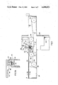
- FIG. 3 is an enlarged schematic cross-sectional view taken on the line 3--3 of FIG. 2;
- FIG. 3A is a further enlarged cross-sectional view taken on the line 3a-3a of FIG. 3;
- FIG. 4 is a schematic view taken approximately on the line 4--4 of FIG. 3 showing details of the gate construction
- FIG. 5 is a schematic top plan view of the forward end of the elevator frame showing a clamping assembly mounted thereon;
- FIG. 6 is a cross-sectional view taken on the line 6--6 of FIG. 5;
- FIG. 7A is a schematic line diagram of a portion of an electrical control circuit for the machine.
- FIG. 7B is a schematic line diagram illustrating another portion of the control circuit.
- FIG. 8 is a switch diagram helpful in understanding the operation of the control circuit.
- the major components of the machine include a fixed frame designated generally 20 and an elevating frame designated generally 22 which is shown at its maximum elevation in FIG. 1.
- a plurality of conveyor rollers 24 rotatably journaled in fixed frame 20 constitute a stacking table upon which articles are stacked during the operation of the machine.
- a pair of vertical posts 28 which constitute a portion of fixed frame 20 and project vertically upwardly at opposite sides of the machine. (See also FIG. 2) Fixedly mounted at the interior side of each of posts 28 is a vertically extending guide rail 30 whose opposite side edges are engaged by a series of rollers 32 rotatably mounted upon elevator frame 22 to guide the elevator frame in vertical movement relative to the fixed frame.
- Vertical movement of elevator frame 20 is accomplished by actuation of an elongate long stroke hydraulic motor 34 whose cylinder is fixedly mounted upon elevator frame 22 and whose piston rod 36 is fixedly secured to fixed frame 20.
- elevator frame 22 includes a pair of elongate longitudinally extending side frame members 38 which are rigidly connected at their opposite ends by a front cross frame member 40 and a rear cross frame member 42.
- the frame members 38, 40 and 42 when viewed from above as in FIG. 2 define an open rectangular frame which, with relationship to stacking table 26 shown in broken line in FIG. 2, is over twice as long and slightly wider than the rectangular stacking table 26.
- Elevator frame 22 is so located with respect to stacking table 26 that the frame can pass freely upwardly and downwardly past the stacking table with the table located adjacent the front (right) end of the elevator frame.
- a roller chain 46 is fixedly mounted in spaced underlying relationship to plate 44 as by a series of brackets 48 and pads 50 (shown only in FIG. 3A).
- the chains 46 are fixedly guided in sliding movement relative to elevator frame 22 by upper and lower rails 52, 54 (FIG. 3A) which are fixedly mounted on side frame members 38 of elevator frame 22.
- the transfer plate 44 can move in guided sliding movement longitudinally along frame 22 from the fully retracted position shown in FIGS. 2 and 3 to the opposite or forward end of frame 22, at which position the plate 44 would directly overlie stacking table 26.
- Drive motors 56 which preferably are reversible, variable speed motors, are employed to directly drive drive sprockets 58 (FIG. 3).
- An endless chain 60 is operatively trained around each drive sprocket 58 and an idler sprocket 62, the upper run of the chain being deflected downwardly by an idler sprocket 64 and the chain passing from sprocket 64 to a plate drive sprocket 66 which is meshed with the chain 46 attached to transfer plate 44. It is believed apparent that if sprocket 58 shown in FIG. 3 is driven by its motor 56 in a counter-clockwise direction as viewed in FIG.
- sprockets 66 and 64 will be driven in a clockwise direction to drive chain 46 to the right as viewed in FIG. 3. Opposite rotation of sprocket 58 will, of course, drive sprockets 66 and 64 in the opposite, chain return direction.
- transfer plate 44 extends transversely across the entire width of the opening in the rectangular frame defined by members 38, 40 and 42, the dimension of transfer plate 44 longitudinally of the rectangular frame is somewhat less than one-half of the length.
- plate 44 when plate 44 is in the fully retracted position shown in FIG. 3, its front edge F is at the indicated location.
- the rearward edge R of plate 44 is at the location indicated in broken line at R1 in FIG. 3.
- This arrangement provides a space through which a retractable gate or stripper plate designated generally 70 may be raised and lowered between the retracted position shown in FIG. 3 where the gate 70 is below the path of movement of transfer plate 44 and an elevated position in which the gate is elevated slightly above the path of movement of plate 44.
- Gate 70 is a movable assembly which includes a box beam 72 whose opposite ends are slidably guided in a pair of parallel vertically inclined guide rails 74 fixedly mounted on the outer side of each of side frame members 38 of elevator frame 22.
- Box frame member 72 carries a fixedly mounted plate 76 which is horizontally elongated and mounted in a general vertical plane upon box frame member 72.
- the gate is raised and lowered by a mechanism which includes a hydraulic motor designated generally 78 whose cylinder is fixedly mounted upon one elevator side frame member 38 and whose piston rod is coupled to one end of box beam 72.
- a chain and sprocket assembly is mounted within box beam 72.
- the chain and sprocket mechanism includes two pairs of sprockets 80, each pair consisting of two coaxially rotatable sprockets mounted in side-by-side relationship.
- a first length of chain 82 is fixed at its lower end to the guide rail assembly 74 and extends vertically along the guide rail assembly, its upper end being coupled to a spring tensioning mechanism designated generally 84.
- the chain 82 is in mesh with one of the two sprockets which constitute the right-hand pair (80a) of sprockets as viewed in FIG. 4.
- a second chain 86 is fixed at its lower end to the opposite guide rail assembly 74 and from this point is trained about a first of the left-hand pair of sprockets 80 as viewed in FIG. 3, then about that sprocket of the pair 80a which is not in mesh with vertical chain 82, thence back to the other of the left-hand pair of sprockets 80 and upwardly to have its upper end coupled to a spring tensioning mechanism designated generally 84.
- the crossed relationship of the chain 86 indicated in FIG. 4 maintains the opposite ends of beam 72 at the same level during movement of the beam.
- FIGS. 5 and 6 there is disclosed in these figures a clamping arrangement which may be considered an optional feature, but which is useful in most applications.
- the layer of articles is compacted in the longitudinal direction by the frictional forces exerted by the plate in withdrawing from beneath the articles which are held against longitudinal movement with the plate by the elevated gate.
- a fixed clamping plate 90 is mounted to extend parallel to the associated side frame member 38 over a length and at a position corresponding to that of the associated side of the stack as located on stacking table 26.
- the fixed plate 90 is mounted slightly above the path of movement of plate 44 and hence will be in horizontal alignment with a layer of articles supported on the plate.
- a movable clamp plate 92 is mounted in opposition to plate 90 and is capable of being driven in movement toward or away from fixed plate 90 by means of a hydraulic motor 94 whose piston rod is coupled to plate 92 and whose cylinder is mounted for movement about a horizontal pivot axis 96 upon a mounting bracket 98 fixedly mounted upon side frame member 38.
- a plurality of individual article engaging plates 100 are carried on the article facing side of movable plate 92 by sets of compression springs 102 so that the plates 100 can, as required, move independently of each other relative to plate 92.
- the articles which are being compacted between plates 90 and 92 may not all be of the exact same dimensions, that is, one transversely extending row of articles may be of a different length than the next adjacent row.
- the independent spring mounted plates 100 thus assure that all rows are compacted.
- a limit switch LS4 is mounted on the frame as shown in FIG. 6 with its striker engaged with the cylinder of hydraulic motor 94 which, as noted above, is hingedly mounted on the frame as by a hinge pin 96. When the motor 94 is in a horizontal position, the striker of limit switch LS4 is depressed.
- control of the operation of the various hydraulic and electric motors employed to drive the elevator, transfer plate and gates is by means of a series of solenoids SO1-SO10.
- the solenoids may be employed, in a well-known manner, to actuate four-way reversing valves connected in a well-known manner to the various motors to cause the motors to stroke in or out as the appropriate valve is actuated.
- the solenoids may be employed to establish various switching connections for appropriate operation of the motor.
- the heart of the electrical control circuit is represented by two rotary stepping switches SS1 and SS2 which, dependent upon the rotary position of the switch, open and close various load switch contacts designated S1, S2, etc. in accordance with the table of FIG. 8.
- Various timing and control relays are also employed and will be referred to below.
- stepping switch SS1 is employed to control the transfer of the first layer, while transfer of subsequent layers is controlled by stepping switch SS2.
- depression of the start button energizes a master control relay MCR which, immediately upon energization, locks itself in via contacts MCRa.
- a master control relay MCR which, immediately upon energization, locks itself in via contacts MCRa.
- the operator momentarily depresses the EJECT button to energize relay 1CR via normal closed contacts 2CRa and contacts 4CRa.
- Contacts 4CRa are closed at this time because the elevator frame is at its extreme lowered position and in this position holds closed the contacts of a limit switch LS1a which energizes relay 4CR.
- Limit switch LS1a is held closed by the elevator when the elevator is at its extreme lower position or within a very short distance of this position. LS1a is so arranged that it will open when the elevator has moved upwardly from its extreme lower position by a distance just sufficient to elevate the path of movement of the transfer plate to a location at which the plate will just clear the top of stacking table 26. When the elevator reaches this latter position, limit switch contacts LS1a open to deenergize relay 4CR and thus open contacts 4CRa.
- relay 1CR is locked in via its own contacts 1CRa which are closed when the relay is energized, and normally closed load switch contacts S17. Energization of relay 1CR also opens normally closed contacts 1CRb to prevent simultaneous energization of both relays 1CR and 2CR. Energization of relay 1CR also closes contacts 1CRc and 1CRd to thereby energize the stepping switch drive motor SS which promptly drives the stepping switch rotors R1 and R2 of the two stepping switches from their No. 20 position shown in the drawings to their No. 1 position.
- the transfer of the first layer of a stack is entirely under the control of stepping switch SS1.
- stepping switch SS1 When rotor R1 of stepping switch SS1 is advanced to its No. 1 position, the stepping switch, as seen from the load switch diagram of FIG. 8, closes load switch contacts S1.
- Plate 44 With the assembled layer supported on it then begins to move at a slow rate from its fully retracted position, and as it does so the front edge of the plate engages the lower layer of the previously assembled stack and pushes this stack from the stacking table as the plate carries the first layer of the next stack out over the table.
- the plate engages and closes a set of limit switch contacts LS2a which energize a timing relay 1TR.
- Closure of load switch contacts S4 energizes a second timing relay TR which, after a predetermined time delay sufficient for the gate to be fully actuated completes a circuit to the number 3 selector switch position of switch SS1 via contacts 2TRa to cause the rotors to advance to their respective positions 4.
- switch SS1 With switch SS1 in its number 4 position, contacts S3 remain closed, contacts S4 are opened and contacts S5 are closed. Closure of contacts S5 energizes relay SO7, which is the PLATE BACK FAST solenoid. Limit switch contacts LS3a, connected in series with solenoid SO7, are normally closed contacts which are opened by the plate as it approaches its fully retracted position. Energized simultaneously with solenoid SO7 is solenoid SO8, which is the PLATE BACK SLO solenoid which takes over upon opening contacts LS3a and drives the plate through the final approach to its fully retracted position at a slow rate.
- solenoid SO8 which is the PLATE BACK SLO solenoid which takes over upon opening contacts LS3a and drives the plate through the final approach to its fully retracted position at a slow rate.
- load switch contacts S3 and S6 are closed. Closure of load switch S6 energizes solenoid SO4, the ELEVATOR DOWN SLO solenoid, thus lowering the elevator slowly back toward its fully lowered position.
- load switch S3 has remained closed, thus maintaining the gate in its elevated position and the clamps at their clamping position in those cases where clamps are employed.
- contacts LS1a are again closed to energize relay 4CR, and thus contacts 4CRb to advance the stepping switch rotors to their number 6 position.
- load switch contacts 7 and 8 are closed (all others are open). Closure of load switch contacts S7 energizes solenoid SO10, the GATE DOWN solenoid.
- Closure of contacts S8 energizes still a further timing relay, 5TR which, after a predetermined time interval closes contacts 5TRa to advance the selector switch rotors to their respective number 7 positions. Energization of relay 5TRa also opens a set of normally closed contacts 5TRb after the predetermined time interval, thus deenergizing relay 1CR. Closure of contacts 5TRa, connected to stepping switch SS1, advances the stepping switch rotors to their respective number 7 positions, in which load switch contacts S8 are opened, deenergizing relay 5TR and restoring contacts 5TRb to their original normal closed positions.
- Both stepping switch rotors are in their respective number 7 positions, the elevator is in its lowered position, the transfer plate is in its fully retracted position and the gate is likewise in its retracted position.
- Sensing of light beam by the electric eye also closes a set of contacts PERb connected in series with position 7 of stepping switch SS2 to advance the rotor to position 8, at which position load switch S9 is opened while load switch S10 remains closed.
- the rotor remains at position 8 until relay 4TR times out, thereby closing contacts 4TRa to advance the rotor to position 9.
- Only load switch contacts S11 are closed, closure of these contacts energizing both the PLATE OUT FAST and PLATE OUT SLO solenoids. This causes the plate to be driven out fast into overlying relationship with the previously transferred layer until contacts LS2a are opened as the plate approaches its fully extended position.
- the PLATE OUT SLO solenoid SO6 takes over. Simultaneously with the opening of contacts LS2b, contacts LS2a are closed, energizing timing relay 1TR which after its preset interval of energization occurs closes contacts 1TRb to advance the rotors to their positions 10.
- load switch contacts S4 and S12 are closed, contact S4 energizing timing relay 2TR and contact S12 energizing the GATE UP solenoid. After time sufficient for the gate, and the clamps to reach their extended position, relay 2TR times out, closing contacts 2TRb connected to the number 10 position of stepping switch S2 to thereby advance the switch rotor to its number 11 position.
- load switch contacts 12 and 13 are closed--contacts S12 maintaining the GATE UP and contacts S13 energizing the plate BACK SLO and plate BACK FAST solenoids SO7 controls until the plate begins to approach its fully retracted position, at which time contacts LS3a are opened and solenoid SO8 takes over. Opening of contacts LS3a occurs simultaneously with the closure of contacts LS3b which actuates that timing relay 3TR to initiate a time closing of contacts 3TRb to advance the stepping switch rotor to its number 12 position.
- Subsequent layers may be stacked by initiating the cycle by pressing the CUBE button as described above.
Landscapes
- Engineering & Computer Science (AREA)
- Mechanical Engineering (AREA)
- Stacking Of Articles And Auxiliary Devices (AREA)
Abstract
Description
Claims (12)
Priority Applications (2)
| Application Number | Priority Date | Filing Date | Title |
|---|---|---|---|
| US06/489,227 US4498831A (en) | 1983-04-27 | 1983-04-27 | Article stacking apparatus |
| CA000448551A CA1208246A (en) | 1983-04-27 | 1984-02-29 | Article stacking apparatus |
Applications Claiming Priority (1)
| Application Number | Priority Date | Filing Date | Title |
|---|---|---|---|
| US06/489,227 US4498831A (en) | 1983-04-27 | 1983-04-27 | Article stacking apparatus |
Publications (1)
| Publication Number | Publication Date |
|---|---|
| US4498831A true US4498831A (en) | 1985-02-12 |
Family
ID=23942947
Family Applications (1)
| Application Number | Title | Priority Date | Filing Date |
|---|---|---|---|
| US06/489,227 Expired - Fee Related US4498831A (en) | 1983-04-27 | 1983-04-27 | Article stacking apparatus |
Country Status (2)
| Country | Link |
|---|---|
| US (1) | US4498831A (en) |
| CA (1) | CA1208246A (en) |
Cited By (2)
| Publication number | Priority date | Publication date | Assignee | Title |
|---|---|---|---|---|
| US4836731A (en) * | 1988-03-07 | 1989-06-06 | Builders Equipment Company | Method and apparatus for cubing stones of diverse geometries |
| US4941813A (en) * | 1988-12-13 | 1990-07-17 | Grubb Jr Lloyd T | Mold guidance system for block making machinery |
Citations (8)
| Publication number | Priority date | Publication date | Assignee | Title |
|---|---|---|---|---|
| US2981420A (en) * | 1957-07-09 | 1961-04-25 | Sven Leijonmarck | Piling machine for sheet-like materials |
| US3247981A (en) * | 1962-09-11 | 1966-04-26 | Certain Teed Prod Corp | Package arranging equipment |
| US3294257A (en) * | 1963-12-02 | 1966-12-27 | Columbia Machine | Package-handling apparatus |
| US3696945A (en) * | 1970-12-09 | 1972-10-10 | Besser Co | Block cubing apparatus |
| US3833132A (en) * | 1969-09-03 | 1974-09-03 | F Alduk | Pallet loading apparatus |
| US3901391A (en) * | 1973-02-07 | 1975-08-26 | Columbia Machine | Article positioning and stacking apparatus |
| US3941048A (en) * | 1974-07-19 | 1976-03-02 | Okura Yusoki Kabushiki Kaisha | Apparatus for loading goods on a pallet |
| US4018031A (en) * | 1972-05-19 | 1977-04-19 | Marcal Paper Mills, Inc. | Article packaging machine |
-
1983
- 1983-04-27 US US06/489,227 patent/US4498831A/en not_active Expired - Fee Related
-
1984
- 1984-02-29 CA CA000448551A patent/CA1208246A/en not_active Expired
Patent Citations (8)
| Publication number | Priority date | Publication date | Assignee | Title |
|---|---|---|---|---|
| US2981420A (en) * | 1957-07-09 | 1961-04-25 | Sven Leijonmarck | Piling machine for sheet-like materials |
| US3247981A (en) * | 1962-09-11 | 1966-04-26 | Certain Teed Prod Corp | Package arranging equipment |
| US3294257A (en) * | 1963-12-02 | 1966-12-27 | Columbia Machine | Package-handling apparatus |
| US3833132A (en) * | 1969-09-03 | 1974-09-03 | F Alduk | Pallet loading apparatus |
| US3696945A (en) * | 1970-12-09 | 1972-10-10 | Besser Co | Block cubing apparatus |
| US4018031A (en) * | 1972-05-19 | 1977-04-19 | Marcal Paper Mills, Inc. | Article packaging machine |
| US3901391A (en) * | 1973-02-07 | 1975-08-26 | Columbia Machine | Article positioning and stacking apparatus |
| US3941048A (en) * | 1974-07-19 | 1976-03-02 | Okura Yusoki Kabushiki Kaisha | Apparatus for loading goods on a pallet |
Cited By (2)
| Publication number | Priority date | Publication date | Assignee | Title |
|---|---|---|---|---|
| US4836731A (en) * | 1988-03-07 | 1989-06-06 | Builders Equipment Company | Method and apparatus for cubing stones of diverse geometries |
| US4941813A (en) * | 1988-12-13 | 1990-07-17 | Grubb Jr Lloyd T | Mold guidance system for block making machinery |
Also Published As
| Publication number | Publication date |
|---|---|
| CA1208246A (en) | 1986-07-22 |
Similar Documents
| Publication | Publication Date | Title |
|---|---|---|
| US3719288A (en) | Article handling apparatus | |
| US2228887A (en) | Stacker and unloader | |
| US4024965A (en) | Bag palletizing apparatus | |
| US4067456A (en) | Apparatus for arranging and stacking nonrigid articles | |
| US4436472A (en) | Sheet piling devices | |
| US3442400A (en) | Carton palletizing apparatus | |
| US4189270A (en) | Sheet transfer and stacking apparatus | |
| US4576536A (en) | Machine for stacking automatically packs of panels of different sizes on respective lifting platforms | |
| US2897949A (en) | Box-stacking mechanism | |
| GB1415104A (en) | Method and apparatus for packagiang baths of compressible materials | |
| US3111233A (en) | Pallet loading machine | |
| US5054994A (en) | Apparatus for stacking unfired brick | |
| US4099363A (en) | Apparatus for compressing and packaging articles | |
| US3754657A (en) | Filter presses | |
| GB1462128A (en) | Sheet stacking machine | |
| US2915202A (en) | Timber-stacking apparatus and the like | |
| US4498831A (en) | Article stacking apparatus | |
| US3850316A (en) | Apparatus for loading and unloading vertically stacked racks | |
| US2985322A (en) | Apparatus for handling rigid sheet material | |
| US2895624A (en) | Elevator for use in a lumber stacker | |
| US3531905A (en) | Process for forming packaging boxes and simultaneously packing articles therein and apparatus therefor | |
| CA1130830A (en) | Conveying and stacking machine | |
| DE4135727A1 (en) | Collecting together individual wooden elements from packets - by subjecting them to various stages of sepn. and gluing of edges and pressing together to form panels of parquet flooring | |
| US3640407A (en) | Apparatus for handling books | |
| US3387720A (en) | Stacking machine |
Legal Events
| Date | Code | Title | Description |
|---|---|---|---|
| AS | Assignment |
Owner name: BESSER INDUSTRIES, INC.; 106 GREEN ST., ROANOKE, I Free format text: ASSIGNMENT OF ASSIGNORS INTEREST.;ASSIGNOR:SALTS, THOMAS R.;REEL/FRAME:004123/0430 Effective date: 19830421 |
|
| FEPP | Fee payment procedure |
Free format text: PAYOR NUMBER ASSIGNED (ORIGINAL EVENT CODE: ASPN); ENTITY STATUS OF PATENT OWNER: SMALL ENTITY |
|
| FPAY | Fee payment |
Year of fee payment: 4 |
|
| REFU | Refund |
Free format text: REFUND OF EXCESS PAYMENTS PROCESSED (ORIGINAL EVENT CODE: R169); ENTITY STATUS OF PATENT OWNER: SMALL ENTITY |
|
| FPAY | Fee payment |
Year of fee payment: 8 |
|
| REMI | Maintenance fee reminder mailed | ||
| LAPS | Lapse for failure to pay maintenance fees | ||
| FP | Lapsed due to failure to pay maintenance fee |
Effective date: 19970212 |
|
| AS | Assignment |
Owner name: HARRIS TRUST AND SAVINGS BANK, AS AGENT, ILLINOIS Free format text: COLLATERAL AGREEMENT;ASSIGNOR:BESSER COMPANY;REEL/FRAME:013231/0474 Effective date: 20020725 |
|
| AS | Assignment |
Owner name: STANDARD FEDERAL BANK NATIONAL ASSOCIATION, MICHIG Free format text: SECURITY AGREEMENT;ASSIGNOR:BESSER COMPANY;REEL/FRAME:015603/0977 Effective date: 20041223 |
|
| AS | Assignment |
Owner name: BESSER COMPANY, MICHIGAN Free format text: RELEASE AND REASSIGNMENT OF PATENTS;ASSIGNOR:HARRIS TRUST AND SAVINGS BANK;REEL/FRAME:015612/0984 Effective date: 20041223 |
|
| STCH | Information on status: patent discontinuation |
Free format text: PATENT EXPIRED DUE TO NONPAYMENT OF MAINTENANCE FEES UNDER 37 CFR 1.362 |