US4494504A - Stratified burn internal combustion engine - Google Patents
Stratified burn internal combustion engine Download PDFInfo
- Publication number
- US4494504A US4494504A US06/386,611 US38661182A US4494504A US 4494504 A US4494504 A US 4494504A US 38661182 A US38661182 A US 38661182A US 4494504 A US4494504 A US 4494504A
- Authority
- US
- United States
- Prior art keywords
- intake
- intake valve
- internal combustion
- valve
- combustion engine
- Prior art date
- Legal status (The legal status is an assumption and is not a legal conclusion. Google has not performed a legal analysis and makes no representation as to the accuracy of the status listed.)
- Expired - Fee Related
Links
Images


Classifications
-
- F—MECHANICAL ENGINEERING; LIGHTING; HEATING; WEAPONS; BLASTING
- F02—COMBUSTION ENGINES; HOT-GAS OR COMBUSTION-PRODUCT ENGINE PLANTS
- F02B—INTERNAL-COMBUSTION PISTON ENGINES; COMBUSTION ENGINES IN GENERAL
- F02B17/00—Engines characterised by means for effecting stratification of charge in cylinders
-
- F—MECHANICAL ENGINEERING; LIGHTING; HEATING; WEAPONS; BLASTING
- F02—COMBUSTION ENGINES; HOT-GAS OR COMBUSTION-PRODUCT ENGINE PLANTS
- F02B—INTERNAL-COMBUSTION PISTON ENGINES; COMBUSTION ENGINES IN GENERAL
- F02B19/00—Engines characterised by precombustion chambers
- F02B19/12—Engines characterised by precombustion chambers with positive ignition
-
- F—MECHANICAL ENGINEERING; LIGHTING; HEATING; WEAPONS; BLASTING
- F02—COMBUSTION ENGINES; HOT-GAS OR COMBUSTION-PRODUCT ENGINE PLANTS
- F02B—INTERNAL-COMBUSTION PISTON ENGINES; COMBUSTION ENGINES IN GENERAL
- F02B23/00—Other engines characterised by special shape or construction of combustion chambers to improve operation
- F02B23/08—Other engines characterised by special shape or construction of combustion chambers to improve operation with positive ignition
-
- F—MECHANICAL ENGINEERING; LIGHTING; HEATING; WEAPONS; BLASTING
- F02—COMBUSTION ENGINES; HOT-GAS OR COMBUSTION-PRODUCT ENGINE PLANTS
- F02F—CYLINDERS, PISTONS OR CASINGS, FOR COMBUSTION ENGINES; ARRANGEMENTS OF SEALINGS IN COMBUSTION ENGINES
- F02F1/00—Cylinders; Cylinder heads
- F02F1/24—Cylinder heads
- F02F1/42—Shape or arrangement of intake or exhaust channels in cylinder heads
- F02F1/4214—Shape or arrangement of intake or exhaust channels in cylinder heads specially adapted for four or more valves per cylinder
-
- F—MECHANICAL ENGINEERING; LIGHTING; HEATING; WEAPONS; BLASTING
- F02—COMBUSTION ENGINES; HOT-GAS OR COMBUSTION-PRODUCT ENGINE PLANTS
- F02M—SUPPLYING COMBUSTION ENGINES IN GENERAL WITH COMBUSTIBLE MIXTURES OR CONSTITUENTS THEREOF
- F02M13/00—Arrangements of two or more separate carburettors; Carburettors using more than one fuel
- F02M13/02—Separate carburettors
- F02M13/023—Special construction of the control rods
-
- F—MECHANICAL ENGINEERING; LIGHTING; HEATING; WEAPONS; BLASTING
- F02—COMBUSTION ENGINES; HOT-GAS OR COMBUSTION-PRODUCT ENGINE PLANTS
- F02M—SUPPLYING COMBUSTION ENGINES IN GENERAL WITH COMBUSTIBLE MIXTURES OR CONSTITUENTS THEREOF
- F02M7/00—Carburettors with means for influencing, e.g. enriching or keeping constant, fuel/air ratio of charge under varying conditions
- F02M7/12—Other installations, with moving parts, for influencing fuel/air ratio, e.g. having valves
- F02M7/133—Auxiliary jets, i.e. operating only under certain conditions, e.g. full power
-
- F—MECHANICAL ENGINEERING; LIGHTING; HEATING; WEAPONS; BLASTING
- F02—COMBUSTION ENGINES; HOT-GAS OR COMBUSTION-PRODUCT ENGINE PLANTS
- F02B—INTERNAL-COMBUSTION PISTON ENGINES; COMBUSTION ENGINES IN GENERAL
- F02B1/00—Engines characterised by fuel-air mixture compression
- F02B1/02—Engines characterised by fuel-air mixture compression with positive ignition
- F02B1/04—Engines characterised by fuel-air mixture compression with positive ignition with fuel-air mixture admission into cylinder
-
- F—MECHANICAL ENGINEERING; LIGHTING; HEATING; WEAPONS; BLASTING
- F02—COMBUSTION ENGINES; HOT-GAS OR COMBUSTION-PRODUCT ENGINE PLANTS
- F02F—CYLINDERS, PISTONS OR CASINGS, FOR COMBUSTION ENGINES; ARRANGEMENTS OF SEALINGS IN COMBUSTION ENGINES
- F02F1/00—Cylinders; Cylinder heads
- F02F1/24—Cylinder heads
- F02F2001/244—Arrangement of valve stems in cylinder heads
- F02F2001/245—Arrangement of valve stems in cylinder heads the valve stems being orientated at an angle with the cylinder axis
-
- Y—GENERAL TAGGING OF NEW TECHNOLOGICAL DEVELOPMENTS; GENERAL TAGGING OF CROSS-SECTIONAL TECHNOLOGIES SPANNING OVER SEVERAL SECTIONS OF THE IPC; TECHNICAL SUBJECTS COVERED BY FORMER USPC CROSS-REFERENCE ART COLLECTIONS [XRACs] AND DIGESTS
- Y02—TECHNOLOGIES OR APPLICATIONS FOR MITIGATION OR ADAPTATION AGAINST CLIMATE CHANGE
- Y02T—CLIMATE CHANGE MITIGATION TECHNOLOGIES RELATED TO TRANSPORTATION
- Y02T10/00—Road transport of goods or passengers
- Y02T10/10—Internal combustion engine [ICE] based vehicles
- Y02T10/12—Improving ICE efficiencies
Definitions
- This invention relates to internal combustion spark ignition piston engines and is particularly directed to engines of this type in which a stratified burn takes place upon ignition of an enriched mixture by means of a spark plug.
- each intake stroke a relatively small amount of relatively rich mixture is introduced through a first intake valve port at relatively low speed into the combustion chamber.
- a relatively large amount of relatively lean mixture is introduced into the same combustion chamber through a second intake valve port at relatively high speed. This forms stable stratification of two different mixtures.
- the rich mixture remains in the vicinity of the first intake valve port and is ignited by a spark plug for reliable initiation of the burning. A strong flame thus produced then ignites the lean mixture in the remaining portion of the combustion chamber even though the lean mixture may be too lean to be reliably ignited directly from a spark plug.
- the total air-fuel ratio of the two mixtures may be leaner than the stoichiometric air-fuel ratio, and as a result it is possible to reduce the emission of CO and HC as well as to improve the indicated specific fuel consumption. Furthermore, the combustion takes place separately for rich mixture and lean mixture, thereby controlling generation of NO x .
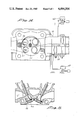
- FIG. 1 is a bottom view partly in section showing a preferred embodiment of this invention.
- FIG. 2 is a side elevation partly broken away showing a portion of FIG. 1.
- FIG. 3 is a graph showing the relationship of opening area percentages of the first and second throttle valves shown in FIG. 1.
- FIG. 4 is a graph showing the relationship of air weight percentage to the accelerator operating stroke.
- FIG. 5 is a bottom view similar to FIG. 1 showing a first modification.
- FIG. 6 is a side elevation showing a portion of FIG. 5.
- FIG. 7 is a fragmentary sectional plan view showing a second modification.
- FIG. 8 is a bottom plan view showing the position of an apertured cover for the spark plug electrode.
- FIG. 9 is a bottom plan view showing a modified form of combustion chamber.
- FIG. 10 is a sectional elevation of the device shown in FIG. 9.
- FIG. 11 is a diagram showing valve opening characteristics.
- FIG. 12 is a sectional detail showing the spark plug mounting.
- FIG. 13 is a diagram showing relationship of the air-fuel ratio to the accelerator operating stroke.
- FIG. 14 is a view similar to FIG. 1 showing another modification.
- FIG. 15 is a sectional side elevation of the device shown in FIG. 14.
- FIG. 16 is a graph showing valve opering characteristics of the device of FIGS. 14 and 15.
- FIG. 17 is a diagram showing operation of air valves.
- FIG. 18 is a sectional detail showing the spark plug cover as shown in FIG. 8.
- FIG. 19 is a side elevation of another embodiment of a carburetor shown in FIG. 1.
- FIG. 20 is a side elevation of another embodiment of a carburetor shown in FIG. 1.
- FIGS. 1 and 2 the preferred form of the invention shown in FIGS. 1 and 2 concerns an internal combustion spark ignition piston engine generally designated 10.
- the combustion chamber 11 is formed in the engine head at one end of a cylinder, not shown.
- a first intake valve 12 of conventional form controlling flow into the combustion chamber through a first intake valve port 13.
- a second intake valve 14 Adjacent the first intake valve 12 and on the same side of the combustion chamber 11 is a second intake valve 14 controlling flow into the combustion chamber 11 through a second intake valve port 15.
- An exhaust valve 16 on the other side of the combustion chamber 11 controls flow of exhaust gases through the exhaust valve port 17.
- a spark plug 18 has an electrode extending into the combustion chamber 11 and positioned near to the first intake valve 12.
- the first intake valve port 13 is connected through first intake passage 19 to a first mixture source 21 of a carburetor.
- a first throttle valve 22 controls flow of a rich air-fuel mixture through the first intake passage 19.
- the second intake valve port 15 is connected through a second intake passage 23 to a second mixture source 24. Flow of relatively lean mixture from the second mixture source through the second intake passage 23 is controlled by the second throttle valve 25.
- operations of the first throttle valve 22 and the second throttle valve 25 are controlled so that intake of air, at least in the range of low loads of the engine, is set as follows: First, the air weight G 1 introduced into the combustion chamber 11 through the first intake valve port 13 during the intake stroke of the engine is set to be smaller as compared with the air weight G 2 introduced into the combustion chamber 11 through the second intake valve port 15. Stated in another form:
- relatively rich mixture introduced through said first intake valve port 13 is controlled to be relatively small in amount, while lean mixture introduced through the second intake valve port 15 is controlled to be relatively large in amount.
- the controlling means may comprise a cam 26 fixed on the shaft 27 carrying the second throttle valve 25.
- a lever 28 fixed on the shaft 29 carrying the first throttle valve 22 is provided with a follower roller 31 which engages the outer surface of the cam 26.
- a throttle wire 32 is attached to a crank arm 33 fixed to the throttle shaft 27.
- the second throttle valve 25 is opened gradually by the throttle wire 32, the first throttle valve 22 also opens.
- FIG. 3 shows the variation percentages of the aforementioned G 1 and G 2 in such operations, the relation being G 1 ⁇ G 2 at low load to medium load.
- the means for controlling the relative air weight is not limited to the cam and follower construction shown in FIGS. 1 and 2, but may take another form such as that shown in FIGS. 5 and 6, for example.
- Fixed to the shaft 34 for the first throttle valve 35 is a wire drum 36.
- Fixed to the shaft 37 for the second throttle valve 38 is a wire drum 39. Cables 41 and 42 are secured to the wire drums 36 and 39, respectively, and are joined to a cross bar 43 fixed to one end of the throttle wire 44 which is connected with accelerator.
- the peripheral configuration of each drum 36 and 39 is chosen so as to regulate the opening movement of the first throttle valve 35 with respect to the opening movement of the second throttle valve 38.
- only one throttle shaft 45 is employed, and the first throttle valve 46 and the second throttle valve 47 are both mounted upon it.
- the bore diameter 48 for the first throttle valve 46 is made smaller than the bore diameter 49 for the second throttle valve 47 to cause lower flow rate past throttle valve 46 as compared to the flow rate past throttle valve 47.
- a TH .sbsb.1 /A V .sbsb.1 corresponds to the flow rate of rich mixture introduced through the first intake valve port 13
- a TH .sbsb.2 /A V .sbsb.2 corresponds to that for the second intake valve port 15. Accordingly, the flow rate of rich mixture introduced through the first intake valve port 13 is controlled to be relatively low, and the flow rate of lean mixture introduced through the second intake valve port 15 is relatively high.
- the engine as a whole operates as follows: During intake strokes of the engine, through the second intake valve port 15 lean mixture is supplied in large quantities and at high speed and is introduced into the lower portion of the combustion chamber 11. At the same time rich mixture is delivered in small quantities through the first intake valve port 13 and remains in the upper portion of the combustion chamber 11. Accordingly, the rich mixture does not diffuse throughout the combustion chamber 11 but remains in the upper portion and in the vicinity of the first intake valve port 13 near the spark plug 18, while the lower portion of the combustion chamber 11 is occupied by the relatively lean mixture. During the subsequent compression and expansion strokes of the engine the rich mixture is ignited by the spark plug 18, its flame propagating successively into the lean mixture below to burn it, accomplishing stratified combustion.
- the spark plug 18 is positioned so that its electrode is exposed in the combuston chamber 11, as shown in FIG. 1, or as shown in FIGS. 8 and 18, is covered by a shell or enclosure 51 having apertures 52 communicating with the combustion chamber 11.
- the first intake valve port 53 may be relatively large in diameter.
- the maximum lift H 1 of the first intake valve 12 is larger as compared to the maximum lift H 2 of the second intake valve 14, whereby it is possible to introduce large quantities of rich mixture particularly in the high load range, enabling the engine power output to be increased.
- timing for the opening of the first intake valve 12 and the timing for the opening of the second intake valve 14 are indicated in FIG. 11 by the lines In 1 and In 2 , respectively. It is preferred that the first intake valve 12 opens after the second intake valve 14 opens, which acts to reduce somewhat the introduction of such mixture. In this case, the first intake valve 12 starts to open before top dead center.
- Rich mixture obtained from the first mixture source 21 generally has an air-fuel ratio of not less than 7
- the lean mixture obtained from the second mixture source 24 generally has an air-fuel ratio of not more than 30.
- one or the other of the mixture sources may be constructed as shown in FIG. 20 and FIG. 19, for instance, and may be of the type that regulates the air-fuel ratios in proportion to the increase of air flow as shown by G 1 and G 2 in FIG. 13, for example.
- the combustion chamber 11 may be of the type having a cavity 55 in the upper portion thereof, with the first intake valve port 53 and the electrode of the spark plug 18 inside the cavity 55.
- the maximum lift H 1 of the first intake valve 12 be greater than the depth D of the cavity 55.
- H 1 >D When the valve 12a is open, it tends to cover the mouth of the cavity 55 to minimize diffusion of the rich mixture in the cavity 55.
- the electrode of the spark plug 18 may be located in proximity to the boundary line between the cavity 55 and the combustion chamber 11, as shown in FIG. 12, for better cooling of the spark plug electrode.
- two exhaust valve ports 56 and 57 are provided, closed by exhaust valves 16a and 16b, the former being placed inside the cavity 55.
- the opening characteristics of the intake and the exhaust valve inside the cavity 55 are as shown in FIG. 16 by In 1 and Ex 1 , for instance, and it is preferred that the overlap ⁇ 1 of the former and the overlap ⁇ 2 of the latter have the relationship ⁇ 1 ⁇ 2 .
- each characteristic curve or lift curve is symmetrical with respect to the top dead center, as shown in the same figure.
- the absorber 59 is connected through valve 60 and conduit 61 to the second intake port 15.
- a first air valve 62 and a second air valve 63 operate at a minus load of the engine and act to supply small quantities of air to the first intake passage 19 and large quantities of air to the second intake passage 23.
- the duration of each opening of the first air valve 62 is shorter as compared with that of the second air valve 63.
- the engine 10 may be of the exhaust gas recirculation type, as shown in FIG. 1, in which the exhaust passageway 64 extends from the exhaust passage 17 through the First intake passage 19.
- a control valve 65 is positioned in the passageway 64.
- FIG. 19 illustrates a pneumatic type carburetor.
- the diaphragm 70 moves upwardly upon vacuum increase in the intake passage 19. This movement of diaphragm 70 results in making the air-fuel mixture lean by closing the path 72 in the main jet.
- FIG. 20 illustrates a pneumatic type carburetor which acts in the opposite manner to the one shown in FIG. 19. In the embodiment shown in FIG. 20 diaphragm 70 moves downwardly upon vacuum increase in the intake passage 23. This movement of the diaphragm 70 results in making the air-fuel mixture richer by opening the path 72 in the main jet.
- introduction of rich mixture into the combustion chamber may be accomplished in relatively small quantities and at low speed, and to have the rich mixture retained in a particular portion of the combustion chamber to prevent it from diffusing, so that a stable stratified combustion is accomplished.
- the pollutants HC, CO and NO x in the exhaust emissions are reduced, and the indicated specific fuel consumption is improved.
Landscapes
- Engineering & Computer Science (AREA)
- Chemical & Material Sciences (AREA)
- Combustion & Propulsion (AREA)
- Mechanical Engineering (AREA)
- General Engineering & Computer Science (AREA)
- Combustion Methods Of Internal-Combustion Engines (AREA)
- Valve-Gear Or Valve Arrangements (AREA)
Abstract
Description
G.sub.1 <G.sub.2
A.sub.V.sbsb.1 /A.sub.V.sbsb.2 ≈Ap.sub.1 /Ap.sub.2
Claims (18)
A.sub.TH.sbsb.1 /A.sub.V.sbsb.1 <A.sub.TH.sbsb.2 /A.sub.V.sbsb.2
A.sub.V.sbsb.1 >A.sub.V.sbsb.2
Applications Claiming Priority (2)
| Application Number | Priority Date | Filing Date | Title |
|---|---|---|---|
| JP13727478A JPS5564115A (en) | 1978-11-09 | 1978-11-09 | Internal combustion engine |
| JP53-137274 | 1978-11-09 |
Related Parent Applications (1)
| Application Number | Title | Priority Date | Filing Date |
|---|---|---|---|
| US06091874 Continuation | 1979-11-07 |
Publications (1)
| Publication Number | Publication Date |
|---|---|
| US4494504A true US4494504A (en) | 1985-01-22 |
Family
ID=15194833
Family Applications (1)
| Application Number | Title | Priority Date | Filing Date |
|---|---|---|---|
| US06/386,611 Expired - Fee Related US4494504A (en) | 1978-11-09 | 1982-06-09 | Stratified burn internal combustion engine |
Country Status (2)
| Country | Link |
|---|---|
| US (1) | US4494504A (en) |
| JP (1) | JPS5564115A (en) |
Cited By (26)
| Publication number | Priority date | Publication date | Assignee | Title |
|---|---|---|---|---|
| US4628880A (en) * | 1984-03-30 | 1986-12-16 | Nissan Motor Co., Ltd. | Induction system for internal combustion engine having multiple inlet valves per combustion chamber |
| WO1987002415A1 (en) * | 1985-10-16 | 1987-04-23 | Glotur Trust Reg. | Process and device for feeding a layered charge into spark ignition engines |
| US4683855A (en) * | 1984-08-16 | 1987-08-04 | Yamaha | Multiple valve engine |
| US4702207A (en) * | 1983-09-24 | 1987-10-27 | Mazda Motor Corporation | Intake arrangement for internal combustion engine |
| US4751902A (en) * | 1985-12-20 | 1988-06-21 | Paul August | Procedure and device for the introduction of a layer charge for Otto motors |
| US4926823A (en) * | 1986-11-12 | 1990-05-22 | Honda Giken Kogyo Kabushiki Kaisha | Method of controlling an air/fuel ratio or an internal combustion engine |
| EP0390589A3 (en) * | 1989-03-31 | 1991-05-02 | Mitsubishi Jidosha Kogyo Kabushiki Kaisha | Stratified-combustion internal combustion engine |
| EP0542264A1 (en) * | 1991-11-13 | 1993-05-19 | Suzuki Kabushiki Kaisha | Four-stroke cycle engine |
| US5273014A (en) * | 1991-06-11 | 1993-12-28 | Mazda Motor Corporation | Intake system for engine |
| US5323753A (en) * | 1992-10-19 | 1994-06-28 | Ford Motor Company | Induction system for an internal combustion engine |
| US5394845A (en) * | 1991-10-15 | 1995-03-07 | Mazda Motor Corporation | Intake system for engine |
| GB2327980A (en) * | 1997-08-01 | 1999-02-10 | Ford Global Tech Inc | Gasoline i.c. engine with spark-ignition and auto-ignition in the same cylinder |
| US5950582A (en) * | 1998-06-08 | 1999-09-14 | Ford Global Technologies, Inc. | Internal combustion engine with variable camshaft timing and intake valve masking |
| US5957096A (en) * | 1998-06-09 | 1999-09-28 | Ford Global Technologies, Inc. | Internal combustion engine with variable camshaft timing, charge motion control valve, and variable air/fuel ratio |
| US5960755A (en) * | 1998-06-09 | 1999-10-05 | Ford Global Technologies, Inc. | Internal combustion engine with variable camshaft timing and variable duration exhaust event |
| EP0972931A3 (en) * | 1998-07-15 | 2000-09-27 | Toyota Jidosha Kabushiki Kaisha | Method and apparatus for processing vapor fuel of lean-burn internal combustion engine |
| US6155229A (en) * | 1999-12-21 | 2000-12-05 | Ford Global Technologies, Inc. | Charge motion control valve in upper intake manifold |
| WO2007079922A1 (en) * | 2005-12-22 | 2007-07-19 | Gm Global Technology Operations, Inc. | Internal combustion engine with an improved charging action in the combustion chamber |
| WO2008041084A3 (en) * | 2006-10-02 | 2008-05-29 | Toyota Jidosha Kabushiki Kaisy | Internal combustion engine |
| US20080230034A1 (en) * | 2007-03-23 | 2008-09-25 | Honda Motor Co., Ltd. | High flow dual throttle body for small displacement engines |
| US20090241905A1 (en) * | 2006-03-29 | 2009-10-01 | Denso Corporation | Mount structure of fuel injection valve and fuel injection system |
| US20090241875A1 (en) * | 2008-03-26 | 2009-10-01 | Labere Rikki Scott | Apparatus and methods for continuous variable valve timing |
| US20100163006A1 (en) * | 2008-12-26 | 2010-07-01 | Denso Corporation | Exhaust gas recirculation apparatus |
| US20110265754A1 (en) * | 2008-07-18 | 2011-11-03 | Mahle International Gmbh | Valve unit for an internal combustion engine and internal combustion engine |
| US20130249121A1 (en) * | 2012-03-22 | 2013-09-26 | Keihin Corporation | Carburetor |
| US20160090951A1 (en) * | 2014-09-30 | 2016-03-31 | Hyundai Motor Company | Intake air control apparatus of engine |
Families Citing this family (1)
| Publication number | Priority date | Publication date | Assignee | Title |
|---|---|---|---|---|
| JPS5996363U (en) * | 1982-12-20 | 1984-06-29 | トヨタ自動車株式会社 | Fuel injection engine throttle body structure |
Citations (8)
| Publication number | Priority date | Publication date | Assignee | Title |
|---|---|---|---|---|
| CH210887A (en) * | 1937-07-03 | 1940-08-15 | Birkigt Louis | Explosion engine. |
| US3556060A (en) * | 1966-12-08 | 1971-01-19 | Citroen Sa Andre | Induction system of internal combustion engine |
| US3830206A (en) * | 1972-05-31 | 1974-08-20 | Honda Motor Co Ltd | Dual throttle valve control for internal combustion engine |
| US3910248A (en) * | 1973-02-26 | 1975-10-07 | Nissan Motor | Torch ignited reciprocatory engine and method of operating the same |
| US3913545A (en) * | 1973-04-04 | 1975-10-21 | Ford Motor Co | Evaporative emission system |
| DE2437265A1 (en) * | 1974-08-02 | 1976-02-19 | Porsche Ag | Four stroke engine with ignition and strata charge - cylinders have two separate mixture intakes and common combustion chambers |
| US4173203A (en) * | 1976-12-02 | 1979-11-06 | Nissan Motor Co., Ltd. | Engine system |
| US4192265A (en) * | 1977-12-02 | 1980-03-11 | Toyota Jidosha Kogyo Kabushiki Kaisha | Combustion promoting device of a multi-cylinder engine |
-
1978
- 1978-11-09 JP JP13727478A patent/JPS5564115A/en active Pending
-
1982
- 1982-06-09 US US06/386,611 patent/US4494504A/en not_active Expired - Fee Related
Patent Citations (8)
| Publication number | Priority date | Publication date | Assignee | Title |
|---|---|---|---|---|
| CH210887A (en) * | 1937-07-03 | 1940-08-15 | Birkigt Louis | Explosion engine. |
| US3556060A (en) * | 1966-12-08 | 1971-01-19 | Citroen Sa Andre | Induction system of internal combustion engine |
| US3830206A (en) * | 1972-05-31 | 1974-08-20 | Honda Motor Co Ltd | Dual throttle valve control for internal combustion engine |
| US3910248A (en) * | 1973-02-26 | 1975-10-07 | Nissan Motor | Torch ignited reciprocatory engine and method of operating the same |
| US3913545A (en) * | 1973-04-04 | 1975-10-21 | Ford Motor Co | Evaporative emission system |
| DE2437265A1 (en) * | 1974-08-02 | 1976-02-19 | Porsche Ag | Four stroke engine with ignition and strata charge - cylinders have two separate mixture intakes and common combustion chambers |
| US4173203A (en) * | 1976-12-02 | 1979-11-06 | Nissan Motor Co., Ltd. | Engine system |
| US4192265A (en) * | 1977-12-02 | 1980-03-11 | Toyota Jidosha Kogyo Kabushiki Kaisha | Combustion promoting device of a multi-cylinder engine |
Cited By (39)
| Publication number | Priority date | Publication date | Assignee | Title |
|---|---|---|---|---|
| US4702207A (en) * | 1983-09-24 | 1987-10-27 | Mazda Motor Corporation | Intake arrangement for internal combustion engine |
| US4628880A (en) * | 1984-03-30 | 1986-12-16 | Nissan Motor Co., Ltd. | Induction system for internal combustion engine having multiple inlet valves per combustion chamber |
| US4683855A (en) * | 1984-08-16 | 1987-08-04 | Yamaha | Multiple valve engine |
| WO1987002415A1 (en) * | 1985-10-16 | 1987-04-23 | Glotur Trust Reg. | Process and device for feeding a layered charge into spark ignition engines |
| US4751902A (en) * | 1985-12-20 | 1988-06-21 | Paul August | Procedure and device for the introduction of a layer charge for Otto motors |
| US4926823A (en) * | 1986-11-12 | 1990-05-22 | Honda Giken Kogyo Kabushiki Kaisha | Method of controlling an air/fuel ratio or an internal combustion engine |
| EP0390589A3 (en) * | 1989-03-31 | 1991-05-02 | Mitsubishi Jidosha Kogyo Kabushiki Kaisha | Stratified-combustion internal combustion engine |
| US5050557A (en) * | 1989-03-31 | 1991-09-24 | Mitsubishi Jidosha Kogyo Kabushiki Kaisha | Stratified-combustion internal combustion engine |
| US5273014A (en) * | 1991-06-11 | 1993-12-28 | Mazda Motor Corporation | Intake system for engine |
| US5394845A (en) * | 1991-10-15 | 1995-03-07 | Mazda Motor Corporation | Intake system for engine |
| US5237973A (en) * | 1991-11-13 | 1993-08-24 | Suzuki Kabushiki Kaisha | Four-stroke cycle engine |
| EP0542264A1 (en) * | 1991-11-13 | 1993-05-19 | Suzuki Kabushiki Kaisha | Four-stroke cycle engine |
| US5323753A (en) * | 1992-10-19 | 1994-06-28 | Ford Motor Company | Induction system for an internal combustion engine |
| GB2327980A (en) * | 1997-08-01 | 1999-02-10 | Ford Global Tech Inc | Gasoline i.c. engine with spark-ignition and auto-ignition in the same cylinder |
| US5950582A (en) * | 1998-06-08 | 1999-09-14 | Ford Global Technologies, Inc. | Internal combustion engine with variable camshaft timing and intake valve masking |
| US5957096A (en) * | 1998-06-09 | 1999-09-28 | Ford Global Technologies, Inc. | Internal combustion engine with variable camshaft timing, charge motion control valve, and variable air/fuel ratio |
| US5960755A (en) * | 1998-06-09 | 1999-10-05 | Ford Global Technologies, Inc. | Internal combustion engine with variable camshaft timing and variable duration exhaust event |
| US6283088B1 (en) | 1998-07-15 | 2001-09-04 | Toyota Jidosha Kabushiki Kaisha | Method and apparatus for processing vapor fuel of lean-burn internal combustion engine |
| EP0972931A3 (en) * | 1998-07-15 | 2000-09-27 | Toyota Jidosha Kabushiki Kaisha | Method and apparatus for processing vapor fuel of lean-burn internal combustion engine |
| US6155229A (en) * | 1999-12-21 | 2000-12-05 | Ford Global Technologies, Inc. | Charge motion control valve in upper intake manifold |
| US20090000590A1 (en) * | 2005-12-22 | 2009-01-01 | Gm Global Technology Operations, Inc. | Internal Combustion Engine with an Improved Charging Action in the Combustion Chamber |
| WO2007079922A1 (en) * | 2005-12-22 | 2007-07-19 | Gm Global Technology Operations, Inc. | Internal combustion engine with an improved charging action in the combustion chamber |
| US8281766B2 (en) * | 2006-03-29 | 2012-10-09 | Denso Corporation | Mount structure of fuel injection valve and fuel injection system |
| US20090241905A1 (en) * | 2006-03-29 | 2009-10-01 | Denso Corporation | Mount structure of fuel injection valve and fuel injection system |
| US20100250100A1 (en) * | 2006-03-29 | 2010-09-30 | Denso Corporation | Mount structure of fuel injection valve and fuel injection system |
| US20100037840A1 (en) * | 2006-10-02 | 2010-02-18 | Toyota Jidosha Kabushiki Kaisha | Internal combustion engine |
| WO2008041084A3 (en) * | 2006-10-02 | 2008-05-29 | Toyota Jidosha Kabushiki Kaisy | Internal combustion engine |
| US7543563B2 (en) * | 2007-03-23 | 2009-06-09 | Honda Motor Co., Ltd. | High flow dual throttle body for small displacement engines |
| US20080230034A1 (en) * | 2007-03-23 | 2008-09-25 | Honda Motor Co., Ltd. | High flow dual throttle body for small displacement engines |
| US20090241875A1 (en) * | 2008-03-26 | 2009-10-01 | Labere Rikki Scott | Apparatus and methods for continuous variable valve timing |
| US7866292B2 (en) | 2008-03-26 | 2011-01-11 | AES Industries Inc | Apparatus and methods for continuous variable valve timing |
| US20110265754A1 (en) * | 2008-07-18 | 2011-11-03 | Mahle International Gmbh | Valve unit for an internal combustion engine and internal combustion engine |
| US8534255B2 (en) * | 2008-07-18 | 2013-09-17 | Mahle International Gmbh | Valve unit for an internal combustion engine and internal combustion engine |
| US20100163006A1 (en) * | 2008-12-26 | 2010-07-01 | Denso Corporation | Exhaust gas recirculation apparatus |
| US8776768B2 (en) * | 2008-12-26 | 2014-07-15 | Denso Corporation | Exhaust gas recirculation apparatus |
| US20130249121A1 (en) * | 2012-03-22 | 2013-09-26 | Keihin Corporation | Carburetor |
| US9097213B2 (en) * | 2012-03-22 | 2015-08-04 | Keihin Corporation | Carburetor |
| US20160090951A1 (en) * | 2014-09-30 | 2016-03-31 | Hyundai Motor Company | Intake air control apparatus of engine |
| US9784225B2 (en) * | 2014-09-30 | 2017-10-10 | Hyundai Motor Company | Intake air control apparatus of engine |
Also Published As
| Publication number | Publication date |
|---|---|
| JPS5564115A (en) | 1980-05-14 |
Similar Documents
| Publication | Publication Date | Title |
|---|---|---|
| US4494504A (en) | Stratified burn internal combustion engine | |
| US4317438A (en) | High power output engine | |
| EP0661431B1 (en) | Method for supplying air and injecting fuel into a combustion chamber of an internal combustion engine, in particular a two-cycle engine and internal combustion engine | |
| US3817227A (en) | Two-cycle internal combustion engine | |
| US4193382A (en) | Stratified charge type combustion process for internal combustion engine and internal combustion engine utilizing same | |
| US4445468A (en) | 2-Stroke internal combustion engine and an ignition-combustion method of an internal combustion engine | |
| US4570590A (en) | Internal combustion engine with multiple intake valves | |
| CN1149904A (en) | In-cylinder fuel injection internal combustion engine | |
| US4211189A (en) | Internal combustion engine with dual induction system and more particularly to combustion chamber design thereof | |
| US4133322A (en) | Internal combustion engine | |
| US4185598A (en) | Internal combustion engine | |
| JPS5926787B2 (en) | Exhaust gas recirculation device for active thermal atmosphere combustion two-stroke internal combustion engine | |
| US3987765A (en) | Residual gas control apparatus for internal combustion engines having auxiliary combustion chambers | |
| US3898965A (en) | Auxiliary fluid injection system for internal combustion engine | |
| CA1055337A (en) | Internal combustion engine | |
| US4182286A (en) | Tapered torch passage construction for internal combustion | |
| US4132197A (en) | Jet-stream control combustion engine | |
| US3991725A (en) | Internal combustion engine having auxiliary combustion chambers | |
| JPH06241077A (en) | Gas fuel engine | |
| JP3948081B2 (en) | Spark ignition internal combustion engine | |
| US4305358A (en) | Internal combustion engine | |
| JPH0217687B2 (en) | ||
| JP3162145B2 (en) | Engine combustion chamber structure | |
| JPH0634580Y2 (en) | Double intake valve engine | |
| JPH0533650A (en) | 2-cycle internal combustion engine |
Legal Events
| Date | Code | Title | Description |
|---|---|---|---|
| FEPP | Fee payment procedure |
Free format text: PAYOR NUMBER ASSIGNED (ORIGINAL EVENT CODE: ASPN); ENTITY STATUS OF PATENT OWNER: LARGE ENTITY |
|
| FPAY | Fee payment |
Year of fee payment: 4 |
|
| FEPP | Fee payment procedure |
Free format text: PAYER NUMBER DE-ASSIGNED (ORIGINAL EVENT CODE: RMPN); ENTITY STATUS OF PATENT OWNER: LARGE ENTITY Free format text: PAYOR NUMBER ASSIGNED (ORIGINAL EVENT CODE: ASPN); ENTITY STATUS OF PATENT OWNER: LARGE ENTITY |
|
| FPAY | Fee payment |
Year of fee payment: 8 |
|
| REMI | Maintenance fee reminder mailed | ||
| LAPS | Lapse for failure to pay maintenance fees | ||
| FP | Lapsed due to failure to pay maintenance fee |
Effective date: 19970122 |
|
| STCH | Information on status: patent discontinuation |
Free format text: PATENT EXPIRED DUE TO NONPAYMENT OF MAINTENANCE FEES UNDER 37 CFR 1.362 |