US4491120A - Fuel conditioner - Google Patents
Fuel conditioner Download PDFInfo
- Publication number
- US4491120A US4491120A US06/507,799 US50779983A US4491120A US 4491120 A US4491120 A US 4491120A US 50779983 A US50779983 A US 50779983A US 4491120 A US4491120 A US 4491120A
- Authority
- US
- United States
- Prior art keywords
- fuel
- base
- conditioner
- filter
- set forth
- Prior art date
- Legal status (The legal status is an assumption and is not a legal conclusion. Google has not performed a legal analysis and makes no representation as to the accuracy of the status listed.)
- Expired - Lifetime
Links
- 239000000446 fuel Substances 0.000 title claims abstract description 130
- XLYOFNOQVPJJNP-UHFFFAOYSA-N water Substances O XLYOFNOQVPJJNP-UHFFFAOYSA-N 0.000 claims abstract description 40
- 230000037452 priming Effects 0.000 claims abstract description 16
- 238000004891 communication Methods 0.000 claims abstract description 13
- 238000010438 heat treatment Methods 0.000 claims description 15
- 238000013022 venting Methods 0.000 claims description 6
- 239000007788 liquid Substances 0.000 claims description 3
- 239000000523 sample Substances 0.000 claims description 3
- 230000011664 signaling Effects 0.000 claims description 3
- 238000005086 pumping Methods 0.000 claims 2
- 230000003213 activating effect Effects 0.000 claims 1
- 230000004044 response Effects 0.000 claims 1
- 239000012530 fluid Substances 0.000 abstract description 13
- 238000001914 filtration Methods 0.000 abstract description 2
- 239000002283 diesel fuel Substances 0.000 description 5
- 239000000463 material Substances 0.000 description 4
- 239000002245 particle Substances 0.000 description 4
- 238000002485 combustion reaction Methods 0.000 description 2
- 239000013078 crystal Substances 0.000 description 2
- 238000002347 injection Methods 0.000 description 2
- 239000007924 injection Substances 0.000 description 2
- 238000009434 installation Methods 0.000 description 2
- 238000000034 method Methods 0.000 description 2
- 238000007789 sealing Methods 0.000 description 2
- ABJSOROVZZKJGI-OCYUSGCXSA-N (1r,2r,4r)-2-(4-bromophenyl)-n-[(4-chlorophenyl)-(2-fluoropyridin-4-yl)methyl]-4-morpholin-4-ylcyclohexane-1-carboxamide Chemical compound C1=NC(F)=CC(C(NC(=O)[C@H]2[C@@H](C[C@@H](CC2)N2CCOCC2)C=2C=CC(Br)=CC=2)C=2C=CC(Cl)=CC=2)=C1 ABJSOROVZZKJGI-OCYUSGCXSA-N 0.000 description 1
- 239000004677 Nylon Substances 0.000 description 1
- WYTGDNHDOZPMIW-RCBQFDQVSA-N alstonine Natural products C1=CC2=C3C=CC=CC3=NC2=C2N1C[C@H]1[C@H](C)OC=C(C(=O)OC)[C@H]1C2 WYTGDNHDOZPMIW-RCBQFDQVSA-N 0.000 description 1
- 230000003466 anti-cipated effect Effects 0.000 description 1
- 230000003750 conditioning effect Effects 0.000 description 1
- 239000000470 constituent Substances 0.000 description 1
- 238000010276 construction Methods 0.000 description 1
- 230000008014 freezing Effects 0.000 description 1
- 238000007710 freezing Methods 0.000 description 1
- 239000002184 metal Substances 0.000 description 1
- 238000005058 metal casting Methods 0.000 description 1
- 238000012986 modification Methods 0.000 description 1
- 230000004048 modification Effects 0.000 description 1
- 229920001778 nylon Polymers 0.000 description 1
- 239000011236 particulate material Substances 0.000 description 1
- 239000002244 precipitate Substances 0.000 description 1
- 238000000926 separation method Methods 0.000 description 1
- 239000007858 starting material Substances 0.000 description 1
Images


Classifications
-
- F—MECHANICAL ENGINEERING; LIGHTING; HEATING; WEAPONS; BLASTING
- F02—COMBUSTION ENGINES; HOT-GAS OR COMBUSTION-PRODUCT ENGINE PLANTS
- F02M—SUPPLYING COMBUSTION ENGINES IN GENERAL WITH COMBUSTIBLE MIXTURES OR CONSTITUENTS THEREOF
- F02M37/00—Apparatus or systems for feeding liquid fuel from storage containers to carburettors or fuel-injection apparatus; Arrangements for purifying liquid fuel specially adapted for, or arranged on, internal-combustion engines
- F02M37/0047—Layout or arrangement of systems for feeding fuel
-
- B—PERFORMING OPERATIONS; TRANSPORTING
- B01—PHYSICAL OR CHEMICAL PROCESSES OR APPARATUS IN GENERAL
- B01D—SEPARATION
- B01D17/00—Separation of liquids, not provided for elsewhere, e.g. by thermal diffusion
-
- B—PERFORMING OPERATIONS; TRANSPORTING
- B01—PHYSICAL OR CHEMICAL PROCESSES OR APPARATUS IN GENERAL
- B01D—SEPARATION
- B01D17/00—Separation of liquids, not provided for elsewhere, e.g. by thermal diffusion
- B01D17/02—Separation of non-miscible liquids
- B01D17/0208—Separation of non-miscible liquids by sedimentation
- B01D17/0214—Separation of non-miscible liquids by sedimentation with removal of one of the phases
-
- B—PERFORMING OPERATIONS; TRANSPORTING
- B01—PHYSICAL OR CHEMICAL PROCESSES OR APPARATUS IN GENERAL
- B01D—SEPARATION
- B01D17/00—Separation of liquids, not provided for elsewhere, e.g. by thermal diffusion
- B01D17/02—Separation of non-miscible liquids
- B01D17/04—Breaking emulsions
- B01D17/045—Breaking emulsions with coalescers
-
- B—PERFORMING OPERATIONS; TRANSPORTING
- B01—PHYSICAL OR CHEMICAL PROCESSES OR APPARATUS IN GENERAL
- B01D—SEPARATION
- B01D35/00—Filtering devices having features not specifically covered by groups B01D24/00 - B01D33/00, or for applications not specifically covered by groups B01D24/00 - B01D33/00; Auxiliary devices for filtration; Filter housing constructions
- B01D35/14—Safety devices specially adapted for filtration; Devices for indicating clogging
- B01D35/143—Filter condition indicators
-
- B—PERFORMING OPERATIONS; TRANSPORTING
- B01—PHYSICAL OR CHEMICAL PROCESSES OR APPARATUS IN GENERAL
- B01D—SEPARATION
- B01D35/00—Filtering devices having features not specifically covered by groups B01D24/00 - B01D33/00, or for applications not specifically covered by groups B01D24/00 - B01D33/00; Auxiliary devices for filtration; Filter housing constructions
- B01D35/18—Heating or cooling the filters
-
- B—PERFORMING OPERATIONS; TRANSPORTING
- B01—PHYSICAL OR CHEMICAL PROCESSES OR APPARATUS IN GENERAL
- B01D—SEPARATION
- B01D36/00—Filter circuits or combinations of filters with other separating devices
- B01D36/001—Filters in combination with devices for the removal of gas, air purge systems
-
- B—PERFORMING OPERATIONS; TRANSPORTING
- B01—PHYSICAL OR CHEMICAL PROCESSES OR APPARATUS IN GENERAL
- B01D—SEPARATION
- B01D36/00—Filter circuits or combinations of filters with other separating devices
- B01D36/003—Filters in combination with devices for the removal of liquids
-
- F—MECHANICAL ENGINEERING; LIGHTING; HEATING; WEAPONS; BLASTING
- F02—COMBUSTION ENGINES; HOT-GAS OR COMBUSTION-PRODUCT ENGINE PLANTS
- F02M—SUPPLYING COMBUSTION ENGINES IN GENERAL WITH COMBUSTIBLE MIXTURES OR CONSTITUENTS THEREOF
- F02M31/00—Apparatus for thermally treating combustion-air, fuel, or fuel-air mixture
- F02M31/02—Apparatus for thermally treating combustion-air, fuel, or fuel-air mixture for heating
- F02M31/16—Other apparatus for heating fuel
-
- F—MECHANICAL ENGINEERING; LIGHTING; HEATING; WEAPONS; BLASTING
- F02—COMBUSTION ENGINES; HOT-GAS OR COMBUSTION-PRODUCT ENGINE PLANTS
- F02M—SUPPLYING COMBUSTION ENGINES IN GENERAL WITH COMBUSTIBLE MIXTURES OR CONSTITUENTS THEREOF
- F02M37/00—Apparatus or systems for feeding liquid fuel from storage containers to carburettors or fuel-injection apparatus; Arrangements for purifying liquid fuel specially adapted for, or arranged on, internal-combustion engines
- F02M37/22—Arrangements for purifying liquid fuel specially adapted for, or arranged on, internal-combustion engines, e.g. arrangements in the feeding system
- F02M37/24—Arrangements for purifying liquid fuel specially adapted for, or arranged on, internal-combustion engines, e.g. arrangements in the feeding system characterised by water separating means
- F02M37/26—Arrangements for purifying liquid fuel specially adapted for, or arranged on, internal-combustion engines, e.g. arrangements in the feeding system characterised by water separating means with water detection means
- F02M37/28—Arrangements for purifying liquid fuel specially adapted for, or arranged on, internal-combustion engines, e.g. arrangements in the feeding system characterised by water separating means with water detection means with means activated by the presence of water, e.g. alarms or means for automatic drainage
-
- F—MECHANICAL ENGINEERING; LIGHTING; HEATING; WEAPONS; BLASTING
- F02—COMBUSTION ENGINES; HOT-GAS OR COMBUSTION-PRODUCT ENGINE PLANTS
- F02M—SUPPLYING COMBUSTION ENGINES IN GENERAL WITH COMBUSTIBLE MIXTURES OR CONSTITUENTS THEREOF
- F02M37/00—Apparatus or systems for feeding liquid fuel from storage containers to carburettors or fuel-injection apparatus; Arrangements for purifying liquid fuel specially adapted for, or arranged on, internal-combustion engines
- F02M37/22—Arrangements for purifying liquid fuel specially adapted for, or arranged on, internal-combustion engines, e.g. arrangements in the feeding system
- F02M37/30—Arrangements for purifying liquid fuel specially adapted for, or arranged on, internal-combustion engines, e.g. arrangements in the feeding system characterised by heating means
-
- F—MECHANICAL ENGINEERING; LIGHTING; HEATING; WEAPONS; BLASTING
- F02—COMBUSTION ENGINES; HOT-GAS OR COMBUSTION-PRODUCT ENGINE PLANTS
- F02M—SUPPLYING COMBUSTION ENGINES IN GENERAL WITH COMBUSTIBLE MIXTURES OR CONSTITUENTS THEREOF
- F02M37/00—Apparatus or systems for feeding liquid fuel from storage containers to carburettors or fuel-injection apparatus; Arrangements for purifying liquid fuel specially adapted for, or arranged on, internal-combustion engines
- F02M37/22—Arrangements for purifying liquid fuel specially adapted for, or arranged on, internal-combustion engines, e.g. arrangements in the feeding system
- F02M37/32—Arrangements for purifying liquid fuel specially adapted for, or arranged on, internal-combustion engines, e.g. arrangements in the feeding system characterised by filters or filter arrangements
- F02M37/40—Arrangements for purifying liquid fuel specially adapted for, or arranged on, internal-combustion engines, e.g. arrangements in the feeding system characterised by filters or filter arrangements with means for detection of clogging
-
- F—MECHANICAL ENGINEERING; LIGHTING; HEATING; WEAPONS; BLASTING
- F02—COMBUSTION ENGINES; HOT-GAS OR COMBUSTION-PRODUCT ENGINE PLANTS
- F02M—SUPPLYING COMBUSTION ENGINES IN GENERAL WITH COMBUSTIBLE MIXTURES OR CONSTITUENTS THEREOF
- F02M37/00—Apparatus or systems for feeding liquid fuel from storage containers to carburettors or fuel-injection apparatus; Arrangements for purifying liquid fuel specially adapted for, or arranged on, internal-combustion engines
- F02M37/22—Arrangements for purifying liquid fuel specially adapted for, or arranged on, internal-combustion engines, e.g. arrangements in the feeding system
- F02M37/32—Arrangements for purifying liquid fuel specially adapted for, or arranged on, internal-combustion engines, e.g. arrangements in the feeding system characterised by filters or filter arrangements
- F02M37/44—Filters structurally associated with pumps
-
- F—MECHANICAL ENGINEERING; LIGHTING; HEATING; WEAPONS; BLASTING
- F02—COMBUSTION ENGINES; HOT-GAS OR COMBUSTION-PRODUCT ENGINE PLANTS
- F02D—CONTROLLING COMBUSTION ENGINES
- F02D33/00—Controlling delivery of fuel or combustion-air, not otherwise provided for
- F02D33/003—Controlling the feeding of liquid fuel from storage containers to carburettors or fuel-injection apparatus ; Failure or leakage prevention; Diagnosis or detection of failure; Arrangement of sensors in the fuel system; Electric wiring; Electrostatic discharge
- F02D33/006—Controlling the feeding of liquid fuel from storage containers to carburettors or fuel-injection apparatus ; Failure or leakage prevention; Diagnosis or detection of failure; Arrangement of sensors in the fuel system; Electric wiring; Electrostatic discharge depending on engine operating conditions, e.g. start, stop or ambient conditions
-
- F—MECHANICAL ENGINEERING; LIGHTING; HEATING; WEAPONS; BLASTING
- F02—COMBUSTION ENGINES; HOT-GAS OR COMBUSTION-PRODUCT ENGINE PLANTS
- F02M—SUPPLYING COMBUSTION ENGINES IN GENERAL WITH COMBUSTIBLE MIXTURES OR CONSTITUENTS THEREOF
- F02M37/00—Apparatus or systems for feeding liquid fuel from storage containers to carburettors or fuel-injection apparatus; Arrangements for purifying liquid fuel specially adapted for, or arranged on, internal-combustion engines
- F02M37/0011—Constructional details; Manufacturing or assembly of elements of fuel systems; Materials therefor
-
- F—MECHANICAL ENGINEERING; LIGHTING; HEATING; WEAPONS; BLASTING
- F02—COMBUSTION ENGINES; HOT-GAS OR COMBUSTION-PRODUCT ENGINE PLANTS
- F02M—SUPPLYING COMBUSTION ENGINES IN GENERAL WITH COMBUSTIBLE MIXTURES OR CONSTITUENTS THEREOF
- F02M37/00—Apparatus or systems for feeding liquid fuel from storage containers to carburettors or fuel-injection apparatus; Arrangements for purifying liquid fuel specially adapted for, or arranged on, internal-combustion engines
- F02M37/04—Feeding by means of driven pumps
- F02M37/16—Feeding by means of driven pumps characterised by provision of personally-, e.g. manually-, operated pumps
-
- F—MECHANICAL ENGINEERING; LIGHTING; HEATING; WEAPONS; BLASTING
- F02—COMBUSTION ENGINES; HOT-GAS OR COMBUSTION-PRODUCT ENGINE PLANTS
- F02M—SUPPLYING COMBUSTION ENGINES IN GENERAL WITH COMBUSTIBLE MIXTURES OR CONSTITUENTS THEREOF
- F02M37/00—Apparatus or systems for feeding liquid fuel from storage containers to carburettors or fuel-injection apparatus; Arrangements for purifying liquid fuel specially adapted for, or arranged on, internal-combustion engines
- F02M37/22—Arrangements for purifying liquid fuel specially adapted for, or arranged on, internal-combustion engines, e.g. arrangements in the feeding system
- F02M37/54—Arrangements for purifying liquid fuel specially adapted for, or arranged on, internal-combustion engines, e.g. arrangements in the feeding system characterised by air purging means
-
- Y—GENERAL TAGGING OF NEW TECHNOLOGICAL DEVELOPMENTS; GENERAL TAGGING OF CROSS-SECTIONAL TECHNOLOGIES SPANNING OVER SEVERAL SECTIONS OF THE IPC; TECHNICAL SUBJECTS COVERED BY FORMER USPC CROSS-REFERENCE ART COLLECTIONS [XRACs] AND DIGESTS
- Y02—TECHNOLOGIES OR APPLICATIONS FOR MITIGATION OR ADAPTATION AGAINST CLIMATE CHANGE
- Y02T—CLIMATE CHANGE MITIGATION TECHNOLOGIES RELATED TO TRANSPORTATION
- Y02T10/00—Road transport of goods or passengers
- Y02T10/10—Internal combustion engine [ICE] based vehicles
- Y02T10/12—Improving ICE efficiencies
Definitions
- This invention relates in general to apparatus for filtering and separating liquids and deals more particularly with a fuel conditioning apparatus for removing foreign particles and separating water from fuel in the fuel supply system for an internal combustion engine or the like.
- the fuel conditioner of the present invention is particularly adapted for connection in the fuel supply system for a diesel engine to remove foreign particles and separate water from fuel before supplying the fuel to the engine.
- Diesel fuel contains a waxy constituent which precipitates as small wax crystals when the fuel temperature drops below its "cloud point". During cold weather operation, these wax crystals can quickly plug a fuel filter and thereby cut-off fuel delivery to an engine. This condition is particularly noticeable with Number 2 diesel fuel, and is expected to become even more prevalent in the future, because of fuel grade modifications.
- Fuel conditioners have heretofore been provided for connection in a fuel supply system for removing particulate material and separating water from fuel.
- a fuel conditioner of the type which utilizes a throwaway filter element or disposable cartridge some fuel invariably escapes from associated fuel lines when a contaminated cartridge is removed and replaced by a new one.
- the usual procedure for restoring an engine to operation after a fuel conditioner cartridge has been replaced is to crank the engine until air has been expelled from the fuel supply system and normal flow of fuel to the engine has been restored. This procedure causes battery drain and unnecessary wear to the starter and other engine parts.
- an improved fuel conditioner which enables more efficient removal of foreign particles and separation of water from fuel. It is a further aim of the invention to provide an improved fuel conditioner of disposable cartridge type which includes means for preventing or at least substantially reducing waxy buildup in the filter media within the disposable cartridge to permit operation at lower temperatures. A still further aim of the invention is to provide an improved fuel conditioner for the fuel supply system of an internal combustion engine and which includes means for restoring the fuel supply system to its normal fuel delivery condition after a disposable cartridge is replaced and without cranking the engine.
- an improved fuel conditioner comprises a base having a fuel inlet passageway, partially defined by a heating chamber, and a fuel outlet passageway.
- a thermally activated fuel heater disposed within the heating chamber is responsive to a predetermined temperature of fuel.
- the fuel conditioner further includes a disposable fuel filter/water separator element having a housing which defines a filter and water collection chamber.
- a fuel inlet port in the housing communicates with an upper portion of the filter chamber and a fuel outlet port in the housing communicates with a sump in the lower portion of the filter chamber.
- a filter assembly disposed within said filter chamber extends thereacross to separate the upper portion of the filter chamber from the lower portion of the chamber.
- the filter assembly includes a plurality of elements arranged in vertical series and through which fuel flowing from the fuel inlet port to said fuel outlet port is constrained to pass.
- the elements include a primary filter element and a coalescing element.
- the fuel filter/water separator element is releasably secured to the base with the fuel inlet passageway in communication with the fuel inlet port and the fuel outlet passageway in communication with the fuel outlet port.
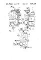
- FIG. 1 is a perspective view of a fuel conditioner embodying the present invention.
- FIG. 2 is a rear view of the fuel conditioner shown in FIG. 1.
- FIG. 3 is a left side elevational view of the fuel conditioner shown in FIG. 1.
- FIG. 4 is a front view of the fuel conditioner shown in partial vertical section and with the disposable filter/water separator cartridge removed.
- FIG. 5 is a somewhat schematic exploded view of the fuel conditioner and illustrates the fuel flowpath therethrough.
- FIG. 6 is a somewhat enlarged sectional view through the disposable filter/water separator cartridge taken along the line 6--6 of FIG. 3.
- FIG. 7 is a somewhat enlarged rear view of the disposable filter/water separator cartridge.
- FIG. 8 is a sectional view taken generally along the line 8--8 of FIG. 6, positioning bosses on the base being shown in phantom.
- FIG. 9 is a sectional view taken along the line 9-9 of FIG. 6, positioning bosses on the base being shown in phantom.
- FIG. 10 is a somewhat enlarged fragmentary sectional view of the fuel conditioner as shown in FIG. 4.
- FIG. 11 is a fragmentary sectional view taken along the line 11--11 of FIG. 3.
- a modular fuel conditioner embodying the present invention is indicated generally by the reference numeral 10.
- the illustrated fuel conditioner 10 is particularly adapted for connection in the fuel system for a diesel engine, (not shown) such as may be used in an automotive, agricultural, power, construction or marine application, and includes a base, indicated generally at 12.
- the fuel conditioner is adapted for mounting in a vertically disposed position on a supporting structure, such as the firewall of an engine compartment, and further includes a throwaway filter/water separator element or disposable cartridge, designated generally by the numeral 14, which contains fuel filter media and coalescing material for concentrating water disbursed in the fuel for collection within the cartridge and ultimate removal from the system.
- Spring retaining clips 16, 16, mounted on the base 12 releasably retain the disposable cartridge 14 in assembly with the base and in fluid communication with passageways in the base, as will be hereinafter more fully described.
- a heater is preferably provided and mounted in the base to heat fuel before it enters the cartridge 14 and thereby protect the filter media from wax plugging in cold environments when temperatures fall below fuel “cloud point”.
- the heater 18 has a heating element 19, best shown in FIG. 4.
- a filter change signalling device 20 is activated to operate a remote signal, such as a signal lamp (not shown), to indicate the necessity for changing the throwaway cartridge.
- a manually operable priming pump 22 mounted on the base 12 of the illustrated fuel conditioner facilitates priming of the fuel system after a cartridge has been changed or the occurrence of fuel exhaustion.
- the priming pump 22 also provides a convenient means for expelling water collected within the fuel conditioner.
- Another signal device or water sensor 24 operates another remote signal, such as a signal lamp (not shown), when a predetermined quantity of water has collected within the fuel conditioner, to provide early warning that the fuel conditioner should be drained before an excessive amount of water has accumulated.
- a drain cock 23 mounted on the base 12 is provided for draining water which accumulates within the fuel conditioner.
- a venting means indicated generally at 25 is also provided for venting air from the fuel conditioner 10.
- the throwaway cartridge 14 is adapted for plugging connection with the base 12 in fluid communication with passageways formed in the base, as will be hereinafter more fully described.
- the cartridge 14 has a generally rectangular housing, indicated generally at 26, which includes a rectangular cup-shaped front portion 28 and a rear wall 30 joined in assembly with the front portion to form a sealed container which defines a generally rectangular filter chamber 32.
- a filter assembly, indicated generally at 34, and contained within the filter chamber 32, extends transversely across the housing 26 and is sealed to associated walls of the housing by a suitable sealing compound 35 to separate the upper portion of the chamber from the lower portion, which defines a sump 36.
- the filter assembly 34 essentially comprises a primary filter element 38 and a coalescing element 40, disposed between the primary filter element and the sump.
- the illustrated filter assembly 34 further includes a generally horizontally disposed secondary filter element 42 located between the primary element 38 and the coalescing element 40.
- Each of the filter elements is made from treated filter paper having a multiplicity of closely spaced pleats and a rectangular block-shaped form.
- the coalescing media is a nylon material arranged in serpentine pleats, substantially as shown.
- An inverted generally U-shaped baffle 43 made from metal or other liquid impervious material, extends between the front and rear walls of the housing 26 adjacent one side of the coalescing element 40 and defines a fluid outlet region of the filter chamber, indicated at 44 and best shown in FIGS. 5 and 6.
- a plurality of elastomeric sealing grommets mounted in apertures in the rear wall 30 define inlet and outlet ports in the housing and are adapted for plugging connection in fluid communication with associated tubular connecting members which project in forward direction from the front of the base 12 and which define terminal ends of passageways in the base.
- One grommet located near the upper end of the housing defines a fluid inlet port 46 which communicates with the upper portion of the filter chamber 32.
- Another grommet communicates with the fluid outlet region 44 and defines a fluid outlet port 48.
- Still another grommet located near the bottom wall of the housing 26 defines a drain port 50 in communication with the sump 36.
- Another grommet defines a port 52 for receiving a probe associated with the signalling device or water sensor 24.
- the base 12 may be made from any suitable material but preferably comprises a metal casting and has a plurality of rearwardly projecting bosses 53, 53 which may be selectively drilled and tapped to suit the particular mounting requirements for a desired installation. Additional bosses 55, 55 project in a forward direction from the base and engage the rear wall 30, as shown in phantom in FIGS. 8 and 9, to assure proper positioning of the cartridge 14 in assembly with the base.
- a plurality of tubular connecting members which define terminal ends of passageways within the base project forwardly from the base for plugging connection in fluid communication with the various ports defined by the grommets in the rear wall 30 whereby fluid communication is established between the various passageways in the base 12 and the filter chamber 32.
- a fluid inlet fitting 54 mounted on the base 12 communicates with an inlet passageway, indicated generally at 56, formed in the base and partially defined by a heating chamber 58. More specifically, the inlet passageway 56 includes a first portion 60 which communicates with an upper portion of the heating chamber 58 and with the inlet fitting 54. A second portion of the inlet passageway, indicated by the numeral 62, communicates with a lower portion of the heating chamber 58 and with the priming pump 22 which is mounted on the upper part of the base 12.
- venting means 25 comprises a vent passageway 80, best shown in FIG. 4, which communicates with the outlet passageway 66 and has a vent outlet 65.
- a vent plug 67 is threadably engaged in the base 12 and seats on an elastomeric seal 81 at the upper end of the passageway 80.
- Another vent passageway 64 communicates with the heating chamber 58 above the heating element 19 and with the inlet passageway 56 and prevents any air which may enter the fuel conditioner from accumulating within the heating chamber.
- the priming pump 22 comprises a diaphragm pump and includes associated check valves which assure unidirectional flow within the inlet passageway and in the direction indicated by the flow arrows in FIG. 5.
- a return or outlet passageway 66 formed in the base 12 provides communication between a tubular connecting number 68 which projects into the outlet port 48 from the base and a fluid outlet fitting 70 on the base to provide a return flow path from the cartridge 14, as indicated by the directional arrows in FIG. 5.
- a drain passageway 72 formed in the base 12 terminates at a forwardly projecting tubular connecting member or drain connection 73 which is received within the drain outlet 50.
- the opposite end of the drain passageway 72 is connected to the manually operable drain cock 23 located on the lower portion of the base as shown in FIG. 11.
- the location of the drain cock is optional.
- the drain cock 23 is shown located in the bottom of the base. However, it may be located in the lower portion of the base at either side of the base, or on the rearward side, as may be necessary for a particular installation.
- the sump defines a water collection region of the housing with a capacity of approximately 250 cc.
- water sensor signal level is preferably set at 50 cc to provide an early alert of water ingress.
- the filter change signal device 20 comprises a vacuum switch mounted within a recess in the base 12 in communication with the return passageway 66.
- the vacuum switch includes an associated electrical connector for connection to a power source and an associated signal lamp, for example, to signal the occurrence of an excessive pressure drop in the return flow passageway which indicates filter plugging.
- the heater 18 is activated within a range of predetermined temperatures based upon anticipated fuel cloud points.
- Fuel which may be heated, enters the cartridge 14 at the upper end of the filter chamber 32 and flows down through the two-stage filter assembly after which it passes through the third stage or coalescing element where water in the fuel coalesces and drops into the sump holding region. Clean fuel returns to the base 12 through the return line 66 and leaves the fuel conditioner through the fluid outlet 70.
- the manually operated priming pump 22 facilitates priming the fuel conditioner 10 after a cartridge has been replaced.
- the vent plug 67 is opened to allow air to escape from the vent passageway 80.
- the priming pump 22 is then manually operated to pump fuel into the new cartridge and to expel air from the cartridge and associated fuel lines. When all air has been expelled the vent plug is closed to restore the system to normal operation.
- the priming pump may also be used to expel air from another part of the fuel supply system, as, for example when some component of the fuel supply system has been removed for replacement. In this instance it may not be necessary to open the vent plug.
- the priming pump 22 may also be used to expel water from the fuel conditioner 10.
- the water sensor 24 When the water sensor 24 is actuated, indicating that at least 50 cc of water has accumulated in the sump 36, the water drain cock 23 is opened and the manually operated priming pump 22 is operated to forceably expel water collected in the sump.
- the cock When water ceases to flow from the drain cock 23, the cock is closed to restore the fuel conditioner to normal operation.
- the priming pump 22 may be operated to restore the fuel supply system to normal operation after the supply of fuel has been replenished.
Landscapes
- Engineering & Computer Science (AREA)
- Chemical & Material Sciences (AREA)
- Chemical Kinetics & Catalysis (AREA)
- Combustion & Propulsion (AREA)
- Mechanical Engineering (AREA)
- General Engineering & Computer Science (AREA)
- Physics & Mathematics (AREA)
- Thermal Sciences (AREA)
- Filtration Of Liquid (AREA)
- Feeding And Controlling Fuel (AREA)
Abstract
Description
Claims (13)
Priority Applications (2)
| Application Number | Priority Date | Filing Date | Title |
|---|---|---|---|
| US06/507,799 US4491120A (en) | 1983-06-24 | 1983-06-24 | Fuel conditioner |
| US06/696,643 US4618423A (en) | 1983-06-24 | 1984-12-27 | Disposable fuel filter/water separator element |
Applications Claiming Priority (1)
| Application Number | Priority Date | Filing Date | Title |
|---|---|---|---|
| US06/507,799 US4491120A (en) | 1983-06-24 | 1983-06-24 | Fuel conditioner |
Related Child Applications (1)
| Application Number | Title | Priority Date | Filing Date |
|---|---|---|---|
| US06/696,643 Division US4618423A (en) | 1983-06-24 | 1984-12-27 | Disposable fuel filter/water separator element |
Publications (1)
| Publication Number | Publication Date |
|---|---|
| US4491120A true US4491120A (en) | 1985-01-01 |
Family
ID=24020183
Family Applications (1)
| Application Number | Title | Priority Date | Filing Date |
|---|---|---|---|
| US06/507,799 Expired - Lifetime US4491120A (en) | 1983-06-24 | 1983-06-24 | Fuel conditioner |
Country Status (1)
| Country | Link |
|---|---|
| US (1) | US4491120A (en) |
Cited By (29)
| Publication number | Priority date | Publication date | Assignee | Title |
|---|---|---|---|---|
| USD284300S (en) | 1983-06-24 | 1986-06-17 | Stanadyne, Inc. | Filter cartridge |
| US4898668A (en) * | 1988-09-30 | 1990-02-06 | Stanadyne Automotive Corp. | Fuel filter with heater |
| US4956081A (en) * | 1988-09-30 | 1990-09-11 | Stanadyne Automotive Corp. | Fuel filter with diaphragm pump |
| EP0362114A3 (en) * | 1988-09-30 | 1990-09-26 | Stanadyne Automotive Corp. | Back-to-back fuel filter and water separator |
| US5017285A (en) * | 1989-06-28 | 1991-05-21 | Stanadyne Automotive Corp. | Fuel filter and cartridge assembly |
| US5084170A (en) * | 1989-09-08 | 1992-01-28 | Stanadyne Automotive Corp. | Fuel filter |
| US5362392A (en) * | 1993-03-08 | 1994-11-08 | Parker Hannifin Corporation | Filter head with integral priming pump |
| US5462658A (en) * | 1994-01-14 | 1995-10-31 | Thermo King Corporation | Fuel filter system |
| US5922199A (en) * | 1993-09-15 | 1999-07-13 | Parker Hannifin Corporation | Double pass fuel filter assembly |
| US6159383A (en) * | 1998-04-17 | 2000-12-12 | Caterpillar Inc. | Filter head assembly |
| US6328883B1 (en) | 2000-05-31 | 2001-12-11 | Parker-Hannifin Corporation | Fuel filter assembly with priming pump |
| FR2829704A1 (en) * | 2001-09-19 | 2003-03-21 | Delphi Tech Inc | FILTRATION DEVICE WITH IMPROVED PURGE ASSEMBLY AND GAS SUPPLY LINE COMPRISING SUCH A DEVICE |
| FR2829803A1 (en) * | 2001-09-19 | 2003-03-21 | Delphi Tech Inc | Filter for motor vehicle Diesel fuel feed has heater and filter casings connected by sliding fit stub |
| WO2003035217A1 (en) * | 2001-09-19 | 2003-05-01 | Delphi Technologies, Inc. | Filtering device with enhanced bleeding assembly and diesel fuel supply line comprising same |
| WO2005010339A1 (en) * | 2003-07-22 | 2005-02-03 | Robert Bosch Gmbh | Modular fuel filter |
| EP1557556A1 (en) * | 2004-01-20 | 2005-07-27 | Robert Bosch Gmbh | Filter with actuating element for purging separated water |
| US20060006106A1 (en) * | 2004-07-09 | 2006-01-12 | Flo-Rite Fluids, Inc. | Fluid conditioning system and method |
| US20060027489A1 (en) * | 2004-08-09 | 2006-02-09 | Felix Libfeld | 24-Volt pump adapter |
| US20070084776A1 (en) * | 2005-09-30 | 2007-04-19 | Sasur Timothy M | Water separation and filtration structure |
| US20080277352A1 (en) * | 2007-05-08 | 2008-11-13 | Flo-Rite Fluids, Inc. | Magnetic Water Conditioner |
| US20090165752A1 (en) * | 2007-12-27 | 2009-07-02 | Denso Corporation | Fuel feed apparatus |
| US20120216778A1 (en) * | 2011-02-28 | 2012-08-30 | Ford Global Technologies, Llc | Multi-staged fuel return system |
| US9550135B2 (en) | 2013-01-14 | 2017-01-24 | Clarcor Engine Mobile Solutions, Llc | Fuel filter assembly and cartridge |
| US9675908B2 (en) | 2013-01-14 | 2017-06-13 | Clarcor Engine Mobile Solutions, Llc | Fuel filter assembly and cartridge |
| EP3320960A1 (en) * | 2016-11-15 | 2018-05-16 | Sogefi Engine Systems USA, Inc. | Serviceable diesel fuel filter assembly |
| US10233882B2 (en) | 2015-09-08 | 2019-03-19 | Sogefi Engine Systems Usa, Inc. | Serviceable diesel fuel filter assembly |
| US10253738B2 (en) | 2015-09-08 | 2019-04-09 | Sogefi Engine Systems Usa, Inc. | Diesel fuel filter assembly |
| US11125035B2 (en) | 2015-05-20 | 2021-09-21 | Flo-Rite Fluids, Inc. | Method and system for positioning a magnetic fluid conditioner |
| US11459986B2 (en) * | 2018-09-24 | 2022-10-04 | Baldwin Filters, Inc. | Obround filter element |
Citations (7)
| Publication number | Priority date | Publication date | Assignee | Title |
|---|---|---|---|---|
| US48172A (en) * | 1865-06-13 | Improved filter for oils | ||
| US1831075A (en) * | 1926-10-20 | 1931-11-10 | Griffin Watkins | Means of removing scale matter from liquids |
| US3417015A (en) * | 1966-11-22 | 1968-12-17 | Exxon Research Engineering Co | Coalescer and separator for oily water |
| US4338907A (en) * | 1981-08-28 | 1982-07-13 | Lindbeck Laurel B | Gasoline fume generator and mixer |
| US4368716A (en) * | 1980-09-19 | 1983-01-18 | Davco, Inc. | Fuel processor apparatus for diesel powered vehicles |
| US4395996A (en) * | 1981-10-16 | 1983-08-02 | Davco Incorporated | Fuel supply and conditioning means for diesel engines |
| US4428351A (en) * | 1980-09-19 | 1984-01-31 | Davco, Inc. | Fuel processor apparatus |
-
1983
- 1983-06-24 US US06/507,799 patent/US4491120A/en not_active Expired - Lifetime
Patent Citations (7)
| Publication number | Priority date | Publication date | Assignee | Title |
|---|---|---|---|---|
| US48172A (en) * | 1865-06-13 | Improved filter for oils | ||
| US1831075A (en) * | 1926-10-20 | 1931-11-10 | Griffin Watkins | Means of removing scale matter from liquids |
| US3417015A (en) * | 1966-11-22 | 1968-12-17 | Exxon Research Engineering Co | Coalescer and separator for oily water |
| US4368716A (en) * | 1980-09-19 | 1983-01-18 | Davco, Inc. | Fuel processor apparatus for diesel powered vehicles |
| US4428351A (en) * | 1980-09-19 | 1984-01-31 | Davco, Inc. | Fuel processor apparatus |
| US4338907A (en) * | 1981-08-28 | 1982-07-13 | Lindbeck Laurel B | Gasoline fume generator and mixer |
| US4395996A (en) * | 1981-10-16 | 1983-08-02 | Davco Incorporated | Fuel supply and conditioning means for diesel engines |
Cited By (45)
| Publication number | Priority date | Publication date | Assignee | Title |
|---|---|---|---|---|
| USD284300S (en) | 1983-06-24 | 1986-06-17 | Stanadyne, Inc. | Filter cartridge |
| US4898668A (en) * | 1988-09-30 | 1990-02-06 | Stanadyne Automotive Corp. | Fuel filter with heater |
| US4956081A (en) * | 1988-09-30 | 1990-09-11 | Stanadyne Automotive Corp. | Fuel filter with diaphragm pump |
| EP0362114A3 (en) * | 1988-09-30 | 1990-09-26 | Stanadyne Automotive Corp. | Back-to-back fuel filter and water separator |
| EP0360973A3 (en) * | 1988-09-30 | 1991-03-06 | Stanadyne Automotive Corp. | Fuel filter with diaphragm pump |
| US5017285A (en) * | 1989-06-28 | 1991-05-21 | Stanadyne Automotive Corp. | Fuel filter and cartridge assembly |
| US5084170A (en) * | 1989-09-08 | 1992-01-28 | Stanadyne Automotive Corp. | Fuel filter |
| EP0688594A2 (en) | 1989-09-08 | 1995-12-27 | Stanadyne Automotive Corp. | Fuel filter |
| US5362392A (en) * | 1993-03-08 | 1994-11-08 | Parker Hannifin Corporation | Filter head with integral priming pump |
| US5922199A (en) * | 1993-09-15 | 1999-07-13 | Parker Hannifin Corporation | Double pass fuel filter assembly |
| US6248236B1 (en) | 1993-09-15 | 2001-06-19 | Parker-Hannifin Corporation | Double pass fuel filter assembly |
| US5462658A (en) * | 1994-01-14 | 1995-10-31 | Thermo King Corporation | Fuel filter system |
| US6159383A (en) * | 1998-04-17 | 2000-12-12 | Caterpillar Inc. | Filter head assembly |
| US6328883B1 (en) | 2000-05-31 | 2001-12-11 | Parker-Hannifin Corporation | Fuel filter assembly with priming pump |
| FR2829704A1 (en) * | 2001-09-19 | 2003-03-21 | Delphi Tech Inc | FILTRATION DEVICE WITH IMPROVED PURGE ASSEMBLY AND GAS SUPPLY LINE COMPRISING SUCH A DEVICE |
| US7048851B2 (en) * | 2001-09-19 | 2006-05-23 | Delphi Technologies, Inc. | Device for filtering diesel fuel that is intended to supply a diesel engine and a diesel fuel supply line comprising one such device |
| WO2003025381A1 (en) | 2001-09-19 | 2003-03-27 | Delphi Technologies Inc. | Device for filtering diesel fuel that is intended to supply a diesel engine and a diesel fuel supply line comprising one such device |
| WO2003035217A1 (en) * | 2001-09-19 | 2003-05-01 | Delphi Technologies, Inc. | Filtering device with enhanced bleeding assembly and diesel fuel supply line comprising same |
| US20050005584A1 (en) * | 2001-09-19 | 2005-01-13 | Daniel Decaux | Filtering device with enhanced bleeding assembly and diesel fuel supply line comprising same |
| FR2829803A1 (en) * | 2001-09-19 | 2003-03-21 | Delphi Tech Inc | Filter for motor vehicle Diesel fuel feed has heater and filter casings connected by sliding fit stub |
| US7323037B2 (en) | 2001-09-19 | 2008-01-29 | Delphi Technologies, Inc. | Filtering device with enhanced bleeding assembly and diesel fuel supply line comprising same |
| WO2005010339A1 (en) * | 2003-07-22 | 2005-02-03 | Robert Bosch Gmbh | Modular fuel filter |
| EP1557556A1 (en) * | 2004-01-20 | 2005-07-27 | Robert Bosch Gmbh | Filter with actuating element for purging separated water |
| US20060006106A1 (en) * | 2004-07-09 | 2006-01-12 | Flo-Rite Fluids, Inc. | Fluid conditioning system and method |
| WO2006010124A3 (en) * | 2004-07-09 | 2007-01-25 | Flo Rite Fluids Inc | Fluid conditioning system and method |
| US7572371B2 (en) | 2004-07-09 | 2009-08-11 | Flo-Rite Fluids, Inc. | Fluid conditioning system and method |
| US20080149548A1 (en) * | 2004-07-09 | 2008-06-26 | Flo-Rite Fluids, Inc. | Fluid Conditioning System and Method |
| US7357862B2 (en) * | 2004-07-09 | 2008-04-15 | Flo-Rite Fluids, Inc. | Fluid conditioning system and method |
| US20060027489A1 (en) * | 2004-08-09 | 2006-02-09 | Felix Libfeld | 24-Volt pump adapter |
| WO2007041559A3 (en) * | 2005-09-30 | 2007-11-08 | Stanadyne Corp | Water separation and filtration structure |
| US20070084776A1 (en) * | 2005-09-30 | 2007-04-19 | Sasur Timothy M | Water separation and filtration structure |
| US20080277352A1 (en) * | 2007-05-08 | 2008-11-13 | Flo-Rite Fluids, Inc. | Magnetic Water Conditioner |
| US9039901B2 (en) | 2007-05-08 | 2015-05-26 | Flo-Rite Fluids, Inc. | Magnetic water conditioner |
| US20090165752A1 (en) * | 2007-12-27 | 2009-07-02 | Denso Corporation | Fuel feed apparatus |
| US7743751B2 (en) * | 2007-12-27 | 2010-06-29 | Denso Corporation | Fuel feed apparatus |
| US20120216778A1 (en) * | 2011-02-28 | 2012-08-30 | Ford Global Technologies, Llc | Multi-staged fuel return system |
| US9157393B2 (en) * | 2011-02-28 | 2015-10-13 | Ford Global Technologies, Llc | Multi-staged fuel return system |
| US9550135B2 (en) | 2013-01-14 | 2017-01-24 | Clarcor Engine Mobile Solutions, Llc | Fuel filter assembly and cartridge |
| US9675908B2 (en) | 2013-01-14 | 2017-06-13 | Clarcor Engine Mobile Solutions, Llc | Fuel filter assembly and cartridge |
| US11125035B2 (en) | 2015-05-20 | 2021-09-21 | Flo-Rite Fluids, Inc. | Method and system for positioning a magnetic fluid conditioner |
| US11965387B2 (en) | 2015-05-20 | 2024-04-23 | Flo-Rite Fluids, Inc. | Method and system for positioning a magnetic fluid conditioner |
| US10233882B2 (en) | 2015-09-08 | 2019-03-19 | Sogefi Engine Systems Usa, Inc. | Serviceable diesel fuel filter assembly |
| US10253738B2 (en) | 2015-09-08 | 2019-04-09 | Sogefi Engine Systems Usa, Inc. | Diesel fuel filter assembly |
| EP3320960A1 (en) * | 2016-11-15 | 2018-05-16 | Sogefi Engine Systems USA, Inc. | Serviceable diesel fuel filter assembly |
| US11459986B2 (en) * | 2018-09-24 | 2022-10-04 | Baldwin Filters, Inc. | Obround filter element |
Similar Documents
| Publication | Publication Date | Title |
|---|---|---|
| US4491120A (en) | Fuel conditioner | |
| US4618423A (en) | Disposable fuel filter/water separator element | |
| US4976852A (en) | Fuel filter | |
| US5084170A (en) | Fuel filter | |
| US4860713A (en) | Back-to-back fuel filter and water separator | |
| US5017285A (en) | Fuel filter and cartridge assembly | |
| EP1144074B1 (en) | Fuel filter system with water bleed and water trap | |
| US4515690A (en) | Fuel supply system for diesel engines | |
| US4437986A (en) | Separating device and cartridge therefor | |
| US6514404B1 (en) | Filter device | |
| US5922199A (en) | Double pass fuel filter assembly | |
| US4997555A (en) | Fuel filter assembly with heater | |
| EP1154149B1 (en) | Integrated fuel pump and fuel filter | |
| US5622623A (en) | Fuel filter element | |
| US5740784A (en) | Fuel control system | |
| US4732671A (en) | Diesel fuel filter/water separator | |
| US4579653A (en) | Side-by-side fuel processor apparatus | |
| EP0560801B1 (en) | Modular lubrication/filter system | |
| EP0285416A1 (en) | Fuel filter assembly with heater | |
| KR20050096945A (en) | Evaporation unit for a fuel filter | |
| EP0138578B1 (en) | Condensers for compressed gas systems | |
| EP0844382A2 (en) | Fuel filter | |
| JPS59108860A (en) | Fuel heating apparatus for diesel engine | |
| KR20010062955A (en) | Diesel fuel filter | |
| GB2118059A (en) | Fuel filter units |
Legal Events
| Date | Code | Title | Description |
|---|---|---|---|
| AS | Assignment |
Owner name: STANADYNE, INC. 100 DEERFIELD ROAD, WINDSOR, CT 0 Free format text: ASSIGNMENT OF ASSIGNORS INTEREST.;ASSIGNOR:HODGKINS, DAVID;REEL/FRAME:004146/0522 Effective date: 19830621 |
|
| STCF | Information on status: patent grant |
Free format text: PATENTED CASE |
|
| FEPP | Fee payment procedure |
Free format text: PAYOR NUMBER ASSIGNED (ORIGINAL EVENT CODE: ASPN); ENTITY STATUS OF PATENT OWNER: LARGE ENTITY |
|
| FPAY | Fee payment |
Year of fee payment: 4 |
|
| AS | Assignment |
Owner name: MANUFACTURERS HANOVER TRUST COMPANY, AS AGENT Free format text: SECURITY INTEREST;ASSIGNOR:STANADYNE AUTOMOTIVE CORP.;REEL/FRAME:005046/0096 Effective date: 19890210 |
|
| AS | Assignment |
Owner name: STANADYNE AUTOMOTIVE CORP., A CORP. OF DE, CONNECT Free format text: ASSIGNMENT OF ASSIGNORS INTEREST.;ASSIGNOR:STANADYNE, INC.;REEL/FRAME:005130/0582 Effective date: 19890210 |
|
| FEPP | Fee payment procedure |
Free format text: PAYER NUMBER DE-ASSIGNED (ORIGINAL EVENT CODE: RMPN); ENTITY STATUS OF PATENT OWNER: LARGE ENTITY Free format text: PAYOR NUMBER ASSIGNED (ORIGINAL EVENT CODE: ASPN); ENTITY STATUS OF PATENT OWNER: LARGE ENTITY |
|
| FPAY | Fee payment |
Year of fee payment: 8 |
|
| AS | Assignment |
Owner name: BANK OF NEW YORK, THE, NEW YORK Free format text: SECURITY INTEREST;ASSIGNOR:STANADYNE AUTOMOTIVE CORP.;REEL/FRAME:007297/0191 Effective date: 19950202 Owner name: STANADYNE INC., CONNECTICUT Free format text: RELEASE OF SECURITY INTEREST;ASSIGNOR:CHEMICAL BANK, AS SUCCESSOR IN INTEREST TO MANUFACTURERS HANOVER TRUST COMPANY;REEL/FRAME:007308/0169 Effective date: 19950201 |
|
| FPAY | Fee payment |
Year of fee payment: 12 |
|
| AS | Assignment |
Owner name: FIRST NATIONAL BANK OF CHICAGO, THE, NEW YORK Free format text: PATENT SECURITY AGREEMENT;ASSIGNOR:STANADYNE AUTOMOTIVE CORP.;REEL/FRAME:008907/0273 Effective date: 19971211 |
|
| AS | Assignment |
Owner name: STANDAYNE CORPORATION, CONNECTICUT Free format text: CHANGE OF NAME;ASSIGNOR:STANADYNE AUTOMOTIVE CORP.;REEL/FRAME:012391/0570 Effective date: 20010711 |
|
| AS | Assignment |
Owner name: STANADYNE CORPORATIN, CONNECTICUT Free format text: RELEASE BY SECURED PARTY;ASSIGNOR:BANK OF NEW YORK, THE;REEL/FRAME:015083/0817 Effective date: 20040813 |