US4480758A - Railway coupler arrangement - Google Patents
Railway coupler arrangement Download PDFInfo
- Publication number
- US4480758A US4480758A US06/438,581 US43858182A US4480758A US 4480758 A US4480758 A US 4480758A US 43858182 A US43858182 A US 43858182A US 4480758 A US4480758 A US 4480758A
- Authority
- US
- United States
- Prior art keywords
- draft
- draft gear
- follower
- gear housing
- lugs
- Prior art date
- Legal status (The legal status is an assumption and is not a legal conclusion. Google has not performed a legal analysis and makes no representation as to the accuracy of the status listed.)
- Expired - Fee Related
Links
- 230000008878 coupling Effects 0.000 abstract 1
- 238000010168 coupling process Methods 0.000 abstract 1
- 238000005859 coupling reaction Methods 0.000 abstract 1
- 238000005266 casting Methods 0.000 description 2
- 230000000694 effects Effects 0.000 description 2
- 230000035939 shock Effects 0.000 description 2
- 239000006096 absorbing agent Substances 0.000 description 1
- 230000014759 maintenance of location Effects 0.000 description 1
Images


Classifications
-
- B—PERFORMING OPERATIONS; TRANSPORTING
- B61—RAILWAYS
- B61G—COUPLINGS; DRAUGHT AND BUFFING APPLIANCES
- B61G1/00—Couplings comprising interengaging parts of different shape or form and having links, bars, pins, shackles, or hooks as coupling means
- B61G1/36—Couplings comprising interengaging parts of different shape or form and having links, bars, pins, shackles, or hooks as coupling means with shackles and hooks, e.g. specially adapted for mine cars
- B61G1/38—Couplings comprising interengaging parts of different shape or form and having links, bars, pins, shackles, or hooks as coupling means with shackles and hooks, e.g. specially adapted for mine cars rotatable about line of traction, e.g. for cars which are tiltable when coupled
Definitions
- the coupler head is connected through a shank to a yoke having a yoke strap which envelops a draft gear (i.e., a spring arrangement which absorbs shock loads).
- the draft gear in turn, is carried within a sill which is secured to the car body and is provided with front and rear draft lugs between which the draft gear can slide.
- draft loads i.e., pulling loads
- the yoke strap forces the draft gear against the front draft lugs and compresses the draft gear.
- buff loads i.e., pushing loads
- the yoke pushes the draft gear against the rear draft lugs, again compressing it, but in the opposite sense.
- a rotary coupler which permits an entire hopper car, for example, to be rotated and turned upside-down to discharge its contents without decoupling it from forward and aft cars.
- Many types of rotary couplers have been devised as exemplified by U.S. Pat. Nos. 3,104,017 and 4,090,614. In many of these designs, problems have been encountered because of the limited area available for the rotary connection between the front draft lugs. Other designs utilize the space at the coupler head to obtain adequate room for the rotary connection. In either case, design constraints either limit the diameter of the rotary shank or butt area (which are critical factors), or involve other drawbacks.
- a new and improved railway coupler arrangement is provided wherein the conventional yoke and draft gear arrangement is modified. This enables a larger draft gear to be positioned within the sill and reduces the cost of the casting which forms the yoke.
- a new and improved rotary coupler arrangement wherein the rotary connection is positioned just aft of the front draft lugs on a sill or striker.
- This arrangement permits at least a 61/2 inch diameter rotary shank as well as a two-inch wide shoulder bearing area for the rotary connection.
- This is in contrast to prior art rotary coupler arrangements of this type wherein the diameter of the shank is ordinarily less than 53/4 inches, giving rise to possible field failures.
- a railway coupler arrangement comprising a center sill having front and rear draft lugs within the sill.
- a draft gear housing is carried within the sill and is slideable between the front and rear draft lugs.
- a follower and plunger block is slideable in the center sill and is in engagement with one end of a draft gear carried within the draft gear housing.
- a yoke shank extends into the draft gear housing and is provided with a butt engageable with the aforesaid follower and plunger block and is movable from a position where it engages forward wall means on the draft gear housing during draft loads to a position removed from the forward wall means where it forces the follower and plunger block into the draft gear during buff loads.
- Means are associated with the front draft lugs for engaging the follower and plunger block during draft loads to compress the draft gear.
- the means for engaging the follower and plunger block during draft loads preferably comprises keys which extend between the front draft lugs and are engageable with the follower and plunger block during draft loads as the draft gear housing moves forwardly. As the housing does move forwardly, the keys restrain the follower and plunger block to compress the draft gear and provide a cushioning effect.
- a rotary coupler arrangement wherein the railway coupler shank is provided with a butt end which extends into the draft gear housing and which is engageable with a cooperating spherical surface on the follower and plunger block.
- the rotary coupler butt end is disposed aft of the front draft gear lugs on the sills such that its diameter may be maximized.
- FIG. 1 is a top view of a railway coupler assembly incorporating the invention
- FIG. 2 is an exploded view of the draft gear housing and yoke of the invention
- FIG. 3 is a top cross-sectional view of the invention showing the yoke and the draft gear when essentially no load is imposed on the coupler;
- FIG. 4 is a view similar to that of FIG. 3 showing the positions of the parts when the coupler is under a draft load;
- FIG. 5 is a view similar to FIG. 3 but showing the parts of the invention when the coupler is under a buff load;
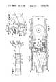
- FIG. 6 is a cross-sectional view of another embodiment of the invention.
- FIG. 7 is a cross-sectional view taken substantially along line VII--VII of FIG. 6;
- FIG. 8 is a cross-sectional view taken substantially along line VIII--VIII of FIG. 6;
- FIG. 9 is a side view of the front of the draft gear housing as viewed substantially along line IX--IX of FIG. 6;
- FIG. 10 is a cross-sectional view taken substantially along line X--X of FIG. 6 showing the arrangement of the horizontal and vertical keys used in the embodiment of FIG. 6.
- a railway coupler head 10 provided with a shank 12, is pivotally connected at 14 to the modified yoke 16 of the invention.
- a key-slotted or E-type coupler design can be incorporated into the invention as well as the pin-connected or F-type coupler shown herein.
- the yoke 16 is circular in cross-sectional configuration and does not include a conventional yoke strap. Rather, the cylindrical yoke 16 terminates in a rotary butt 18 having a rear spherical face 20 (FIG. 4) which is adapted to seat on a corresponding spherical surface 21 formed in a transversely-extending follower and plunger block 22.
- the butt 18 and plunger block 22 are carried within the forward portion of a draft gear housing 24 slideable within the side walls 26 and 28 of a center sill 30 secured to the underside of a railway car in accordance with conventional practice.
- a striker 32 Received within the forward end of the sill 30 is a striker 32, as is conventional.
- the details of the draft gear housing 24 are perhaps best shown in FIGS. 2 and 3. It includes a cavity 34 within which is received a draft gear 36 (FIG. 3) which is essentially a spring-type shock absorber in accordance with conventional practice. Laterally-extended surfaces 35 and 38 on the housing 34 are adapted to abut near draft lugs 40 and 42 carried on the insides of the sill walls 26 and 28. At the forward end of the housing 24 is a cavity 44 within which the butt 18 and follower and plunger 22 are disposed. The cavity 44 is formed by top and bottom walls and side walls 46 each of which is provided with an elongated opening 48 through which an end of the follower 22 extends. The openings 48, in turn, communicate with slots 50 which, as shown in FIG.
- the cavity 44 of the draft gear housing 24 includes a front wall 64 formed with a slotted, semi-circular opening 66 which receives the cylindrical shank 16.
- the shank is held in place by an upper block 68 formed with an upper semi-circular opening 70 which mates with the lower opening 66.
- the block 68 is secured to a cover plate 72 received within opening 74.
- the cover plate 72 can be held in place within the opening 74 by suitable fastening means, not shown.
- FIG. 3 the various parts of the invention are shown when the coupler is under neither draft nor buff loads. Under these circumstances, the ends of the follower and plunger block 22 are essentially midway between the ends of the openings 48 while the draft gear 36 is essentially uncompressed. In FIG. 4, the parts are shown under draft load conditions. Under these circumstances, the butt engages the forward wall 64 of the draft gear housing 24 and pulls it forwardly such that the surfaces 35 and 38 of the draft gear housing disengage from the rear draft lugs 42 and 44 on the sill 30. By virtue of the keys 52 and 54 which engage the forward draft lugs 56 and 58, the follower and plunger block 22 cannot move forwardly with the draft gear housing 24. As a result, the draft gear 36, which attempts to move forwardly with the housing 24, is compressed, providing a cushioning effect during draft loads.
- FIG. 5 the positions of the various parts during buff loading are shown.
- the surfaces 35 and 38 on the draft gear housing 24 engage the rear draft lugs 40 and 42 while the butt 18, under a buff load, forces the follower and plunger block 22 to the left to compress the draft gear 36.
- FIGS. 6-10 another embodiment of the invention is shown wherein elements corresponding to those of FIGS. 1-6 are identified by like reference numerals
- the forward end of the draft gear housing (FIG. 9) is in the form of an open-sided and open-ended casting 76 having top and bottom walls 78 and 80.
- Formed in the top and bottom walls 78 and 80 are grooves or slots 82 which receive two vertical keys 84 and 86 (FIGS. 6 and 10) which are held in place by the spring force exerted on the follower 22 and butt 18 by the draft gear 36.
- Adjacent the keys 84 and 86 are horizontally-extending keys 52 and 54 corresponding to those shown in FIGS. 1-5.
- FIGS. 6-10 is the same as that of FIGS. 1-5.
- the rotary shank 16 and the butt 18 are inserted through the side of the draft gear housing between the upper and lower walls 78 and 80 just ahead of the follower and plunger block 22.
- the rotary shank is then compressed into the housing while compressing the draft gear 36.
- the vertical retention keys 84 and 86 are inserted in place.
- the longitudinally-running draft load keys 52 and 54 are inserted into the front corners of the draft gear housing.
- the draft gear 36 can extend between and beyond the rear draft lugs 40 and 42, thereby increasing the capacity of the draft gear for a given cross-sectional area within the sill 30.
- the height of the draft gear can also be increased due to the fact that a yoke strap is eliminated.
Landscapes
- Engineering & Computer Science (AREA)
- Mechanical Engineering (AREA)
- Gears, Cams (AREA)
Abstract
Description
Claims (5)
Priority Applications (1)
| Application Number | Priority Date | Filing Date | Title |
|---|---|---|---|
| US06/438,581 US4480758A (en) | 1982-11-03 | 1982-11-03 | Railway coupler arrangement |
Applications Claiming Priority (1)
| Application Number | Priority Date | Filing Date | Title |
|---|---|---|---|
| US06/438,581 US4480758A (en) | 1982-11-03 | 1982-11-03 | Railway coupler arrangement |
Publications (1)
| Publication Number | Publication Date |
|---|---|
| US4480758A true US4480758A (en) | 1984-11-06 |
Family
ID=23741193
Family Applications (1)
| Application Number | Title | Priority Date | Filing Date |
|---|---|---|---|
| US06/438,581 Expired - Fee Related US4480758A (en) | 1982-11-03 | 1982-11-03 | Railway coupler arrangement |
Country Status (1)
| Country | Link |
|---|---|
| US (1) | US4480758A (en) |
Cited By (10)
| Publication number | Priority date | Publication date | Assignee | Title |
|---|---|---|---|---|
| US4555033A (en) * | 1983-10-03 | 1985-11-26 | Pullman Standard, Inc. | Slackless non-cushioned drawbar arrangement for railway car underframe |
| US5176268A (en) * | 1991-06-11 | 1993-01-05 | Houston Industries Incorporated | Railroad car draft system assembly having improved wear life |
| USD389093S (en) | 1997-01-09 | 1998-01-13 | Fm Industries, Inc. | Railcar hydraulic shock absorber backstop |
| EP1329371A1 (en) * | 2002-01-21 | 2003-07-23 | Manfred Bartel | Joint for coupling bars of railway freight wagon units |
| US8196762B2 (en) | 2008-05-23 | 2012-06-12 | Bedloe Industries Llc | Knuckle formed without a finger core |
| US8201613B2 (en) | 2008-05-23 | 2012-06-19 | Bedloe Industries Llc | Knuckle formed from pivot pin and kidney core and isolated finger core |
| US8408406B2 (en) | 2008-05-22 | 2013-04-02 | Bedloe Industries Llc | Central datum feature on railroad coupler body and corresponding gauges |
| US8544662B2 (en) | 2008-05-22 | 2013-10-01 | Bedloe Industries Llc | Central datum feature on railroad coupler body and corresponding gauges |
| US8662327B2 (en) | 2008-05-23 | 2014-03-04 | Bedloe Industries Llc | Railway coupler core structure for increased strength and fatigue life of resulting knuckle |
| US8746473B2 (en) | 2008-05-22 | 2014-06-10 | Bedloe Industries Llc | Railway coupler body improvements to improve knuckle rotation |
Citations (4)
| Publication number | Priority date | Publication date | Assignee | Title |
|---|---|---|---|---|
| FR1066058A (en) * | 1950-11-21 | 1954-06-02 | Gutehoffnungshuette Oberhausen | Swiveling pulling and pushing device for wagons to be unloaded not unhooked from each other |
| GB1029368A (en) * | 1964-02-04 | 1966-05-11 | Nat Castings Co | Railway coupler aligning apparatus |
| US3559818A (en) * | 1969-02-14 | 1971-02-02 | Pullman Inc | Hydraulic draft gear |
| US3583573A (en) * | 1969-02-14 | 1971-06-08 | Pullman Inc | End-of-railway-car cushioning installation |
-
1982
- 1982-11-03 US US06/438,581 patent/US4480758A/en not_active Expired - Fee Related
Patent Citations (4)
| Publication number | Priority date | Publication date | Assignee | Title |
|---|---|---|---|---|
| FR1066058A (en) * | 1950-11-21 | 1954-06-02 | Gutehoffnungshuette Oberhausen | Swiveling pulling and pushing device for wagons to be unloaded not unhooked from each other |
| GB1029368A (en) * | 1964-02-04 | 1966-05-11 | Nat Castings Co | Railway coupler aligning apparatus |
| US3559818A (en) * | 1969-02-14 | 1971-02-02 | Pullman Inc | Hydraulic draft gear |
| US3583573A (en) * | 1969-02-14 | 1971-06-08 | Pullman Inc | End-of-railway-car cushioning installation |
Cited By (12)
| Publication number | Priority date | Publication date | Assignee | Title |
|---|---|---|---|---|
| US4555033A (en) * | 1983-10-03 | 1985-11-26 | Pullman Standard, Inc. | Slackless non-cushioned drawbar arrangement for railway car underframe |
| US5176268A (en) * | 1991-06-11 | 1993-01-05 | Houston Industries Incorporated | Railroad car draft system assembly having improved wear life |
| USD389093S (en) | 1997-01-09 | 1998-01-13 | Fm Industries, Inc. | Railcar hydraulic shock absorber backstop |
| EP1329371A1 (en) * | 2002-01-21 | 2003-07-23 | Manfred Bartel | Joint for coupling bars of railway freight wagon units |
| US8408406B2 (en) | 2008-05-22 | 2013-04-02 | Bedloe Industries Llc | Central datum feature on railroad coupler body and corresponding gauges |
| US8544662B2 (en) | 2008-05-22 | 2013-10-01 | Bedloe Industries Llc | Central datum feature on railroad coupler body and corresponding gauges |
| US8746473B2 (en) | 2008-05-22 | 2014-06-10 | Bedloe Industries Llc | Railway coupler body improvements to improve knuckle rotation |
| US8196762B2 (en) | 2008-05-23 | 2012-06-12 | Bedloe Industries Llc | Knuckle formed without a finger core |
| US8201613B2 (en) | 2008-05-23 | 2012-06-19 | Bedloe Industries Llc | Knuckle formed from pivot pin and kidney core and isolated finger core |
| US8631952B2 (en) | 2008-05-23 | 2014-01-21 | Bedloe Industries Llc | Knuckle formed without a finger core |
| US8646631B2 (en) | 2008-05-23 | 2014-02-11 | Bedloe Industries, LLC | Knuckle formed from pivot pin and kidney core and isolated finger core |
| US8662327B2 (en) | 2008-05-23 | 2014-03-04 | Bedloe Industries Llc | Railway coupler core structure for increased strength and fatigue life of resulting knuckle |
Similar Documents
| Publication | Publication Date | Title |
|---|---|---|
| US10246109B2 (en) | Railcar yoke | |
| US4258628A (en) | Articulated railway coupling | |
| US4480758A (en) | Railway coupler arrangement | |
| US5360124A (en) | Slackless buff gear connection system with sliding yoke casting | |
| US7264130B2 (en) | Housing for long travel high capacity friction draft gear assembly | |
| KR101296385B1 (en) | Two piece draft gear housing having an integral yoke | |
| US5152409A (en) | Draft gear assembly | |
| US3104017A (en) | Carrier assembly for rotary coupler | |
| US7097055B2 (en) | Long buff short draft travel draft gear for use in a 24.625 inch pocket | |
| US2686602A (en) | Cushioning mechanism for railway vehicles | |
| US3185317A (en) | Compensating draft gear | |
| US5246135A (en) | Limited slack railcar connector having elastic space member | |
| US2817445A (en) | Friction draft gear | |
| US2908402A (en) | Railway car connector | |
| US2974810A (en) | Shock absorbing device | |
| US2576214A (en) | Shock absorbing mechanism for railway draft riggings | |
| US2850180A (en) | Rotary railway coupler | |
| US2855112A (en) | Rubber draft gears for railway draft rigging | |
| US2987196A (en) | Draft and buffing gear | |
| US2129543A (en) | Car construction | |
| US2811263A (en) | Draft gear combining helical springs, rubber springs, and friction | |
| US3233748A (en) | Centering device for car couplers | |
| US1209188A (en) | Radial-draft gear. | |
| CA1115239A (en) | Housing for draft gear | |
| US2812072A (en) | Draft rigging |
Legal Events
| Date | Code | Title | Description |
|---|---|---|---|
| AS | Assignment |
Owner name: MCCONWAY & TORLEY CORPORATION, PITTSBURGH, PA 152 Free format text: ASSIGNMENT OF ASSIGNORS INTEREST.;ASSIGNORS:HURT, ALVIN G.;TILLY, LYNN K.;REEL/FRAME:004286/0502 Effective date: 19821022 |
|
| FEPP | Fee payment procedure |
Free format text: PAYOR NUMBER ASSIGNED (ORIGINAL EVENT CODE: ASPN); ENTITY STATUS OF PATENT OWNER: SMALL ENTITY |
|
| FPAY | Fee payment |
Year of fee payment: 4 |
|
| REMI | Maintenance fee reminder mailed | ||
| LAPS | Lapse for failure to pay maintenance fees | ||
| FP | Lapsed due to failure to pay maintenance fee |
Effective date: 19921108 |
|
| AS | Assignment |
Owner name: LASALLE BUSINESS CREDIT, INC., MARYLAND Free format text: ASSIGNMENT OF ASSIGNORS INTEREST;ASSIGNOR:MCCONWAY & TORLEY CORPORATION;REEL/FRAME:006968/0017 Effective date: 19940311 |
|
| FEPP | Fee payment procedure |
Free format text: PAYER NUMBER DE-ASSIGNED (ORIGINAL EVENT CODE: RMPN); ENTITY STATUS OF PATENT OWNER: SMALL ENTITY Free format text: PAYOR NUMBER ASSIGNED (ORIGINAL EVENT CODE: ASPN); ENTITY STATUS OF PATENT OWNER: SMALL ENTITY |
|
| REFU | Refund |
Free format text: REFUND OF EXCESS PAYMENTS PROCESSED (ORIGINAL EVENT CODE: R169); ENTITY STATUS OF PATENT OWNER: SMALL ENTITY |
|
| AS | Assignment |
Owner name: MCCONWAY & TORLEY CORPORATION, PENNSYLVANIA Free format text: RELEASE AND REASSIGNMENT;ASSIGNOR:LASALLE BUSINESS CREDIT, INC.;REEL/FRAME:009314/0685 Effective date: 19980528 |
|
| STCH | Information on status: patent discontinuation |
Free format text: PATENT EXPIRED DUE TO NONPAYMENT OF MAINTENANCE FEES UNDER 37 CFR 1.362 |