US4475638A - Transmission brake and clutch - Google Patents
Transmission brake and clutch Download PDFInfo
- Publication number
- US4475638A US4475638A US06/331,537 US33153781A US4475638A US 4475638 A US4475638 A US 4475638A US 33153781 A US33153781 A US 33153781A US 4475638 A US4475638 A US 4475638A
- Authority
- US
- United States
- Prior art keywords
- brake
- drive shaft
- transmission
- clutch
- clutch collar
- Prior art date
- Legal status (The legal status is an assumption and is not a legal conclusion. Google has not performed a legal analysis and makes no representation as to the accuracy of the status listed.)
- Expired - Fee Related
Links
- 230000005540 biological transmission Effects 0.000 title claims abstract description 46
- 230000007935 neutral effect Effects 0.000 claims abstract description 7
- 230000013011 mating Effects 0.000 description 4
- 230000000712 assembly Effects 0.000 description 2
- 238000000429 assembly Methods 0.000 description 2
- 238000006243 chemical reaction Methods 0.000 description 1
- 230000008878 coupling Effects 0.000 description 1
- 238000010168 coupling process Methods 0.000 description 1
- 238000005859 coupling reaction Methods 0.000 description 1
- 238000000034 method Methods 0.000 description 1
- 230000000717 retained effect Effects 0.000 description 1
Images


Classifications
-
- B—PERFORMING OPERATIONS; TRANSPORTING
- B60—VEHICLES IN GENERAL
- B60T—VEHICLE BRAKE CONTROL SYSTEMS OR PARTS THEREOF; BRAKE CONTROL SYSTEMS OR PARTS THEREOF, IN GENERAL; ARRANGEMENT OF BRAKING ELEMENTS ON VEHICLES IN GENERAL; PORTABLE DEVICES FOR PREVENTING UNWANTED MOVEMENT OF VEHICLES; VEHICLE MODIFICATIONS TO FACILITATE COOLING OF BRAKES
- B60T1/00—Arrangements of braking elements, i.e. of those parts where braking effect occurs specially for vehicles
- B60T1/02—Arrangements of braking elements, i.e. of those parts where braking effect occurs specially for vehicles acting by retarding wheels
- B60T1/06—Arrangements of braking elements, i.e. of those parts where braking effect occurs specially for vehicles acting by retarding wheels acting otherwise than on tread, e.g. employing rim, drum, disc, or transmission or on double wheels
- B60T1/062—Arrangements of braking elements, i.e. of those parts where braking effect occurs specially for vehicles acting by retarding wheels acting otherwise than on tread, e.g. employing rim, drum, disc, or transmission or on double wheels acting on transmission parts
-
- B—PERFORMING OPERATIONS; TRANSPORTING
- B60—VEHICLES IN GENERAL
- B60W—CONJOINT CONTROL OF VEHICLE SUB-UNITS OF DIFFERENT TYPE OR DIFFERENT FUNCTION; CONTROL SYSTEMS SPECIALLY ADAPTED FOR HYBRID VEHICLES; ROAD VEHICLE DRIVE CONTROL SYSTEMS FOR PURPOSES NOT RELATED TO THE CONTROL OF A PARTICULAR SUB-UNIT
- B60W10/00—Conjoint control of vehicle sub-units of different type or different function
- B60W10/02—Conjoint control of vehicle sub-units of different type or different function including control of driveline clutches
-
- B—PERFORMING OPERATIONS; TRANSPORTING
- B60—VEHICLES IN GENERAL
- B60W—CONJOINT CONTROL OF VEHICLE SUB-UNITS OF DIFFERENT TYPE OR DIFFERENT FUNCTION; CONTROL SYSTEMS SPECIALLY ADAPTED FOR HYBRID VEHICLES; ROAD VEHICLE DRIVE CONTROL SYSTEMS FOR PURPOSES NOT RELATED TO THE CONTROL OF A PARTICULAR SUB-UNIT
- B60W10/00—Conjoint control of vehicle sub-units of different type or different function
- B60W10/18—Conjoint control of vehicle sub-units of different type or different function including control of braking systems
-
- Y—GENERAL TAGGING OF NEW TECHNOLOGICAL DEVELOPMENTS; GENERAL TAGGING OF CROSS-SECTIONAL TECHNOLOGIES SPANNING OVER SEVERAL SECTIONS OF THE IPC; TECHNICAL SUBJECTS COVERED BY FORMER USPC CROSS-REFERENCE ART COLLECTIONS [XRACs] AND DIGESTS
- Y10—TECHNICAL SUBJECTS COVERED BY FORMER USPC
- Y10T—TECHNICAL SUBJECTS COVERED BY FORMER US CLASSIFICATION
- Y10T74/00—Machine element or mechanism
- Y10T74/19—Gearing
- Y10T74/19637—Gearing with brake means for gearing
Definitions
- This invention relates to a vehicle drive shaft brake and more particularly to a brake having a disk carried on a clutch collar of a range transmission to brake a drive shaft of the final drive assembly.
- Drive shaft brakes are used on motor vehicles as a means of locking the vehicle in the parked position. Normally, the use of the drive shaft brake requires an additional length of the drive shaft to accommodate positioning of the brake on the shaft.
- the brake may also be positioned at a right angle to the drive shaft with a bevel gear driven by the drive pinion. Either of these methods of braking requires additional space and means to connect the brake to the drive shaft.
- the Quick patent, U.S. Pat. No. 4,211,313, shows a brake for a vehicle transmission.
- the brake is on a countershaft of the main transmission providing braking of the transmission.
- This type of a brake is usually used to aid in braking the rotational gear speed to permit shifting of the transmission.
- the applicant's invention provides a drive shaft brake for use on the final drive of the vehicle drive train.
- This vehicle has a range transmission to double the output speed ratios of the main transmission and with a clutch collar on the drive shaft which is selectively shifted between high, low and neutral positions to accommodate shifting of the range transmission.
- Brake disks are mounted on the clutch collar with a caliper type brake for selectively engaging the brake disks for braking of the vehicle.
- the brake is a mechanical brake and operates as an emergency brake for braking of the vehicle and is separate from any service brake which may be used on the drive wheels.
- the objects of this invention are accomplished through the use of a range transmission which is mounted on the drive shaft driving a pinion engaging the ring gear of the differential.
- the range transmission selectively engages a low range or high range gearset to multiply the speed ratios of the main transmission transmitted to the drive shaft.
- a reciprocating clutch collar on the drive shaft selectively engages the speed ratio in the final drive of the transmission.
- Carried on the clutch collar are brake disks which can be selectively engaged or disengaged by a manually operated caliper brake.
- the brake brake brakes the speed of rotation of the drive shaft whether the range shift is in high, low or neutral. It provides an emergency brake on the drive shaft for the vehicle.
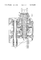
- FIG. 1 illustrates a cross-section view of the range transmission and the emergency brake on the drive shaft.
- the range transmission is driven by an engine and the main transmission and drives a differential.
- FIG. 2 illustrates a partial cross-section view of the brake and range transmission in the low range position.
- FIG. 3 is a partial cross-section view of the range transmission and brake in the high speed range.
- FIG. 4 is a partial cross-section view of the drive shaft showing a portion of the range transmission and the vehicle brake.
- FIG. 5 is a side elevation view of FIG. 4 showing a portion of the range transmission and the vehicle brake.
- the engine 1 drives the main transmission 2 which in turn drives the quill shaft 3.
- the quill shaft 3 drives through a coupling 4 into the hollow shaft 5.
- the hollow shaft 5 is drivingly connected to gears 6 and 7 through mating splines.
- the gears 6 and 7 are the driving gears for the gearsets 8 and 9 of which the driven gears are 19 and 10.
- the hollow shaft 5 is rotatably carried in the bearing assemblies 11 and 12.
- Gears 19 and 10 are rotatably mounted on the drive shaft 13 which is rotatably supported in the bearing assemblies 14 and 15.
- Gears 19 and 10 are formed with clutch teeth 16 and 17 which selectively clutch the gears to the drive shaft 13 through the clutch collar 18.
- the clutch collar 18 is carried on a clutch sleeve 109 through mating spline connection 20.
- the clutch sleeve is reciprocally carried on the drive shaft through a mating spline connection 21.
- Clutch collar 18 is formed with an annular recess 22 which carries a shifting fork 23.
- the external periphery of the clutch collar 18 is also formed with an axial spline 24 which engage a mating spline on the brake disks 25 and 26. Accordingly, the clutch collar 18 can be retained in the neutral position as shown in FIG. 1 or reciprocated to the low speed range and high speed range as shown in FIGS. 2 and 3, respectively.
- the drive shaft 13 is integral with the pinion gear 27 which drives into the differential 28 driving the rear wheels of the vehicle.
- the shifter fork 23 is shifted axially by the shaft 29 to reciprocate the clutch collar 18 to shift the range transmission.
- the caliper brake is manually operated through the brake lever 30 which rotates the shaft 31 and the cam 32.
- the cam 32 biases the pressure plate 33 against the brake disk 25 which in turn compresses the brake shoe 34 between the brake disks 25 and 26 and disk 26 against the reaction plate 35.
- Counterrotation of the cam 32 releases the brake and allows it to return to the disengaged or retracted position.
- Shifting of the shifter fork 23 reciprocates the sleeve clutch collar 18 to selectively engage clutch teeth 16 or 17 as the clutch collar shifts the range transmission. The operation of the device will be described in the following paragraphs.
- the engine 1 When the engine 1 is running, it drives the transmission 2 which is selectively shifted through a plurality of speed ranges.
- the drive from the transmission 2 is through the quill shaft 3 and the hollow shaft 5.
- the hollow shaft 5 carries the gears 6 and 7 of the gearsets 8 and 9.
- the gearsets 8 and 9 selectively drive the drive shaft 13.
- the range transmission 40 is provided with a clutch collar 18 which can be selectively reciprocated by the shifting fork 23.
- the range transmission can be shifted between the low speed range as shown in FIG. 2, the neutral position as shown in FIG. 1 and the high speed position as shown in FIG. 3.
- the parking brake or emergency brake 41 is also formed on the clutch collar 18.
- the brake disks 25 and 26 are connected through a spline connection to the clutch collar 18.
- the brake 41 is operated through the cam 32 to selectively engage and disengage the brake disks 25 and 26 which brake the rotation of the drive shaft 13.
- Emergency brake 41 is operated by the control lever 30 which selectively rotates and counterrotates the cam 32 to engage or disengage the brake.
- the drive shaft 13 drives through the pinion 27 which drives the ring gear 28 of the differential which in turn drives the drive wheels. Accordingly, if the drive shaft is locked, this in turn locks the drive wheels and provides a parking brake for the vehicle.
Landscapes
- Engineering & Computer Science (AREA)
- Transportation (AREA)
- Mechanical Engineering (AREA)
- Chemical & Material Sciences (AREA)
- Combustion & Propulsion (AREA)
- Braking Arrangements (AREA)
Abstract
Description
Claims (10)
Priority Applications (1)
| Application Number | Priority Date | Filing Date | Title |
|---|---|---|---|
| US06/331,537 US4475638A (en) | 1981-12-17 | 1981-12-17 | Transmission brake and clutch |
Applications Claiming Priority (1)
| Application Number | Priority Date | Filing Date | Title |
|---|---|---|---|
| US06/331,537 US4475638A (en) | 1981-12-17 | 1981-12-17 | Transmission brake and clutch |
Publications (1)
| Publication Number | Publication Date |
|---|---|
| US4475638A true US4475638A (en) | 1984-10-09 |
Family
ID=23294374
Family Applications (1)
| Application Number | Title | Priority Date | Filing Date |
|---|---|---|---|
| US06/331,537 Expired - Fee Related US4475638A (en) | 1981-12-17 | 1981-12-17 | Transmission brake and clutch |
Country Status (1)
| Country | Link |
|---|---|
| US (1) | US4475638A (en) |
Cited By (5)
| Publication number | Priority date | Publication date | Assignee | Title |
|---|---|---|---|---|
| US4577524A (en) * | 1982-06-18 | 1986-03-25 | Caterpillar Tractor Co. | Vehicle transfer gear and drive line brake mechanism |
| US6332523B1 (en) | 2000-03-22 | 2001-12-25 | Spicer Technologies, Inc. | Axle assembly parking brake mechanism |
| US20070006673A1 (en) * | 2005-07-11 | 2007-01-11 | Team Industries, Inc. | Transmission |
| US20120291577A1 (en) * | 2011-05-17 | 2012-11-22 | Hicks Jason L | Transmission assembly including brake |
| WO2016051284A1 (en) * | 2014-10-03 | 2016-04-07 | Umm Al-Qura University | Drive shaft mounted emergency brake |
Citations (5)
| Publication number | Priority date | Publication date | Assignee | Title |
|---|---|---|---|---|
| US3132538A (en) * | 1961-07-17 | 1964-05-12 | Berliet Automobiles | Two-speed gear box having planet gear train |
| US3321054A (en) * | 1965-02-03 | 1967-05-23 | Caterpillar Tractor Co | Transmission lock |
| US3498425A (en) * | 1968-11-27 | 1970-03-03 | Yamaha Motor Co Ltd | Chain transmission with caliper brake |
| US4148382A (en) * | 1976-10-01 | 1979-04-10 | Kanzaki Kokyukoki Mfg. Co., Ltd. | Vehicle power transmission with brake |
| US4211313A (en) * | 1977-12-22 | 1980-07-08 | Allis-Chalmers Corporation | Transmission brake with lubricating and cooling means |
-
1981
- 1981-12-17 US US06/331,537 patent/US4475638A/en not_active Expired - Fee Related
Patent Citations (5)
| Publication number | Priority date | Publication date | Assignee | Title |
|---|---|---|---|---|
| US3132538A (en) * | 1961-07-17 | 1964-05-12 | Berliet Automobiles | Two-speed gear box having planet gear train |
| US3321054A (en) * | 1965-02-03 | 1967-05-23 | Caterpillar Tractor Co | Transmission lock |
| US3498425A (en) * | 1968-11-27 | 1970-03-03 | Yamaha Motor Co Ltd | Chain transmission with caliper brake |
| US4148382A (en) * | 1976-10-01 | 1979-04-10 | Kanzaki Kokyukoki Mfg. Co., Ltd. | Vehicle power transmission with brake |
| US4211313A (en) * | 1977-12-22 | 1980-07-08 | Allis-Chalmers Corporation | Transmission brake with lubricating and cooling means |
Cited By (7)
| Publication number | Priority date | Publication date | Assignee | Title |
|---|---|---|---|---|
| US4577524A (en) * | 1982-06-18 | 1986-03-25 | Caterpillar Tractor Co. | Vehicle transfer gear and drive line brake mechanism |
| US6332523B1 (en) | 2000-03-22 | 2001-12-25 | Spicer Technologies, Inc. | Axle assembly parking brake mechanism |
| US20070006673A1 (en) * | 2005-07-11 | 2007-01-11 | Team Industries, Inc. | Transmission |
| US7581467B2 (en) * | 2005-07-11 | 2009-09-01 | Team Industries, Inc. | Transmission |
| US20120291577A1 (en) * | 2011-05-17 | 2012-11-22 | Hicks Jason L | Transmission assembly including brake |
| US8910546B2 (en) * | 2011-05-17 | 2014-12-16 | Jason L. Hicks | Transmission assembly including brake |
| WO2016051284A1 (en) * | 2014-10-03 | 2016-04-07 | Umm Al-Qura University | Drive shaft mounted emergency brake |
Similar Documents
| Publication | Publication Date | Title |
|---|---|---|
| US9951851B2 (en) | Multi ratio drive | |
| EP0207910B1 (en) | Motor vehicle gearbox | |
| EP1544508B1 (en) | Multi-speed transmission | |
| US20100267508A1 (en) | Direct drive electric shift two speed planetary gearbox | |
| US4318305A (en) | Synchronized transmission | |
| US3673890A (en) | Auxiliary transmission | |
| US3827520A (en) | Clutch means for a 4 {33 {11 4 drive transfer vehicle | |
| US5711740A (en) | Mechanical clutch for planetary-type gear reduction unit | |
| US4635495A (en) | Multi-speed reversible power transmission | |
| CA2028143A1 (en) | Two-speed planetary gear mechanism | |
| US4798103A (en) | Automatic transmission with add-on overdrive | |
| CA1108887A (en) | Transmission having a two-speed planetary gear set | |
| US4799399A (en) | Manually controlled multiple speed ratio transmission | |
| GB2097078A (en) | Parking lock arrangement for continuously variable v-belt transmission | |
| US4627301A (en) | Change speed transmission | |
| US6202499B1 (en) | Automotive transmission | |
| US5076111A (en) | Modular drive axle having a three-speed transmission | |
| US5799536A (en) | Motor vehicle gearbox | |
| US4475638A (en) | Transmission brake and clutch | |
| US2683997A (en) | Change-speed gear with two freewheeling devices | |
| HU214728B (en) | Thrust disc arrangement for transfering axial pressure in vehicle gear-box | |
| CA1176081A (en) | Change-speed apparatus in a tractor | |
| JPS60159463A (en) | Power extractor | |
| US3593596A (en) | Power transmission mechanism | |
| US5389047A (en) | Automotive automatic transmission |
Legal Events
| Date | Code | Title | Description |
|---|---|---|---|
| AS | Assignment |
Owner name: ALLIS-CHALMERS CORPORATION, BOX 512 MILWAUKEE, WI Free format text: ASSIGNMENT OF ASSIGNORS INTEREST.;ASSIGNOR:MC CORMICK, STEPHEN J.;REEL/FRAME:003969/0225 Effective date: 19811208 |
|
| AS | Assignment |
Owner name: CONNECTICUT NATIONAL BANK THE, A NATIONAL BANKING Free format text: SECURITY INTEREST;ASSIGNOR:ALLIS-CHALMERS CORPORATION A DE CORP.;REEL/FRAME:004149/0001 Effective date: 19830329 Owner name: WOODS KATHLEEN D., AS TRUSTEE Free format text: SECURITY INTEREST;ASSIGNOR:ALLIS-CHALMERS CORPORATION A DE CORP.;REEL/FRAME:004149/0001 Effective date: 19830329 |
|
| AS | Assignment |
Owner name: WOODS, KATHLEEN D., AS TRUSTEES Free format text: SECURITY INTEREST;ASSIGNOR:ALLIS-CHALMERS CORPORATION;REEL/FRAME:004348/0078 Effective date: 19841214 Owner name: CONNECTICUT NATIONAL BANK, A NATIONAL BAMKING ASSC Free format text: SECURITY INTEREST;ASSIGNOR:ALLIS-CHALMERS CORPORATION;REEL/FRAME:004348/0078 Effective date: 19841214 |
|
| AS | Assignment |
Owner name: DEUTZ-ALLIS CORPORATION BOX 933, MILWAUKEE, WI 53 Free format text: ASSIGNMENT OF ASSIGNORS INTEREST.;ASSIGNOR:ALLIS-CHALMER CORPORATION A DE CORP;REEL/FRAME:004434/0722 Effective date: 19850627 |
|
| FPAY | Fee payment |
Year of fee payment: 4 |
|
| FEPP | Fee payment procedure |
Free format text: PAYOR NUMBER ASSIGNED (ORIGINAL EVENT CODE: ASPN); ENTITY STATUS OF PATENT OWNER: LARGE ENTITY |
|
| AS | Assignment |
Owner name: WHIRLPOOL FINANCIAL CORPORATION, A DE CORP., MICHI Free format text: SECURITY INTEREST;ASSIGNOR:DEUTZ-ALLIS CORPORATION;REEL/FRAME:005356/0744 Effective date: 19900621 |
|
| REMI | Maintenance fee reminder mailed | ||
| LAPS | Lapse for failure to pay maintenance fees | ||
| FP | Lapsed due to failure to pay maintenance fee |
Effective date: 19921011 |
|
| STCH | Information on status: patent discontinuation |
Free format text: PATENT EXPIRED DUE TO NONPAYMENT OF MAINTENANCE FEES UNDER 37 CFR 1.362 |