US4474331A - Recessed center vane for full cone nozzle - Google Patents
Recessed center vane for full cone nozzle Download PDFInfo
- Publication number
- US4474331A US4474331A US06/424,345 US42434582A US4474331A US 4474331 A US4474331 A US 4474331A US 42434582 A US42434582 A US 42434582A US 4474331 A US4474331 A US 4474331A
- Authority
- US
- United States
- Prior art keywords
- vane
- diameter
- nozzle
- equal
- center
- Prior art date
- Legal status (The legal status is an assumption and is not a legal conclusion. Google has not performed a legal analysis and makes no representation as to the accuracy of the status listed.)
- Expired - Fee Related
Links
Images

Classifications
-
- B—PERFORMING OPERATIONS; TRANSPORTING
- B05—SPRAYING OR ATOMISING IN GENERAL; APPLYING FLUENT MATERIALS TO SURFACES, IN GENERAL
- B05B—SPRAYING APPARATUS; ATOMISING APPARATUS; NOZZLES
- B05B1/00—Nozzles, spray heads or other outlets, with or without auxiliary devices such as valves, heating means
- B05B1/34—Nozzles, spray heads or other outlets, with or without auxiliary devices such as valves, heating means designed to influence the nature of flow of the liquid or other fluent material, e.g. to produce swirl
- B05B1/3405—Nozzles, spray heads or other outlets, with or without auxiliary devices such as valves, heating means designed to influence the nature of flow of the liquid or other fluent material, e.g. to produce swirl to produce swirl
- B05B1/341—Nozzles, spray heads or other outlets, with or without auxiliary devices such as valves, heating means designed to influence the nature of flow of the liquid or other fluent material, e.g. to produce swirl to produce swirl before discharging the liquid or other fluent material, e.g. in a swirl chamber upstream the spray outlet
- B05B1/3421—Nozzles, spray heads or other outlets, with or without auxiliary devices such as valves, heating means designed to influence the nature of flow of the liquid or other fluent material, e.g. to produce swirl to produce swirl before discharging the liquid or other fluent material, e.g. in a swirl chamber upstream the spray outlet with channels emerging substantially tangentially in the swirl chamber
- B05B1/3431—Nozzles, spray heads or other outlets, with or without auxiliary devices such as valves, heating means designed to influence the nature of flow of the liquid or other fluent material, e.g. to produce swirl to produce swirl before discharging the liquid or other fluent material, e.g. in a swirl chamber upstream the spray outlet with channels emerging substantially tangentially in the swirl chamber the channels being formed at the interface of cooperating elements, e.g. by means of grooves
- B05B1/3447—Nozzles, spray heads or other outlets, with or without auxiliary devices such as valves, heating means designed to influence the nature of flow of the liquid or other fluent material, e.g. to produce swirl to produce swirl before discharging the liquid or other fluent material, e.g. in a swirl chamber upstream the spray outlet with channels emerging substantially tangentially in the swirl chamber the channels being formed at the interface of cooperating elements, e.g. by means of grooves the interface being a cylinder having the same axis as the outlet
Definitions
- This invention relates to a recessed center vane of a straight-through solid cone spray nozzle.
- Straight-through spray nozzles with a solid cone spray are old and well known in the art as shown, for example, in co-pending U.S. patent application Ser. No. 322,169 filed Nov. 17, 1981 and issued on Sept. 27, 1983 as U.S. Pat. No. 4,406,407 entitled "High Flow Low Energy Solid Jet Nozzle” and assigned to the assignee of the present invention.
- Straight-through solid cone nozzles are also commercially available as, for example, by Wm. Steinen Mfg. Co. of Parsippany, N.J., the assignee of the present application.
- Solid cone nozzles commonly comprise a straight-through nozzle body having an input chamber which is connected to a fluid-connecting conduit of given diameter and flow capacity for fluids at a given pressure.
- a center vane is placed in the input chamber of the nozzle body and communicates between the input section and an axial discharge orifice of the nozzle body.
- the center vane commonly is provided with a plurality of slots which differ in number, angular configuration and size depending upon the desired end use. It is desirable to design the unit so that the fluid flow per unit of time at any unit area across the cone is as uniform as possible relative to other unit area in the same plane across the cone and thus maintain a solid spray cone.
- the vane for the spray nozzle was custom-made for a particular application to obtain a solid spray cone under given conditions of input pipe size, input pressure and volumetric fluid flow. It was not possible to simply change the scale of a given vane design when going from one input pipe size to another or from one input pressure to another because the resulting spray pattern would no longer be uniform and generally would become hollow or otherwise unsuitable. Thus a new vane design was required for each set of new pressure, volumetric flow and pipe diameter parameters. These vane designs are time-consuming since they are generally reached only after considerable trial and error methods and the cost of the resulting nozzle is substantially increased.
- Parameters of the vane design which can be changed include the vane thickness, changes in the number of slots or channel openings and their location, changes in the angular relationship of the slot to the axis of the vane, changes in the cross-sectional geometry of the slot or channel openings through the vane and changes in the depth of the vane recess.
- the vane design would be commonly modified by increasing the number of slots through the vane and/or by increasing slot width. Care had to be taken, however, since, if the slots became too wide or too numerous, fluid distribution over the area of the spray cone was poor.
- This invention relates to full cone spray nozzles having substantially even distribution of the liquid throughout the entire cross-sectional spray pattern, as contrasted with hollow cone sprays where no liquid is present in the center portion of the spray.
- full cone spray nozzles are well known in the art, and are comprised of a nozzle body with an internal chamber having an input end into which liquid can be introduced and a reduced diameter axial discharge orifice at the other end of the chamber.
- a center vane means is provided within the chamber and spaced from the discharge orifice so that liquid passing through the chamber has a swirling or rotative motion applied thereto coupled with a controlled amount of turbulence.
- the liquid assumes a conical form and should have uniform distribution of the particles of fluid throughout the transverse cross-sectional area of the spray.
- full cone spray nozzles In full cone spray nozzles, the capacity is determined by the cross-sectional area of discharge orifice and the operating pressure. In order to achieve uniformity of particle distribution in the spray, the dimensional relationships between the orifice of the center vane and the internal chamber constitute variables that contribute and interact in attaining the desired results.
- Full cone spray nozzles have a wide field of usefulness and there are large numbers of nozzles that are commercially available to provide nozzles having the desired combination of capacity, spray angle and pressure to satisfy the majority of design situations. There may be at least 40 different nozzle sizes at 40 pounds per square inch liquid pressure to provide capacities of from one (1) gallon per minute to 15,000 gallons per minute with spray angles ranging between 20° and 140°.
- a novel center vane geometry has been produced which has been found to form a uniform solid cone spray for a wide range of pipe diameters, volumetric flow and input fluid pressures.
- the vane geometry of the invention applies to pipes of any diameter from one-eighth (0.125) inch to 24 inches employing input pressures of from 1 p.s.i. to 150 p.s.i. and requiring a flow of between 1 to 15,000 gallons per minute.
- the number of channel slots employed for the center vane is three (3). Each slot is spaced 120° from the other and has a generally rectangular cross-section including a flat bottom.
- the slots are placed at an angle to the axis of the vane.
- the angle could be one-half the desired exit or spray angle, where the slot angle is measured between the center line axis of the vane and a line extending along the center of the bottom of each slot.
- the 45° angle for the most popular spray angle of 90°, could be retained and an adjustment in the exit flare of the nozzle could be made to adjust for larger or smaller spray angles.
- Each slot has a width equal to one-fourth (0.25) of the nozzle diameter and a depth equal to nozzle diameter divided by the number of slots, i.e. three (3).
- the vane length, measured along the vane axis, is equal to one-half (0.5) the nozzle diameter and the vane diameter is equal to the pipe or nozzle diameter.
- the vane is spaced from the orifice by a distance equal to the diameter of the vane or diameter of the nozzle.
- the total inlet opening area of the vane is substantially less than the outlet opening area of the vane. This is accomplished by having a recess cut into the outlet end of the vane. This recess permits the creation of a solid cone spray and by properly relating the depth of the recess in the vane to the orifice diameter, it is possible to have a substantially uniform distribution of particles in the full cone spray.
- the novel combination of the nozzle and recessed center vane produces a swirling motion or controlled turbulence of fluid as it flows through the vane and nozzle body and before entering the discharge orifice.
- the spray forms a solid cone having a very uniform distribution throughout the transverse cross-sectional area of the cone.
- the vane diameter is proportionally changed and the above geometrical relationships for the channel or slot openings through the vane are maintained and the same desired uniform solid spray cone will still be produced.
- the novel solid cone configuration of uniform distribution is maintained.
- the novel vane structure of the invention can be made from any desired material including metals and plastics.
- a typical metal is steel and a typical plastic is polyvinyl chloride.
- the conduit to which the nozzle is connected can be of any desired material and may be of metal such as steel or plastic such as polyvinyl chloride.
- Another object is to ensure equal distribution of liquid in a full cone by having a novel recessed center vane.
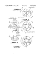
- FIG. 1 is a plan view of a nozzle body which may employ the recessed center vane of the present invention.
- FIG. 2 is a cross-sectional view of FIG. 1 taken across the section lines 2--2 in FIG. 1.
- FIG. 3 is a cross-sectional view similar to that of FIG. 2 but shows a recessed center vane in the nozzle body constructed in accordance with the principles of the present invention.
- FIG. 4 is an elevational view of the input face of the center vane of the present invention.
- FIG. 5 is a side view of FIG. 4 as seen from the line 5--5 in FIG. 4.
- FIG. 6 is another side view of FIG. 4 as seen from the lines 6--6 in FIG. 4.
- FIG. 7 is an elevation view of the output face of the center vane and is the view as seen from lines 7--7 of FIG. 6.
- FIG. 8 is a partial cross-sectional view taken across the section lines 8--8 in FIG. 6, and illustrates the square shape of a slot or channel.
- FIGS. 1, 2 and 3 there is shown a typical spray nozzle body 20 which may be a cast iron member which has been appropriately machined to contain an output orifice 21 in it output end and pipe-receiving threads 22 in its inlet end.
- the pipe-receiving threads 22 are adapted to receive any suitable fluid conduit which has male threads to cooperate with threads 22.
- the conduits received by threads 22 may be of metal or plastic.
- Body 20 may have a tapped opening 24 therein which receives a set screw 25 which is used to fix a center vane 30 in place and against locating shoulder 31. If desired, however, the vane 30 can be force-fit into body 20 to eliminate set screw 25.
- the structure of center vane 30 is the subject of this invention and will be described in connection with FIGS. 4 through 8.
- the purpose of the assembly is to produce a solid spray cone as schematically shown by the dotted lines in FIG. 3.
- This spray cone is intended to have an equal distribution over its entire cross-sectional area which is relatively uniform.
- the center vane 30, which causes a twirling and turbulent action of the fluid which passes through openings in the vane 30, has a very substantial influence on the uniformity of distribution of spray over the area of the cone. In the past, this uniformity was usually disturbed when there were changes in the volumetric flow of fluid into body 20 and through the vane 30 and was also disturbed by changes in the pressure of the fluid at the input side of body 20.
- the novel vane of the invention has been found to produce a very uniform distribution of spray throughout the cone angle within ranges, for example, of 20 solid degrees to 140 solid degrees of cone angle; for pressure variations of 1 p.s.i. to 150 p.s.i. of the input fluid; and mass flows, depending on orifice and pipe sizes and pressures, for example, 1 gallon per minute to 15,000 gallons per minute at 10 p.s.i.; and for input pipe diameters of 1/8 inch to 24 inches. Note that larger nozzles would be used at the lower pressures of the above ranges.
- the novel center vane 30 shown in FIGS. 4, 5, 6 and 7 consists of a main body which can be of steel or other metal, ceramic, silicon plastics, such as polyvinyl chloride and the like.
- the outer diameter of the center vane 30 will be closely matched to the pipe or nozzle diameter, which is the inner diameter of the body 20 within which it must fit, as shown in FIG. 3.
- the center vane 30 is provided with three skewed channels or slots which are rotationally symmetric around the vane axis with respect to one another. Channels or slots are located 120° from one another around the axis of vane 30.
- center vane 30 as seen respectively in FIGS. 4 and 7, are parallel to each other, as seen in FIGS. 5 and 6.
- a slot geometry was selected which employs the generally rectangular cross-section as seen in FIG. 8.
- the width of the slots is made equal to one-fourth (0.25) times the diameter of the center vane or nozzle diameter. This slot width is shown in FIGS. 6 and 8 where it can be seen that the slots have a flat square bottom.
- the slot depth as measured at the input face of FIG. 4, is one-third (0.33) times the nozzle diameter.
- the total vane length shown in FIGS. 3, 5 and 6 has been found preferably to be one-half (0.5) times the pipe or nozzle diameter.
- any of the slots relative to the vane axis is equal to one-half (0.5) times the desired spray angle, as seen in FIG. 3.
- a spray angle of 90° would have a slot angle of 45°.
- the center vane recess provides the means whereby the fluid can be properly distributed so that a solid spray cone will result. It has been found that the recess is a very critical dimension and if not properly calculated can result in an uneven distribution of fluid particles in the cross-section of the cone spray. It has been found that if the orifice diameter is equal to or greater than one-half (0.5) the nozzle diameter, then the vane recess depth should be equal to one-fourth (0.25) the nozzle diameter or pipe diameter. However, if the orifice diameter is less than half the nozzle diameter, too much fluid from the slots is moved into the center of the recess. Hence, it is necessary to reduce the depth of the recess under these conditions. This is achieved by following the following relation. If the orifice diameter is less than one-half (0.5) the nozzle diameter or pipe diameter, then the vane recess depth should vary as the square of the orifice diameter divided by the pipe or nozzle diameter.
- center vane 30 can be either plastic or metal or other materials.
- the conduit connected to the threads 22 is also of metal, its inner diameter closely matches the inner diameter of housing 20 and thus the outer diameter of vane 30.
- the plastic pipe inner diameter may be slightly smaller than the outer diameter of vane 30 so that there is a small flow discontinuity at the point where the conduit ends and the vane surface begins.
- vane, nozzle body and conduit or pipe are all made of plastic, there is no discontinuity.
- V DIAM center vane diameter
- V LENGTH vane length
- Each vane is designed according to a basic formula that bears a relation to the pipe size and orifice diameter. We have found that we can achieve optimum conditions for a uniform distribution of full cone spray by providing the center vane with three slots that are spaced circumferentially from each other by 120° as seen in FIGS. 4 and 7. Each slot is cut at an angle to the axis of the vane which is one-half the desired spray angle. The depth of the slot is equal to one-third of pipe size. The following relations will hold true.
- VR DEPTH is equal to 0.25 P DIAM. This relation of VR DEPTH being one-fourth the pipe size works well when the size of the O DIAM is equal to or greater than 0.5 P DIAM.
- the dimensions of the VR DEPTH are critical to the distribution of the fluid particles. If the VR DEPTH were as large as 0.25 of the P DIAM when the O DIAM is less than 0.5 P DIAM, then there is too much fluid in the center of the stream and, hence, one does not obtain a uniform distribution full cone spray. That is, when the O DIAM is half or more of the N DIAM and the center vane is designed so that the VR DEPTH is one-fourth (0.25) of the N DIAM, then there is a good distribution of fluid particles so that a uniform distribution full cone spray will result.
- VR DEPTH should be less than one-fourth the P DIAM, i.e. O DIAM ⁇ 0.5 P DIAM, then VR DEPTH ⁇ 0.25 O DIAM.
- O DIAM is equal to or greater than one-half the P DIAM
- the novel design of the present invention permits the use of the same geometry for a wide range of pipe sizes and for a wide range of pressures and volumetric flows.
- a table showing the parameters of a vane design for pipe sizes varying from 1 inch internal diameter to 4 inches internal diameter. Note that the vane can be used in pipes smaller than 1 inch internal diameter and larger than 4 inches internal diameter while retaining the solid spray cone. The following table gives, in inches, the various parameters.
- typical dimension relations with the present invention would be as follows:
Landscapes
- Nozzles (AREA)
Abstract
Description
______________________________________
                              CONDITION AT
PIPE SIZE
         O DIAM    VR DEPTH   CENTER OF CONE
______________________________________
1.00     0.25      0.25       too much fluid
1.00     0.50      0.25       correct amount
1.00     0.75      0.25       correct amount
______________________________________
______________________________________
PIPE SIZE
         O DIAM     VR DEPTH    FULL cone
______________________________________
1.00     0.25       0.0625      uniform distri-
                                bution
1.00     0.50       0.250       uniform distri-
                                bution
1.00     0.75       0.250       uniform distri-
                                bution
______________________________________
__________________________________________________________________________
                      VANE VANE
       VANE DIAM
                ORIFICE
                      RECESS
                           RECESS
                                SPRAY
                                     VANE
PSI
   GMP NOZZLE DIAM
                DIAM  DIAM DEPTH
                                ANGLE
                                     LENGTH
__________________________________________________________________________
40 10  1.0      0.25   0.5 .063 55   0.5
40 to  1.0      0.50  0.5  .250 to   0.5
40 25  1.0      0.75  0.5  .250 95   0.5
40 15 to
       1.25     0.313 0.625
                           0.078
                                55 to
                                     0.625
40 45  1.25     0.625 0.625
                           0.313
                                90   0.625
40 20 to
       1.5      0.375 0.75 0.094
                                52 to
                                     0.75
40 70  1.5      0.75  0.75 0.375
                                90   0.75
40 40  2        0.375 1.0  0.070
                                50   1.0
40 to  2        0.50  1.0  0.125
                                to   1.0
40 140 2        1.00  1.0  0.500
                                97   1.0
40 60 to
       2.5      0.625 1.25 0.156
                                50 to
                                     1.25
40 210 2.5      1.250 1.25 0.625
                                85   1.25
40 100 3.0      0.50  1.5  0.083
                                45   1.5
40 to  3.0      0.75  1.5  0.188
                                to   1.5
40 280 3.0      1.50  1.5  0.750
                                90   1.5
40 365 4.0      0.75  2.0  0.141
                                75   2.0
40 to  4.0      1.0   2.0  0.250
                                to   2.0
40 485 4.0      2.0   2.0  1.000
                                80   2.0
__________________________________________________________________________
Claims (14)
Priority Applications (1)
| Application Number | Priority Date | Filing Date | Title |
|---|---|---|---|
| US06/424,345 US4474331A (en) | 1982-09-27 | 1982-09-27 | Recessed center vane for full cone nozzle |
Applications Claiming Priority (1)
| Application Number | Priority Date | Filing Date | Title |
|---|---|---|---|
| US06/424,345 US4474331A (en) | 1982-09-27 | 1982-09-27 | Recessed center vane for full cone nozzle |
Publications (1)
| Publication Number | Publication Date |
|---|---|
| US4474331A true US4474331A (en) | 1984-10-02 |
Family
ID=23682286
Family Applications (1)
| Application Number | Title | Priority Date | Filing Date |
|---|---|---|---|
| US06/424,345 Expired - Fee Related US4474331A (en) | 1982-09-27 | 1982-09-27 | Recessed center vane for full cone nozzle |
Country Status (1)
| Country | Link |
|---|---|
| US (1) | US4474331A (en) |
Cited By (17)
| Publication number | Priority date | Publication date | Assignee | Title |
|---|---|---|---|---|
| EP0245971A3 (en) * | 1986-04-18 | 1988-09-14 | Dickinson, Ben Wade Oakes, III | Hydraulic drilling apparatus and method |
| US4852668A (en) * | 1986-04-18 | 1989-08-01 | Ben Wade Oakes Dickinson, III | Hydraulic drilling apparatus and method |
| US5028006A (en) * | 1989-03-20 | 1991-07-02 | Recticel | Spray nozzle for spray gun for forming a polyurethane layer on a surface |
| EP0698416A1 (en) * | 1994-07-30 | 1996-02-28 | SPRAYING SYSTEMS DEUTSCHLAND GmbH & Co. KG | Spray nozzle for generating a hollow conical jet |
| WO1998037975A1 (en) * | 1997-02-28 | 1998-09-03 | Minna From Finland | Improved showers and shower cabinets |
| US6244524B1 (en) * | 1997-12-05 | 2001-06-12 | Saint-Gobain Glass France | Fuel injection burner |
| US6394366B1 (en) * | 2000-10-27 | 2002-05-28 | Spraying Systems Co. | Spray nozzle assembly |
| US6561440B1 (en) * | 2001-11-14 | 2003-05-13 | Spraying Systems Co. | Full cone spray nozzle for metal casting cooling system |
| US20070290073A1 (en) * | 2006-06-05 | 2007-12-20 | Spraying Systems Co. | Full cone air assisted spray nozzle for continuous metal casting cooling |
| US20090227185A1 (en) * | 2008-03-10 | 2009-09-10 | David Archibold Summers | Method and apparatus for jet-assisted drilling or cutting |
| US20110108292A1 (en) * | 2009-11-12 | 2011-05-12 | Daniel Glen Moyer | Inline plug flame arrestors |
| CN104010732A (en) * | 2012-12-25 | 2014-08-27 | 新日铁住金株式会社 | Full cone spray nozzle |
| JP2016123935A (en) * | 2015-01-05 | 2016-07-11 | スプレーイングシステムスジャパン株式会社 | Wide angle full cone spray nozzle |
| EP3108973A1 (en) * | 2015-06-22 | 2016-12-28 | Novartis Ag | Method and device for cleaning a molding surface of a reusable lens mold |
| US10000370B2 (en) | 2010-02-05 | 2018-06-19 | Ecowell, Llc | Container-less custom beverage vending invention |
| US10017372B2 (en) | 2010-02-05 | 2018-07-10 | Ecowell, Llc | Container-less custom beverage vending invention |
| US11426742B2 (en) * | 2020-01-28 | 2022-08-30 | Collins Engine Nozzles, Inc. | Spray nozzle |
Citations (6)
| Publication number | Priority date | Publication date | Assignee | Title |
|---|---|---|---|---|
| US1982840A (en) * | 1932-06-08 | 1934-12-04 | Ernest J Sweetland | Adjustable lawn sprinkling means |
| US2845304A (en) * | 1956-07-09 | 1958-07-29 | Dexter Ind Inc | Sprinkler head |
| US3275248A (en) * | 1964-08-07 | 1966-09-27 | Spraying Systems Co | Modified full cone nozzle |
| US3344558A (en) * | 1965-07-23 | 1967-10-03 | Wyatt S Kirkland | Sand blast nozzle |
| CA1050589A (en) * | 1977-02-04 | 1979-03-13 | Norman D. Bowen | Spray nozzle insert and method of making same |
| US4406407A (en) * | 1981-11-17 | 1983-09-27 | Wm. Steinen Mfg. Co. | High flow low energy solid cone spray nozzle |
-
1982
- 1982-09-27 US US06/424,345 patent/US4474331A/en not_active Expired - Fee Related
Patent Citations (6)
| Publication number | Priority date | Publication date | Assignee | Title |
|---|---|---|---|---|
| US1982840A (en) * | 1932-06-08 | 1934-12-04 | Ernest J Sweetland | Adjustable lawn sprinkling means |
| US2845304A (en) * | 1956-07-09 | 1958-07-29 | Dexter Ind Inc | Sprinkler head |
| US3275248A (en) * | 1964-08-07 | 1966-09-27 | Spraying Systems Co | Modified full cone nozzle |
| US3344558A (en) * | 1965-07-23 | 1967-10-03 | Wyatt S Kirkland | Sand blast nozzle |
| CA1050589A (en) * | 1977-02-04 | 1979-03-13 | Norman D. Bowen | Spray nozzle insert and method of making same |
| US4406407A (en) * | 1981-11-17 | 1983-09-27 | Wm. Steinen Mfg. Co. | High flow low energy solid cone spray nozzle |
Cited By (25)
| Publication number | Priority date | Publication date | Assignee | Title |
|---|---|---|---|---|
| EP0245971A3 (en) * | 1986-04-18 | 1988-09-14 | Dickinson, Ben Wade Oakes, III | Hydraulic drilling apparatus and method |
| US4852668A (en) * | 1986-04-18 | 1989-08-01 | Ben Wade Oakes Dickinson, III | Hydraulic drilling apparatus and method |
| AU597967B2 (en) * | 1986-04-18 | 1990-06-14 | Ben Wade Oakes Dickinson Iii | Hydraulic drilling apparatus and method |
| US5028006A (en) * | 1989-03-20 | 1991-07-02 | Recticel | Spray nozzle for spray gun for forming a polyurethane layer on a surface |
| EP0698416A1 (en) * | 1994-07-30 | 1996-02-28 | SPRAYING SYSTEMS DEUTSCHLAND GmbH & Co. KG | Spray nozzle for generating a hollow conical jet |
| FR2760182A1 (en) * | 1997-02-28 | 1998-09-04 | Minna From Finland | IMPROVED SHOWERS AND SHOWER ENCLOSURES |
| WO1998037975A1 (en) * | 1997-02-28 | 1998-09-03 | Minna From Finland | Improved showers and shower cabinets |
| US6244524B1 (en) * | 1997-12-05 | 2001-06-12 | Saint-Gobain Glass France | Fuel injection burner |
| US6394366B1 (en) * | 2000-10-27 | 2002-05-28 | Spraying Systems Co. | Spray nozzle assembly |
| US6561440B1 (en) * | 2001-11-14 | 2003-05-13 | Spraying Systems Co. | Full cone spray nozzle for metal casting cooling system |
| WO2003041866A1 (en) * | 2001-11-14 | 2003-05-22 | Spraying Systems Co. | Full cone spray nozzle for metal casting cooling sytsem |
| US7611080B2 (en) * | 2006-06-05 | 2009-11-03 | Spraying Systems Co. | Full cone air assisted spray nozzle for continuous metal casting cooling |
| US20070290073A1 (en) * | 2006-06-05 | 2007-12-20 | Spraying Systems Co. | Full cone air assisted spray nozzle for continuous metal casting cooling |
| US20090227185A1 (en) * | 2008-03-10 | 2009-09-10 | David Archibold Summers | Method and apparatus for jet-assisted drilling or cutting |
| US8257147B2 (en) | 2008-03-10 | 2012-09-04 | Regency Technologies, Llc | Method and apparatus for jet-assisted drilling or cutting |
| US20110108292A1 (en) * | 2009-11-12 | 2011-05-12 | Daniel Glen Moyer | Inline plug flame arrestors |
| US8960320B2 (en) * | 2009-11-12 | 2015-02-24 | Fisher Controls International Llc | Inline plug flame arrestors |
| US10000370B2 (en) | 2010-02-05 | 2018-06-19 | Ecowell, Llc | Container-less custom beverage vending invention |
| US10017372B2 (en) | 2010-02-05 | 2018-07-10 | Ecowell, Llc | Container-less custom beverage vending invention |
| CN104010732A (en) * | 2012-12-25 | 2014-08-27 | 新日铁住金株式会社 | Full cone spray nozzle |
| US9452438B2 (en) | 2012-12-25 | 2016-09-27 | Nippon Steel & Sumitomo Metal Corporation | Full cone spray nozzle |
| JP2016123935A (en) * | 2015-01-05 | 2016-07-11 | スプレーイングシステムスジャパン株式会社 | Wide angle full cone spray nozzle |
| EP3108973A1 (en) * | 2015-06-22 | 2016-12-28 | Novartis Ag | Method and device for cleaning a molding surface of a reusable lens mold |
| US10328612B2 (en) | 2015-06-22 | 2019-06-25 | Novartis Ag | Method and device for cleaning a molding surface of a reusable lens mold |
| US11426742B2 (en) * | 2020-01-28 | 2022-08-30 | Collins Engine Nozzles, Inc. | Spray nozzle |
Similar Documents
| Publication | Publication Date | Title |
|---|---|---|
| US4474331A (en) | Recessed center vane for full cone nozzle | |
| US4125226A (en) | Hollow cone nozzle for atomization of liquids | |
| US4134547A (en) | Jet pipe | |
| CA1311783C (en) | Spray nozzle design | |
| US3747851A (en) | Swirl air nozzle | |
| CN101495239B (en) | Full Cone Air Assist Nozzles for Continuous Metal Casting Cooling | |
| US3735778A (en) | Driving of fluids | |
| US3945574A (en) | Dual orifice spray nozzle using two swirl chambers | |
| US4456181A (en) | Gas liquid mixing nozzle | |
| US4406407A (en) | High flow low energy solid cone spray nozzle | |
| KR100668582B1 (en) | Fluid processing method and apparatus | |
| US3920187A (en) | Spray head | |
| CA1231235A (en) | Method and apparatus for forming a high velocity liquid abrasive jet | |
| US3640472A (en) | Liquid discharge nozzle having improved flow control means | |
| JP4141006B2 (en) | High pressure cleaning spray nozzle | |
| US5106022A (en) | Spray nozzles | |
| GB2075866A (en) | Shower fitting | |
| GB1603090A (en) | Jetting apparatus | |
| RU2369803C2 (en) | Liquid fuel spraying method and device for implementing thereof | |
| GB2157592A (en) | Flat jet spray nozzle for spraying plant protection agents | |
| US4055306A (en) | Liquid spray nozzle having a randomly directionally unstable discharge characteristic | |
| CN108160359B (en) | Nozzle device capable of realizing multiple spraying functions | |
| US4231524A (en) | Large flow nozzle | |
| CA2062404A1 (en) | Fluid vibrating type flowmeter | |
| EP3501664B1 (en) | Insert for hydraulic nozzles and hydraulic nozzle including said insert |
Legal Events
| Date | Code | Title | Description |
|---|---|---|---|
| AS | Assignment |
Owner name: WM.STEINEN MFG. CO. 29 EAST HALSEY RD.PARSIPPANY,N Free format text: ASSIGNMENT OF ASSIGNORS INTEREST.;ASSIGNORS:APREA, GEORGE F.;POHLE, WERNER P.;REEL/FRAME:004049/0602 Effective date: 19820920 Owner name: WM.STEINEN MFG. CO., NEW JERSEY Free format text: ASSIGNMENT OF ASSIGNORS INTEREST;ASSIGNORS:APREA, GEORGE F.;POHLE, WERNER P.;REEL/FRAME:004049/0602 Effective date: 19820920 |
|
| AS | Assignment |
Owner name: BETE FOG NOZZLE, INC., 324 WELLS STREET, BOX 311, Free format text: ASSIGNMENT OF ASSIGNORS INTEREST.;ASSIGNOR:WM. STEINER MFG. CO., A CORP OF N.J.;REEL/FRAME:004553/0134 Effective date: 19860522 Owner name: BETE FOG NOZZLE, INC., MASSACHUSETTS Free format text: ASSIGNMENT OF ASSIGNORS INTEREST;ASSIGNOR:WM. STEINER MFG. CO., A CORP OF N.J.;REEL/FRAME:004553/0134 Effective date: 19860522 |
|
| REMI | Maintenance fee reminder mailed | ||
| LAPS | Lapse for failure to pay maintenance fees | ||
| STCH | Information on status: patent discontinuation |
Free format text: PATENT EXPIRED DUE TO NONPAYMENT OF MAINTENANCE FEES UNDER 37 CFR 1.362 |
|
| FP | Lapsed due to failure to pay maintenance fee |
Effective date: 19881002 |
|
| AS | Assignment |
Owner name: SHAWMUT BANK OF FRANKLIN COUNTY, MASSACHUSETTS Free format text: SECURITY INTEREST;ASSIGNOR:BETE FOG NOZZLE, INC.;REEL/FRAME:005307/0605 Effective date: 19881116 |