US4467508A - Machine for cutting of armored or reinforced hoses - Google Patents
Machine for cutting of armored or reinforced hoses Download PDFInfo
- Publication number
- US4467508A US4467508A US06/431,076 US43107682A US4467508A US 4467508 A US4467508 A US 4467508A US 43107682 A US43107682 A US 43107682A US 4467508 A US4467508 A US 4467508A
- Authority
- US
- United States
- Prior art keywords
- hose
- cutting
- frame
- center member
- motor
- Prior art date
- Legal status (The legal status is an assumption and is not a legal conclusion. Google has not performed a legal analysis and makes no representation as to the accuracy of the status listed.)
- Expired - Fee Related
Links
- 238000005520 cutting process Methods 0.000 title claims abstract description 49
- 229910000831 Steel Inorganic materials 0.000 claims abstract description 7
- 239000010959 steel Substances 0.000 claims abstract description 7
- 230000005540 biological transmission Effects 0.000 claims abstract description 5
- 230000003014 reinforcing effect Effects 0.000 claims abstract description 4
- 239000012634 fragment Substances 0.000 abstract description 2
- 230000001105 regulatory effect Effects 0.000 abstract 1
- 238000012840 feeding operation Methods 0.000 description 2
- 239000002245 particle Substances 0.000 description 2
- 229910052751 metal Inorganic materials 0.000 description 1
- 239000002184 metal Substances 0.000 description 1
- 229910001092 metal group alloy Inorganic materials 0.000 description 1
- 150000002739 metals Chemical class 0.000 description 1
- 230000002787 reinforcement Effects 0.000 description 1
Images
Classifications
-
- B—PERFORMING OPERATIONS; TRANSPORTING
- B26—HAND CUTTING TOOLS; CUTTING; SEVERING
- B26D—CUTTING; DETAILS COMMON TO MACHINES FOR PERFORATING, PUNCHING, CUTTING-OUT, STAMPING-OUT OR SEVERING
- B26D3/00—Cutting work characterised by the nature of the cut made; Apparatus therefor
- B26D3/16—Cutting rods or tubes transversely
-
- B—PERFORMING OPERATIONS; TRANSPORTING
- B23—MACHINE TOOLS; METAL-WORKING NOT OTHERWISE PROVIDED FOR
- B23D—PLANING; SLOTTING; SHEARING; BROACHING; SAWING; FILING; SCRAPING; LIKE OPERATIONS FOR WORKING METAL BY REMOVING MATERIAL, NOT OTHERWISE PROVIDED FOR
- B23D21/00—Machines or devices for shearing or cutting tubes
- B23D21/04—Tube-severing machines with rotating tool-carrier
-
- B—PERFORMING OPERATIONS; TRANSPORTING
- B26—HAND CUTTING TOOLS; CUTTING; SEVERING
- B26D—CUTTING; DETAILS COMMON TO MACHINES FOR PERFORATING, PUNCHING, CUTTING-OUT, STAMPING-OUT OR SEVERING
- B26D11/00—Combinations of several similar cutting apparatus
-
- Y—GENERAL TAGGING OF NEW TECHNOLOGICAL DEVELOPMENTS; GENERAL TAGGING OF CROSS-SECTIONAL TECHNOLOGIES SPANNING OVER SEVERAL SECTIONS OF THE IPC; TECHNICAL SUBJECTS COVERED BY FORMER USPC CROSS-REFERENCE ART COLLECTIONS [XRACs] AND DIGESTS
- Y10—TECHNICAL SUBJECTS COVERED BY FORMER USPC
- Y10T—TECHNICAL SUBJECTS COVERED BY FORMER US CLASSIFICATION
- Y10T29/00—Metal working
- Y10T29/49—Method of mechanical manufacture
- Y10T29/49815—Disassembling
- Y10T29/49821—Disassembling by altering or destroying work part or connector
-
- Y—GENERAL TAGGING OF NEW TECHNOLOGICAL DEVELOPMENTS; GENERAL TAGGING OF CROSS-SECTIONAL TECHNOLOGIES SPANNING OVER SEVERAL SECTIONS OF THE IPC; TECHNICAL SUBJECTS COVERED BY FORMER USPC CROSS-REFERENCE ART COLLECTIONS [XRACs] AND DIGESTS
- Y10—TECHNICAL SUBJECTS COVERED BY FORMER USPC
- Y10T—TECHNICAL SUBJECTS COVERED BY FORMER US CLASSIFICATION
- Y10T29/00—Metal working
- Y10T29/51—Plural diverse manufacturing apparatus including means for metal shaping or assembling
- Y10T29/5147—Plural diverse manufacturing apparatus including means for metal shaping or assembling including composite tool
- Y10T29/5148—Plural diverse manufacturing apparatus including means for metal shaping or assembling including composite tool including severing means
-
- Y—GENERAL TAGGING OF NEW TECHNOLOGICAL DEVELOPMENTS; GENERAL TAGGING OF CROSS-SECTIONAL TECHNOLOGIES SPANNING OVER SEVERAL SECTIONS OF THE IPC; TECHNICAL SUBJECTS COVERED BY FORMER USPC CROSS-REFERENCE ART COLLECTIONS [XRACs] AND DIGESTS
- Y10—TECHNICAL SUBJECTS COVERED BY FORMER USPC
- Y10T—TECHNICAL SUBJECTS COVERED BY FORMER US CLASSIFICATION
- Y10T29/00—Metal working
- Y10T29/51—Plural diverse manufacturing apparatus including means for metal shaping or assembling
- Y10T29/5199—Work on tubes
Definitions
- the invention relates to a machine for cutting of armoured or reinforced hoses and particularly the invention relates to a machine for cutting or hoses, such as steel armoured or reinforced hydraulic hoses or hoses with an armouring or reinforcement of other metals or metal alloys.
- the cutting device or machine according the invention is not known from the earlier technics.
- a head object with the invention is to provide for a machine for cutting armoured or reinforced hoses and preferably steel armoured and reinforced hydraulic hoses in such a way, that fragments from the armouring or the reinforced layer are prevented to follow in to the hoses during a hose cutting operation.
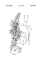
- a hose roll 1 is exchangeably mounted at a frame element 2. At cutting of preferably armoured or reinforced hydraulic hoses 3 the hose 3 is led over a roller 4.
- a slide 5 is arranged for feeding of appropriated lengths of armoured or reinforced hydraulic hoses 3 through the cutting machine.
- the slide 5 is arranged at a frame part 6 with steerings 6a for forward and backward movements.
- the slide 5 supports means 7 for holding of the hose 3 during its feeding forwards towards a cutting position.
- a rotable centre part 9 is arranged, which centre 9 is provided with a cog wheel transmission 10, which is rotable by means of a motor 11 via a cog wheel 12.
- the cog wheel transmission 10 is in its turn arranged to bring a frame part 13 in rotation, which frame part 13 supports necessary means for cutting a steel armoured or reinforced hydraulic hose 3.
- the frame part 13 is arranged with one towards the hose 3, which is intended to be cut, movable device 15, which includes a motor 16 arranged to bring a cutting wheel 17 in rotation.
- the cutting wheel movable sensor device 21 is arranged for sensing of the wearing state of the cutting wheel 17.
- the degree of the wearing state determines what distance the cutting wheel 17 must be moved towards the hose 3, which is intended to be cut. Furthermore the frame part 13 is arranged with steerings 14, which also support one towards the hose 3 movable fixing device 20, on which fixing device 20 a guillotine knife 26 is attached.
- a steel armoured hydraulic hose consists preferably of an inner gummed layer, armouring and an outer gummed layer. The cutting wheel 17 is used for cutting of the outer gummed layer and the armouring or reinforcing, while the guillotine is used for cutting of the inner gummed layer.
- the sensor device 21, which is arranged for determination of the wear of the cutting wheel 17, is moved or operated towards the wheel 17 by means of a motor 22 via a screw 23.
- the rotable cutting device 15 is moved towards and from the hose 3 during a cutting operation by means of a motor 24 via a screw 25.
- the movable guillotine 26 is guided via steerings 14 by means of a cylinder 27.
- the armoured hose 3 is passed through an exchangeable steering 28, which is moved towards and from the centre part 9 by means of a lever 29 arm and a cylinder 30.
- a feeding forward and out of the hose part 3 is effected by means of a slide 33, which is movable at a holder 35 via steerings 36.
- the holder 35 includes means 34 for holding of the hose 3 during the cutting and the out-feeding operation.
- the slide 33 is operated by means of a cylinder 37.
- a particle collector (not shown) is applicated or arranged in the area of the cutting wheel 17 to follow the rotation of the frame part 13. Because of that a decrease in pressure is achieved in the area of the cutting wheel 17 the particles, which are abraded during the cutting operation, will be suck up and collected.
- a transport path for cut parts of hoses 3 is arranged.
- the steering of the forward feeding, the cutting and the out-feeding operations is achieved by means of a micro processor, in which the diameter of the hose, the lengths of the hose parts and number of intended cuttings are programmed to provide for an automatic operation for cutting of especially steel armoured hydraulic hoses.
Landscapes
- Engineering & Computer Science (AREA)
- Mechanical Engineering (AREA)
- Life Sciences & Earth Sciences (AREA)
- Forests & Forestry (AREA)
- Grinding Of Cylindrical And Plane Surfaces (AREA)
- Processing And Handling Of Plastics And Other Materials For Molding In General (AREA)
- Lining Or Joining Of Plastics Or The Like (AREA)
- Finish Polishing, Edge Sharpening, And Grinding By Specific Grinding Devices (AREA)
- Nonmetal Cutting Devices (AREA)
Abstract
The invention relates to a machine for cutting of armoured or reinforced hose (3) and particularly steel armoured hydraulic hose (3). The machine is characterized by, that a frame part (13) is firmed attached to a rotable center part (9). The frame part (13) supports a movable cutting device (15), which includes a cutting wheel (17) and a motor (16). The position of the cutting device in relation to a hose, which is intended to be cut, is regulated by means of a motor (24) via a screw (25). Furthermore a movable sensor device or element (21) is arranged, which indicates the position and the wear of the cutting wheel (17) during a cutting operation. The frame part (13) also supports a movable guillotine knife (26). During a cutting operation the center part (9) and the frame part (13) are brought in rotation by means of a cog wheel transmission (10), a cog wheel (12) and a motor (11). Before a cutting operation an armoured or reinforced hose (3) is led through the center part (9) and the frame part (13), where the hose is fixed in a wished position by means of a chuck (31) and a holding device (34). An outer gummed layer and an inner armouring or reinforcing is cut by means of the cutting wheel (17). Lastly an inner gummed layer is cut by means of the guillotine knife (26).
The aim hereby is to provide for a cutting operation in such a way that fragments from the armouring or reinforcing are prevented from following in to the hose during the cutting operation.
Description
The invention relates to a machine for cutting of armoured or reinforced hoses and particularly the invention relates to a machine for cutting or hoses, such as steel armoured or reinforced hydraulic hoses or hoses with an armouring or reinforcement of other metals or metal alloys.
The cutting device or machine according the invention is not known from the earlier technics.
A head object with the invention is to provide for a machine for cutting armoured or reinforced hoses and preferably steel armoured and reinforced hydraulic hoses in such a way, that fragments from the armouring or the reinforced layer are prevented to follow in to the hoses during a hose cutting operation.
The machine according to the invention is characterized by the appended claims.
The machine according the invention will now be described in detail in the following with reference to the appended drawing, where one form of the machine according the invention is shown only as an example and not in the aim of limiting the scope of the invention.
A hose roll 1 is exchangeably mounted at a frame element 2. At cutting of preferably armoured or reinforced hydraulic hoses 3 the hose 3 is led over a roller 4. A slide 5 is arranged for feeding of appropriated lengths of armoured or reinforced hydraulic hoses 3 through the cutting machine. The slide 5 is arranged at a frame part 6 with steerings 6a for forward and backward movements. The slide 5 supports means 7 for holding of the hose 3 during its feeding forwards towards a cutting position.
In a frame part 8 a rotable centre part 9 is arranged, which centre 9 is provided with a cog wheel transmission 10, which is rotable by means of a motor 11 via a cog wheel 12. The cog wheel transmission 10 is in its turn arranged to bring a frame part 13 in rotation, which frame part 13 supports necessary means for cutting a steel armoured or reinforced hydraulic hose 3. The frame part 13 is arranged with one towards the hose 3, which is intended to be cut, movable device 15, which includes a motor 16 arranged to bring a cutting wheel 17 in rotation. Furthermore one towards the cutting wheel movable sensor device 21 is arranged for sensing of the wearing state of the cutting wheel 17. The degree of the wearing state determines what distance the cutting wheel 17 must be moved towards the hose 3, which is intended to be cut. Furthermore the frame part 13 is arranged with steerings 14, which also support one towards the hose 3 movable fixing device 20, on which fixing device 20 a guillotine knife 26 is attached. A steel armoured hydraulic hose consists preferably of an inner gummed layer, armouring and an outer gummed layer. The cutting wheel 17 is used for cutting of the outer gummed layer and the armouring or reinforcing, while the guillotine is used for cutting of the inner gummed layer.
The sensor device 21, which is arranged for determination of the wear of the cutting wheel 17, is moved or operated towards the wheel 17 by means of a motor 22 via a screw 23.
The rotable cutting device 15 is moved towards and from the hose 3 during a cutting operation by means of a motor 24 via a screw 25.
The movable guillotine 26 is guided via steerings 14 by means of a cylinder 27.
The armoured hose 3 is passed through an exchangeable steering 28, which is moved towards and from the centre part 9 by means of a lever 29 arm and a cylinder 30. An exchangeable chuck 31, which is preferably provided with a hollowed, conical and compressable cushion gum 32 in its front end, is provided for holding of the hose 3 during a cutting operation.
A feeding forward and out of the hose part 3 is effected by means of a slide 33, which is movable at a holder 35 via steerings 36. The holder 35 includes means 34 for holding of the hose 3 during the cutting and the out-feeding operation. The slide 33 is operated by means of a cylinder 37.
A particle collector (not shown) is applicated or arranged in the area of the cutting wheel 17 to follow the rotation of the frame part 13. Because of that a decrease in pressure is achieved in the area of the cutting wheel 17 the particles, which are abraded during the cutting operation, will be suck up and collected.
A transport path for cut parts of hoses 3 is arranged.
The steering of the forward feeding, the cutting and the out-feeding operations is achieved by means of a micro processor, in which the diameter of the hose, the lengths of the hose parts and number of intended cuttings are programmed to provide for an automatic operation for cutting of especially steel armoured hydraulic hoses.
The machine or device according the invention can be modified in several ways without departing the scope of the invention, which will be evident from the appended claims.
Claims (1)
1. A machine for cutting armored or reinforced hose, particularly a steel armored or reinforced hydraulic hose of the type including outer and inner layers having therebetween an armoring or reinforcing layer, said machine comprising:
a center member mounted for rotation and through which is passed a hose to be cut, said center member having fixed thereto a cog wheel transmission;
a frame fixed to said center member;
means for feeding the hose to be cut into said center member and said frame, said feeding means comprising a holder for holding the hose, a slide supporting said holder, a cylinder for moving said slide, said holder and the hose held by said holder into said center member and said frame to a cutting position, a guide through which passes the hose, and a cylinder for moving said guide toward and away from said center member;
means for cutting through the outer and armor layers of the hose during a cutting operation and comprising a grinding wheel mounted on said frame, a motor for rotating said grinding wheel, and first motor and screw means for moving said grinding wheel along the frame toward and away from the hose;
means for detecting the degree of wear of said grinding wheel and comprising a sensor and second motor and screw means for moving said sensor toward and away from said grinding wheel to sense the relative position of the periphery thereof;
means for cutting through the inner layer of the hose during a cutting operation and comprising a knife fixed to a support device, and a cylinder for moving said support device and said knife along guide rods on said frame toward and away from the hose;
means for rotating said center member and said frame, and thereby said grinding wheel and said knife, about said hose during a cutting operation, said rotating means comprising a cog wheel mounted for meshing engagement with said cog wheel transmission of said center member, and a motor for rotating said cog wheel;
means for holding the hose during the cutting operation and comprising a chuck extending through said center member and held by said guide;
means for removing a cut length of hose from said machine and comprising a gripper for holding the cut length of hose, a holder member supporting said gripper and cylinder means for moving said holder member, said gripper and the cut length of hose held thereby away from the frame; and
microprocessor means operatively connected for controlling automatically the operation of said feeding means, said outer and armor layer cutting means, said detecting means, said inner layer cutting means, said rotating means, and said removing means.
Applications Claiming Priority (2)
| Application Number | Priority Date | Filing Date | Title |
|---|---|---|---|
| SE8107876A SE440876B (en) | 1981-12-30 | 1981-12-30 | HOSE CUTTING MACHINE FOR CUTTING OF ARMED HOSE |
| SE8107876 | 1981-12-30 |
Publications (1)
| Publication Number | Publication Date |
|---|---|
| US4467508A true US4467508A (en) | 1984-08-28 |
Family
ID=20345406
Family Applications (1)
| Application Number | Title | Priority Date | Filing Date |
|---|---|---|---|
| US06/431,076 Expired - Fee Related US4467508A (en) | 1981-12-30 | 1982-09-30 | Machine for cutting of armored or reinforced hoses |
Country Status (5)
| Country | Link |
|---|---|
| US (1) | US4467508A (en) |
| EP (1) | EP0085284B1 (en) |
| JP (1) | JPS58126059A (en) |
| DE (1) | DE3274628D1 (en) |
| SE (1) | SE440876B (en) |
Cited By (21)
| Publication number | Priority date | Publication date | Assignee | Title |
|---|---|---|---|---|
| US4794684A (en) * | 1984-10-02 | 1989-01-03 | Lhomme, Sa | Method of and apparatus for cutting tubes |
| US4803771A (en) * | 1988-01-07 | 1989-02-14 | Lyons William G | Process for removing asbestos using taped troughs |
| US4953377A (en) * | 1986-12-19 | 1990-09-04 | Boxholm Produktion Ab | Method and apparatus for cutting and deburring tubes |
| EP0826467A1 (en) * | 1996-08-30 | 1998-03-04 | S.I.C.A. SERRANDE INFISSI CARPENTERIA ATTREZZATURA S.p.A. | Process, apparatus and tool for cutting a tubular bar |
| AU691071B2 (en) * | 1995-01-12 | 1998-05-07 | Axel Borje Pettersson | Method for cutting metal reinforced hoses, metal pipes and similar, and a device for utilization of the method |
| US6237204B1 (en) * | 1996-04-29 | 2001-05-29 | Slx Hydraulic Ab | Production of tubes |
| CN101623780B (en) * | 2009-07-30 | 2010-12-08 | 严光辉 | Full-automatic fixed-length cutting device of metallic hose |
| US20110154971A1 (en) * | 2009-12-28 | 2011-06-30 | Caterpillar, Inc. | Apparatus for Cutting Reinforced Hose with Reduced Interior Hose Contamination |
| CN102554959A (en) * | 2012-01-04 | 2012-07-11 | 潍坊现代塑胶有限公司 | Cut-to-length machine for plastic pipes |
| CN103962622A (en) * | 2014-05-16 | 2014-08-06 | 苏州塔可盛电子科技有限公司 | Novel cutting machine for positioning steel pipes |
| EP2853363A1 (en) * | 2013-09-27 | 2015-04-01 | Weil Engineering GmbH | Cutting or punching tool |
| CN105690446A (en) * | 2016-01-28 | 2016-06-22 | 上海交通大学 | Automatic cutting device for plastic hoses |
| CN106735515A (en) * | 2016-12-08 | 2017-05-31 | 无锡市彩云机械设备有限公司 | A kind of steel pipe cutting means |
| USD816742S1 (en) | 2016-08-05 | 2018-05-01 | Norwood Industries Inc. | Portable sawmill bandsaw housing |
| CN108000577A (en) * | 2017-11-30 | 2018-05-08 | 无锡佳欣电子产品有限公司 | A kind of two-tube cutter device |
| USD818013S1 (en) * | 2016-08-05 | 2018-05-15 | Norwood Industries Inc. | Portable sawmill lower carriage |
| USD831711S1 (en) | 2016-08-05 | 2018-10-23 | Norwood Industries, Inc. | Portable sawmill upper carriage front |
| USD834623S1 (en) | 2016-08-05 | 2018-11-27 | Norwood Industries Inc. | Portable sawmill upper carriage top and side |
| CN109571216A (en) * | 2018-11-22 | 2019-04-05 | 欧阳华 | Bar cropper is used in a kind of production of well cover for sewer |
| CN115464701A (en) * | 2022-09-13 | 2022-12-13 | 阿格思(苏州)流体动力科技有限公司 | Hose assembly and processing equipment thereof |
| US11541441B2 (en) * | 2018-03-27 | 2023-01-03 | Sandvik Materials Technology Deutschland Gmbh | Transport system for a wire or a sheet and method for delivering a wire or a sheet |
Families Citing this family (5)
| Publication number | Priority date | Publication date | Assignee | Title |
|---|---|---|---|---|
| FR2603824A1 (en) * | 1986-09-16 | 1988-03-18 | Menissier Pierre | Automatic clamping system fitted to the workpieces to be machined on a machine tool working with tools which revolve in a satellite trajectory around the said workpieces |
| RU2121413C1 (en) * | 1998-01-19 | 1998-11-10 | Салманов Михаил Михайлович | Method for parting finned tubular heat exchanger of different type metals and apparatus for performing the same |
| JP5890680B2 (en) * | 2011-12-27 | 2016-03-22 | 積水化学工業株式会社 | Flexible resin tube cutting device |
| JP6018816B2 (en) * | 2012-06-22 | 2016-11-02 | 株式会社ブリヂストン | Hose cutting device and hose cutting method |
| AT521694B1 (en) * | 2019-01-18 | 2020-04-15 | Bauernfeind Gilbert | Device for peeling and separating hydraulic hoses with several hose layers |
Citations (3)
| Publication number | Priority date | Publication date | Assignee | Title |
|---|---|---|---|---|
| US2604690A (en) * | 1946-08-14 | 1952-07-29 | Aetna Standard Eng Co | Cutoff machine |
| US3242566A (en) * | 1963-06-14 | 1966-03-29 | John J White | Tube cutting machine |
| US3400451A (en) * | 1967-01-23 | 1968-09-10 | Edward S. Pierce | Wire working apparatus |
Family Cites Families (6)
| Publication number | Priority date | Publication date | Assignee | Title |
|---|---|---|---|---|
| DE1242854B (en) * | 1959-12-17 | 1967-06-22 | Kupfer Asbest Co | Process for the production of sealing rings |
| US3149440A (en) * | 1960-03-01 | 1964-09-22 | Edward Charles Maguire | Work machines with tools in planetary and axial movement |
| BE792987A (en) * | 1971-12-20 | 1973-06-19 | Caterpillar Tractor Co | EQUIPMENT FOR PICKING HYDRAULIC HANDLES |
| US3768350A (en) * | 1972-03-21 | 1973-10-30 | Teledyne Inc | Apparatus for cutting workpieces |
| US3978747A (en) * | 1975-03-24 | 1976-09-07 | The Gates Rubber Company | Method and apparatus for severing reinforced elastomeric tubular articles |
| DE2906177A1 (en) * | 1979-02-17 | 1980-08-28 | Pkm Projekt | Automatic plastic tubing cutter - heats tubing on one pin and is moved out on coaxial pin after cutting |
-
1981
- 1981-12-30 SE SE8107876A patent/SE440876B/en not_active IP Right Cessation
-
1982
- 1982-09-30 US US06/431,076 patent/US4467508A/en not_active Expired - Fee Related
- 1982-10-26 EP EP82850211A patent/EP0085284B1/en not_active Expired
- 1982-10-26 DE DE8282850211T patent/DE3274628D1/en not_active Expired
- 1982-11-10 JP JP57196156A patent/JPS58126059A/en active Pending
Patent Citations (3)
| Publication number | Priority date | Publication date | Assignee | Title |
|---|---|---|---|---|
| US2604690A (en) * | 1946-08-14 | 1952-07-29 | Aetna Standard Eng Co | Cutoff machine |
| US3242566A (en) * | 1963-06-14 | 1966-03-29 | John J White | Tube cutting machine |
| US3400451A (en) * | 1967-01-23 | 1968-09-10 | Edward S. Pierce | Wire working apparatus |
Cited By (26)
| Publication number | Priority date | Publication date | Assignee | Title |
|---|---|---|---|---|
| US4794684A (en) * | 1984-10-02 | 1989-01-03 | Lhomme, Sa | Method of and apparatus for cutting tubes |
| US4953377A (en) * | 1986-12-19 | 1990-09-04 | Boxholm Produktion Ab | Method and apparatus for cutting and deburring tubes |
| US4803771A (en) * | 1988-01-07 | 1989-02-14 | Lyons William G | Process for removing asbestos using taped troughs |
| US6073526A (en) * | 1995-01-12 | 2000-06-13 | Pettersson; Axel Boerje | Method for cutting metal reinforced hoses, metal pipes and similar, and a device for utilization of the method |
| AU691071B2 (en) * | 1995-01-12 | 1998-05-07 | Axel Borje Pettersson | Method for cutting metal reinforced hoses, metal pipes and similar, and a device for utilization of the method |
| US6237204B1 (en) * | 1996-04-29 | 2001-05-29 | Slx Hydraulic Ab | Production of tubes |
| EP0826467A1 (en) * | 1996-08-30 | 1998-03-04 | S.I.C.A. SERRANDE INFISSI CARPENTERIA ATTREZZATURA S.p.A. | Process, apparatus and tool for cutting a tubular bar |
| US6009780A (en) * | 1996-08-30 | 2000-01-04 | Sica S.P.A. | Process, apparatus and tool for cutting a tubular bar |
| CN101623780B (en) * | 2009-07-30 | 2010-12-08 | 严光辉 | Full-automatic fixed-length cutting device of metallic hose |
| US20110154971A1 (en) * | 2009-12-28 | 2011-06-30 | Caterpillar, Inc. | Apparatus for Cutting Reinforced Hose with Reduced Interior Hose Contamination |
| WO2011090637A3 (en) * | 2009-12-28 | 2011-10-13 | Caterpillar Inc. | Apparatus for cutting reinforced hose with reduced interior hose contamination |
| CN102554959A (en) * | 2012-01-04 | 2012-07-11 | 潍坊现代塑胶有限公司 | Cut-to-length machine for plastic pipes |
| EP2853363A1 (en) * | 2013-09-27 | 2015-04-01 | Weil Engineering GmbH | Cutting or punching tool |
| CN103962622A (en) * | 2014-05-16 | 2014-08-06 | 苏州塔可盛电子科技有限公司 | Novel cutting machine for positioning steel pipes |
| CN105690446A (en) * | 2016-01-28 | 2016-06-22 | 上海交通大学 | Automatic cutting device for plastic hoses |
| CN105690446B (en) * | 2016-01-28 | 2017-12-19 | 上海交通大学 | Plastic flexible pipe automatic cutting device |
| USD816742S1 (en) | 2016-08-05 | 2018-05-01 | Norwood Industries Inc. | Portable sawmill bandsaw housing |
| USD818013S1 (en) * | 2016-08-05 | 2018-05-15 | Norwood Industries Inc. | Portable sawmill lower carriage |
| USD831711S1 (en) | 2016-08-05 | 2018-10-23 | Norwood Industries, Inc. | Portable sawmill upper carriage front |
| USD834623S1 (en) | 2016-08-05 | 2018-11-27 | Norwood Industries Inc. | Portable sawmill upper carriage top and side |
| CN106735515A (en) * | 2016-12-08 | 2017-05-31 | 无锡市彩云机械设备有限公司 | A kind of steel pipe cutting means |
| CN108000577A (en) * | 2017-11-30 | 2018-05-08 | 无锡佳欣电子产品有限公司 | A kind of two-tube cutter device |
| US11541441B2 (en) * | 2018-03-27 | 2023-01-03 | Sandvik Materials Technology Deutschland Gmbh | Transport system for a wire or a sheet and method for delivering a wire or a sheet |
| CN109571216A (en) * | 2018-11-22 | 2019-04-05 | 欧阳华 | Bar cropper is used in a kind of production of well cover for sewer |
| CN115464701A (en) * | 2022-09-13 | 2022-12-13 | 阿格思(苏州)流体动力科技有限公司 | Hose assembly and processing equipment thereof |
| CN115464701B (en) * | 2022-09-13 | 2023-09-29 | 阿格思(苏州)流体动力科技有限公司 | Hose assembly and processing equipment thereof |
Also Published As
| Publication number | Publication date |
|---|---|
| SE440876B (en) | 1985-08-26 |
| SE8107876L (en) | 1983-07-01 |
| EP0085284A1 (en) | 1983-08-10 |
| EP0085284B1 (en) | 1986-12-10 |
| DE3274628D1 (en) | 1987-01-22 |
| JPS58126059A (en) | 1983-07-27 |
Similar Documents
| Publication | Publication Date | Title |
|---|---|---|
| US4467508A (en) | Machine for cutting of armored or reinforced hoses | |
| US7147542B2 (en) | Centerless grinder | |
| KR930010587B1 (en) | Guide devices for wire or strip-shaped cutting electrodes on machine tools | |
| US6397900B1 (en) | Apparatus for shaping wire into wire products | |
| US4998455A (en) | Automatic lathe for machining work bars | |
| US3793708A (en) | Automatic cutting-tip replacing apparatus | |
| JPH0232126B2 (en) | ||
| US20240157455A1 (en) | Horizontal band saw machine | |
| JP2006075980A (en) | Wire cutting device in electric discharging machine, wire transporting system, and wire electrode cutting method | |
| HUE034056T2 (en) | Adjustment apparatus | |
| US5771765A (en) | Sawdust removing apparatus for saw machine | |
| JPS61209816A (en) | Pipe cutting machine | |
| FI76272C (en) | FOERFARANDE OCH ANORDNING FOER SLIPNING AEVEN AV SMAO ARBETSSTYCKEN. | |
| US5009136A (en) | Turning machine | |
| US4440533A (en) | Deburring tool | |
| US5293932A (en) | Apparatus for cutting off projections inside pipes | |
| US2976978A (en) | Device for feeding tapered rollers or the like into grinding devices | |
| US2384732A (en) | Feed mechanism | |
| JPS5953198A (en) | Method of cutting excessive rubber tube in rubber tube braiding work | |
| EP0838296B1 (en) | Sawing machine including a sawdust removing device | |
| JP4776255B2 (en) | Band saw machine | |
| CN211939395U (en) | Thread length adjusting and limiting mechanism of steel bar threading machine | |
| CA1109389A (en) | Flame cutter | |
| US4286446A (en) | Machine control apparatus | |
| EP2452779B1 (en) | Device for determining the feed rate of a finishing belt |
Legal Events
| Date | Code | Title | Description |
|---|---|---|---|
| FEPP | Fee payment procedure |
Free format text: PAYOR NUMBER ASSIGNED (ORIGINAL EVENT CODE: ASPN); ENTITY STATUS OF PATENT OWNER: SMALL ENTITY |
|
| FPAY | Fee payment |
Year of fee payment: 4 |
|
| SULP | Surcharge for late payment | ||
| REMI | Maintenance fee reminder mailed | ||
| LAPS | Lapse for failure to pay maintenance fees | ||
| FP | Lapsed due to failure to pay maintenance fee |
Effective date: 19920830 |
|
| STCH | Information on status: patent discontinuation |
Free format text: PATENT EXPIRED DUE TO NONPAYMENT OF MAINTENANCE FEES UNDER 37 CFR 1.362 |