US4466166A - Grip mounting assembly - Google Patents
Grip mounting assembly Download PDFInfo
- Publication number
- US4466166A US4466166A US06/266,202 US26620281A US4466166A US 4466166 A US4466166 A US 4466166A US 26620281 A US26620281 A US 26620281A US 4466166 A US4466166 A US 4466166A
- Authority
- US
- United States
- Prior art keywords
- handle
- tube
- guide
- end portion
- transverse cross
- Prior art date
- Legal status (The legal status is an assumption and is not a legal conclusion. Google has not performed a legal analysis and makes no representation as to the accuracy of the status listed.)
- Expired - Fee Related
Links
- 239000004820 Pressure-sensitive adhesive Substances 0.000 claims description 2
- 239000007788 liquid Substances 0.000 claims description 2
- 230000007704 transition Effects 0.000 claims description 2
- 239000013536 elastomeric material Substances 0.000 description 5
- 239000000853 adhesive Substances 0.000 description 3
- 230000001070 adhesive effect Effects 0.000 description 3
- 239000011347 resin Substances 0.000 description 3
- 229920005989 resin Polymers 0.000 description 3
- 229910000831 Steel Inorganic materials 0.000 description 1
- 230000002542 deteriorative effect Effects 0.000 description 1
- 229910052500 inorganic mineral Inorganic materials 0.000 description 1
- 239000000314 lubricant Substances 0.000 description 1
- 239000002184 metal Substances 0.000 description 1
- 239000011707 mineral Substances 0.000 description 1
- 239000003973 paint Substances 0.000 description 1
- 239000004033 plastic Substances 0.000 description 1
- 230000002035 prolonged effect Effects 0.000 description 1
- 230000001681 protective effect Effects 0.000 description 1
- 235000015096 spirit Nutrition 0.000 description 1
- 239000010959 steel Substances 0.000 description 1
Images
Classifications
-
- A—HUMAN NECESSITIES
- A63—SPORTS; GAMES; AMUSEMENTS
- A63B—APPARATUS FOR PHYSICAL TRAINING, GYMNASTICS, SWIMMING, CLIMBING, OR FENCING; BALL GAMES; TRAINING EQUIPMENT
- A63B60/00—Details or accessories of golf clubs, bats, rackets or the like
-
- A—HUMAN NECESSITIES
- A63—SPORTS; GAMES; AMUSEMENTS
- A63B—APPARATUS FOR PHYSICAL TRAINING, GYMNASTICS, SWIMMING, CLIMBING, OR FENCING; BALL GAMES; TRAINING EQUIPMENT
- A63B49/00—Stringed rackets, e.g. for tennis
- A63B49/02—Frames
- A63B49/08—Frames with special construction of the handle
-
- B—PERFORMING OPERATIONS; TRANSPORTING
- B25—HAND TOOLS; PORTABLE POWER-DRIVEN TOOLS; MANIPULATORS
- B25B—TOOLS OR BENCH DEVICES NOT OTHERWISE PROVIDED FOR, FOR FASTENING, CONNECTING, DISENGAGING OR HOLDING
- B25B27/00—Hand tools, specially adapted for fitting together or separating parts or objects whether or not involving some deformation, not otherwise provided for
- B25B27/14—Hand tools, specially adapted for fitting together or separating parts or objects whether or not involving some deformation, not otherwise provided for for assembling objects other than by press fit or detaching same
- B25B27/28—Hand tools, specially adapted for fitting together or separating parts or objects whether or not involving some deformation, not otherwise provided for for assembling objects other than by press fit or detaching same positioning or withdrawing resilient bushings or the like
-
- A—HUMAN NECESSITIES
- A63—SPORTS; GAMES; AMUSEMENTS
- A63B—APPARATUS FOR PHYSICAL TRAINING, GYMNASTICS, SWIMMING, CLIMBING, OR FENCING; BALL GAMES; TRAINING EQUIPMENT
- A63B60/00—Details or accessories of golf clubs, bats, rackets or the like
- A63B60/06—Handles
- A63B60/22—Adjustable handles
- A63B60/28—Adjustable handles with adjustable length
-
- Y—GENERAL TAGGING OF NEW TECHNOLOGICAL DEVELOPMENTS; GENERAL TAGGING OF CROSS-SECTIONAL TECHNOLOGIES SPANNING OVER SEVERAL SECTIONS OF THE IPC; TECHNICAL SUBJECTS COVERED BY FORMER USPC CROSS-REFERENCE ART COLLECTIONS [XRACs] AND DIGESTS
- Y10—TECHNICAL SUBJECTS COVERED BY FORMER USPC
- Y10T—TECHNICAL SUBJECTS COVERED BY FORMER US CLASSIFICATION
- Y10T29/00—Metal working
- Y10T29/49—Method of mechanical manufacture
- Y10T29/49826—Assembling or joining
- Y10T29/49863—Assembling or joining with prestressing of part
- Y10T29/4987—Elastic joining of parts
-
- Y—GENERAL TAGGING OF NEW TECHNOLOGICAL DEVELOPMENTS; GENERAL TAGGING OF CROSS-SECTIONAL TECHNOLOGIES SPANNING OVER SEVERAL SECTIONS OF THE IPC; TECHNICAL SUBJECTS COVERED BY FORMER USPC CROSS-REFERENCE ART COLLECTIONS [XRACs] AND DIGESTS
- Y10—TECHNICAL SUBJECTS COVERED BY FORMER USPC
- Y10T—TECHNICAL SUBJECTS COVERED BY FORMER US CLASSIFICATION
- Y10T29/00—Metal working
- Y10T29/53—Means to assemble or disassemble
- Y10T29/53657—Means to assemble or disassemble to apply or remove a resilient article [e.g., tube, sleeve, etc.]
Definitions
- Tennis and racquet ball racquets commonly have an anti-slip covering enveloping the handles thereof. After prolonged usage such covering, particularly tape wound in a spiral configuration, tend to deteriorate due to perspiration from the hand of the player to the extent that they separate from the handles.
- a major object of the present invention is to provide an elongate guide that removably grips a free end of a tennis or racquet ball handle, and permits a tube of an elastomeric material to be moved longitudinally thereon to subsequently envelop the handle and provide a grip thereon.
- Another object of the invention is to provide an elongate mandrel and method of using the same to provide the guide that is subsequently employed for the object above defined.
- a further object of the invention is to supply a guide that may be used to mount an elastomeric tube on any elongate object desired, such as the rearward end portion of an elongate flash light, bicycle grip or the like.
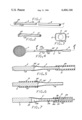
- FIG. 1 is a perspective view of the mandrel and a tube of heat softenable plastic that is used in forming the guide;
- FIG. 2 is a perspective view of the guide after the same has been formed and longitudinally slid from the mandrel;
- FIG. 3 is an end view of the guide after circumferentially spaced, longitudinally extending strips of an anti-friction tape have been mounted thereon;
- FIG. 4 is a plan view of a handle of a tennis or racquet ball handle that is removably engaged by the guide, and a sleeve of elastomeric material that is to define the grip in engagement with the guide;
- FIG. 5 is a longitudinal cross sectional view of the handle, guide and sleeve taken on the line 5--5 of FIG. 4;
- FIG. 6 is the same view as shown in FIG. 4 but after the sleeve is mounted on the handle, but prior to the guide being disengaged from the sleeve;
- FIG. 7 is a longitudinal cross sectional view of an alternate form of guide for mounting a tube of elastomeric material on an elongate rigid member.
- FIG. 1 an elongate rigid mandrel A is shown that is adapted to have a tube B of a heated polymerized resin such as PVC longitudinally slid thereover to transform the tube into the guide C shown in FIG. 2.
- a tennis or racquet ball racquet F that has a handle E may have a tube D of elastomeric material mounted thereon by use of the guide C to define a grip D'.
- the handle E of both tennis and racquet ball racquets F has a gripable portion 10 that is of substantially square transverse cross section, and is conventionally defined by four longitudinal flat surfaces 10a and flat angled corner edge surfaces 10b.
- the tube D of elastomeric material when not stressed circumferentially has an internal cross sectional area 12 that is less than the transverse cross sectional area 14 of the handle E, and as previously mentioned the exterior surface of the handle and the interior surface of tube D are of different shapes when the tube is not stressed circumferentially.
- the mandrel A is formed from a metal such as steel and includes a first longitudinal portion 16 that has a circular transverse cross sectional area 18 that is substantially less than the interior transverse cross sectional area 12 of elastomeric tube B.
- Mandrel A also includes a longitudinal end portion 20 of substantially the same shape but of slightly larger transverse cross sectional area than that of the gripable portion 10a of handle E.
- the longitudinal end portion 20 merges into the longitudinal portion 16 by a smooth transition portion 22 situated therebetween as shown in FIG. 1.
- the tube When mandrel A and tube B are heated to the extent that the resin defining the tube softens, the tube may be moved longitudinally on the mandrel and in so doing acquiring the shape of the mandrel to provide the guide C shown in FIG. 2.
- the guide C After the guide C has cooled to the extent that the resin defining the same is rigid, the guide is slid longitudinally from the mandrel.
- the guide C includes portions 16', 20' and 22' that correspond in shape to portions 16, 20 and 22 of mandrel A.
- the external diameter of the portion 16' of guide C is such that it may be inserted into the interior of elastomeric tube D.
- the portion 20' of guide C has such an interior transverse cross sectional area that the portion 20' may be slipped longitudinally onto the gripable portion 10' of handle E as shown in FIG. 5.
- the guide C has a number of strips G of tape attached in longitudinally extending positions thereon as shown in FIG. 4.
- Each strip G has a pressure sensitive adhesive on both sides thereof.
- a suitable liquid such as paint thinner, naptha or mineral spirits the adhesive becomes slippery.
- a suitable tape for this purpose is 3M, Model 410.
- Tube D is now slid longitudinally on guide C, with this movement being eased due to the interior surface 24 of the tube sliding on the slippery surfaces of the tapes G.
- longitudinal movement of the tube D takes place it is sequentially deformed to the external configuration of the gripable portion 10 of handle C as shown in FIG. 6.
- Longitudinal movement of the tube D over the gripable portion 10 of handle E is facilitated by a portion of the slippery adhesive rubbing off from the strips G onto the internal surface 24 serves as a lubricant in moving the tube D on handle E.
- the guide C is removed.
- Tube D is not only circumferentially deformed to define grip D', but is also circumferentially tensioned to remain in a frictional gripping position on the handle E.
- the PVC used in forming the guide C is preferably of the Class 200, which is a well known designation in the trade as in Permalite for the centerless ground rubber tube D.
- FIG. 7 An alternate form of the invention is shown in FIG. 7 in which a guide C' is provided that is the same as the guide C, with the exception that the strips G are omitted therefrom, and in their place a number of longitudinally spaced ports 28 are formed in the guide.
- the guide C' may be caused to snuggly engage an end portion 30 of an elongate object L that may be a handle of a racquet, end portion of a flash light, bicycle grip, or the like.
- a rigid conduit 32 is provided that is connected to a source of pressurized air (not shown).
- the conduit 32 on a free end 34 thereof supports a nozzle 36 that has a tapered external surface 36a that removably and sealingly engages the guide C'.
- air under pressure is directed into the guide C' through nozzle 36 it flows outwardly through the ports 28, and radially expands the interior surface 24 of elastomeric tube D to the extent it may be slid longitudinally over the guide C' onto the elongate member L to envelop the latter.
- Tube D after mounting an elongate member L by use of the alternate form of the invention shown in FIG. 7, transforms to a grip D' or protective cover as illustrated in FIG. 6.
Landscapes
- Engineering & Computer Science (AREA)
- Mechanical Engineering (AREA)
- Health & Medical Sciences (AREA)
- General Health & Medical Sciences (AREA)
- Physical Education & Sports Medicine (AREA)
- Golf Clubs (AREA)
Abstract
Description
Claims (2)
Priority Applications (1)
| Application Number | Priority Date | Filing Date | Title |
|---|---|---|---|
| US06/266,202 US4466166A (en) | 1981-05-22 | 1981-05-22 | Grip mounting assembly |
Applications Claiming Priority (1)
| Application Number | Priority Date | Filing Date | Title |
|---|---|---|---|
| US06/266,202 US4466166A (en) | 1981-05-22 | 1981-05-22 | Grip mounting assembly |
Publications (1)
| Publication Number | Publication Date |
|---|---|
| US4466166A true US4466166A (en) | 1984-08-21 |
Family
ID=23013601
Family Applications (1)
| Application Number | Title | Priority Date | Filing Date |
|---|---|---|---|
| US06/266,202 Expired - Fee Related US4466166A (en) | 1981-05-22 | 1981-05-22 | Grip mounting assembly |
Country Status (1)
| Country | Link |
|---|---|
| US (1) | US4466166A (en) |
Cited By (19)
| Publication number | Priority date | Publication date | Assignee | Title |
|---|---|---|---|---|
| US4653170A (en) * | 1986-01-10 | 1987-03-31 | Kelson Arnold A | Method for handlebar grip installation |
| US4729256A (en) * | 1986-01-10 | 1988-03-08 | Kelson Arnold A | Handlebar grip and assembling facilitating strip |
| US4736506A (en) * | 1986-10-09 | 1988-04-12 | Tacki-Mac Grips, Inc. | Bat grip installation device |
| US4843668A (en) * | 1988-02-18 | 1989-07-04 | Jerry Bondar | Hand tool for storing and applying O-ring seals |
| US4912836A (en) * | 1987-01-30 | 1990-04-03 | Avetoom Garnic C | Method of installing a sports equipment grip |
| US5074023A (en) * | 1987-10-07 | 1991-12-24 | Bettcher Industries, Inc. | Method and apparatus for applying a handle cover |
| US5373616A (en) * | 1993-03-31 | 1994-12-20 | Boa, Inc. | Apparatus for applying hangrips to articles such as sports equipment and the like |
| US5407026A (en) * | 1993-12-07 | 1995-04-18 | Karsten Manufacturing Corporation | Golf club grip installing apparatus |
| US5419031A (en) * | 1993-09-17 | 1995-05-30 | Mclendon; Rob E. | Attachable golf club grip for the layman |
| US5477603A (en) * | 1994-05-09 | 1995-12-26 | Chrysler Corporation | Apparatus and method to guide a control assembly through an instrument panel opening |
| GB2323296A (en) * | 1997-03-18 | 1998-09-23 | Jan Adriaan Vorster | Applying rubber grips to sports articles |
| US6317949B1 (en) * | 1999-11-22 | 2001-11-20 | Allen Ray Dotson | Device for banding together components of a fishing lure |
| US6401321B2 (en) * | 1996-05-02 | 2002-06-11 | Burgoo Holdings Limited | Application of grips to handles |
| US6665978B1 (en) | 2002-07-31 | 2003-12-23 | Ross J. Reed | Fishing hook bait attachment device and method |
| US20090282669A1 (en) * | 2008-05-13 | 2009-11-19 | Randolf Von Oepen | Method And Apparatus For Reducing Stress During Stent Manufacture |
| US20090313802A1 (en) * | 2005-06-10 | 2009-12-24 | Mark Schell | Method and apparatus for fitting grips |
| US20110074128A1 (en) * | 2009-09-25 | 2011-03-31 | Jonathan Chang | Elastomeric grip tape |
| US9003592B2 (en) | 2012-05-24 | 2015-04-14 | Kaj Zingo Smith | Cleaning pole sleeve |
| US20160175669A1 (en) * | 2013-07-31 | 2016-06-23 | Jai Choon SIN | Grip aid for golf club |
Citations (8)
| Publication number | Priority date | Publication date | Assignee | Title |
|---|---|---|---|---|
| US2877070A (en) * | 1956-03-30 | 1959-03-10 | Luther E Lee | Fluid pressure seal |
| FR1239168A (en) * | 1959-10-28 | 1960-12-07 | Hand tool for fitting the cap of hydraulic brake cups | |
| US3073016A (en) * | 1959-06-18 | 1963-01-15 | Clevite Harris Products Inc | Punch for assembling rubber bushings |
| US3369286A (en) * | 1962-11-15 | 1968-02-20 | Clevite Corp | Tool for assembling bushings |
| US3833992A (en) * | 1973-06-01 | 1974-09-10 | Hughes Aircraft Co | Assembly tool for replacement of wire seal, electrical contact |
| US3900941A (en) * | 1974-02-08 | 1975-08-26 | Dayco Corp | Apparatus for and method of installing an expandible sleeve |
| US4185375A (en) * | 1976-04-09 | 1980-01-29 | Brown Horace R | Method of applying handle coverings |
| US4291451A (en) * | 1979-08-13 | 1981-09-29 | Neill Brian S O | O-Ring tool |
-
1981
- 1981-05-22 US US06/266,202 patent/US4466166A/en not_active Expired - Fee Related
Patent Citations (8)
| Publication number | Priority date | Publication date | Assignee | Title |
|---|---|---|---|---|
| US2877070A (en) * | 1956-03-30 | 1959-03-10 | Luther E Lee | Fluid pressure seal |
| US3073016A (en) * | 1959-06-18 | 1963-01-15 | Clevite Harris Products Inc | Punch for assembling rubber bushings |
| FR1239168A (en) * | 1959-10-28 | 1960-12-07 | Hand tool for fitting the cap of hydraulic brake cups | |
| US3369286A (en) * | 1962-11-15 | 1968-02-20 | Clevite Corp | Tool for assembling bushings |
| US3833992A (en) * | 1973-06-01 | 1974-09-10 | Hughes Aircraft Co | Assembly tool for replacement of wire seal, electrical contact |
| US3900941A (en) * | 1974-02-08 | 1975-08-26 | Dayco Corp | Apparatus for and method of installing an expandible sleeve |
| US4185375A (en) * | 1976-04-09 | 1980-01-29 | Brown Horace R | Method of applying handle coverings |
| US4291451A (en) * | 1979-08-13 | 1981-09-29 | Neill Brian S O | O-Ring tool |
Cited By (22)
| Publication number | Priority date | Publication date | Assignee | Title |
|---|---|---|---|---|
| US4729256A (en) * | 1986-01-10 | 1988-03-08 | Kelson Arnold A | Handlebar grip and assembling facilitating strip |
| US4653170A (en) * | 1986-01-10 | 1987-03-31 | Kelson Arnold A | Method for handlebar grip installation |
| US4736506A (en) * | 1986-10-09 | 1988-04-12 | Tacki-Mac Grips, Inc. | Bat grip installation device |
| US4912836A (en) * | 1987-01-30 | 1990-04-03 | Avetoom Garnic C | Method of installing a sports equipment grip |
| US5074023A (en) * | 1987-10-07 | 1991-12-24 | Bettcher Industries, Inc. | Method and apparatus for applying a handle cover |
| US4843668A (en) * | 1988-02-18 | 1989-07-04 | Jerry Bondar | Hand tool for storing and applying O-ring seals |
| US5373616A (en) * | 1993-03-31 | 1994-12-20 | Boa, Inc. | Apparatus for applying hangrips to articles such as sports equipment and the like |
| US5419031A (en) * | 1993-09-17 | 1995-05-30 | Mclendon; Rob E. | Attachable golf club grip for the layman |
| US5407026A (en) * | 1993-12-07 | 1995-04-18 | Karsten Manufacturing Corporation | Golf club grip installing apparatus |
| US5477603A (en) * | 1994-05-09 | 1995-12-26 | Chrysler Corporation | Apparatus and method to guide a control assembly through an instrument panel opening |
| US6401321B2 (en) * | 1996-05-02 | 2002-06-11 | Burgoo Holdings Limited | Application of grips to handles |
| GB2323296A (en) * | 1997-03-18 | 1998-09-23 | Jan Adriaan Vorster | Applying rubber grips to sports articles |
| US6317949B1 (en) * | 1999-11-22 | 2001-11-20 | Allen Ray Dotson | Device for banding together components of a fishing lure |
| US6665978B1 (en) | 2002-07-31 | 2003-12-23 | Ross J. Reed | Fishing hook bait attachment device and method |
| US20090313802A1 (en) * | 2005-06-10 | 2009-12-24 | Mark Schell | Method and apparatus for fitting grips |
| US20090282669A1 (en) * | 2008-05-13 | 2009-11-19 | Randolf Von Oepen | Method And Apparatus For Reducing Stress During Stent Manufacture |
| US8261420B2 (en) * | 2008-05-13 | 2012-09-11 | Abbott Laboratories | Method and apparatus for reducing stress during stent manufacture |
| US20110074128A1 (en) * | 2009-09-25 | 2011-03-31 | Jonathan Chang | Elastomeric grip tape |
| WO2011038276A3 (en) * | 2009-09-25 | 2011-10-06 | Jonathan Chang | Elastomeric grip tape |
| US9003592B2 (en) | 2012-05-24 | 2015-04-14 | Kaj Zingo Smith | Cleaning pole sleeve |
| US20160175669A1 (en) * | 2013-07-31 | 2016-06-23 | Jai Choon SIN | Grip aid for golf club |
| US9662552B2 (en) * | 2013-07-31 | 2017-05-30 | Jai Choon SIN | Grip aid for golf club |
Similar Documents
| Publication | Publication Date | Title |
|---|---|---|
| US4466166A (en) | Grip mounting assembly | |
| US6223628B1 (en) | Light bulb remover | |
| US5992697A (en) | Water squirting device | |
| US4912836A (en) | Method of installing a sports equipment grip | |
| US4185375A (en) | Method of applying handle coverings | |
| US5188409A (en) | Golf ball retriever | |
| FR2401729A1 (en) | MOTORIZED SCREWDRIVER CHUCK | |
| US5611533A (en) | Gripping sleeve apparatus and method of using the same | |
| CA2325961C (en) | Golf club grip assembly | |
| US4862970A (en) | Greens repair tool | |
| AU718324B2 (en) | Application of grips to handles | |
| IE45761L (en) | Venipuncture device | |
| US8915529B1 (en) | Device for aiding a user in removing items from a truck bed | |
| US3005441A (en) | Thumb mounted pencil holder | |
| US5445424A (en) | Automatic arrow extractor | |
| US11400353B1 (en) | Setting tool for golf ball and golf tee | |
| US3935758A (en) | Tool for applying masking tape to moldings | |
| GB2120102A (en) | Method and device for applying an elastic sheath to a penis | |
| US1557156A (en) | Extension handle for golf sticks | |
| US2840896A (en) | Method for applying grips to hockey sticks and the like | |
| US6048274A (en) | Apparatus for performing golf-related tasks | |
| US5172910A (en) | Method and apparatus for improving bowling ball control | |
| US5393581A (en) | Readily applied and removed shield for graphite shafts | |
| JPH10511898A (en) | Method for cutting metal reinforced hoses, metal pipes and the like, and apparatus for utilizing this method | |
| CA2493824A1 (en) | Moisture-absorbing collar for a safety razor |
Legal Events
| Date | Code | Title | Description |
|---|---|---|---|
| FEPP | Fee payment procedure |
Free format text: PAYOR NUMBER ASSIGNED (ORIGINAL EVENT CODE: ASPN); ENTITY STATUS OF PATENT OWNER: SMALL ENTITY |
|
| FPAY | Fee payment |
Year of fee payment: 4 |
|
| AS | Assignment |
Owner name: GRIP-TECH INTERNAITONAL, INC., 32 SWEET MEADOW COU Free format text: ASSIGNMENT OF ASSIGNORS INTEREST.;ASSIGNOR:HOGARTH, HAROLD, W.;REEL/FRAME:004917/0183 Effective date: 19880804 |
|
| FEPP | Fee payment procedure |
Free format text: PAYOR NUMBER ASSIGNED (ORIGINAL EVENT CODE: ASPN); ENTITY STATUS OF PATENT OWNER: SMALL ENTITY Free format text: PAYER NUMBER DE-ASSIGNED (ORIGINAL EVENT CODE: RMPN); ENTITY STATUS OF PATENT OWNER: SMALL ENTITY |
|
| FPAY | Fee payment |
Year of fee payment: 8 |
|
| REMI | Maintenance fee reminder mailed | ||
| LAPS | Lapse for failure to pay maintenance fees | ||
| FP | Lapsed due to failure to pay maintenance fee |
Effective date: 19960821 |
|
| STCH | Information on status: patent discontinuation |
Free format text: PATENT EXPIRED DUE TO NONPAYMENT OF MAINTENANCE FEES UNDER 37 CFR 1.362 |