US4465226A - Paperboard tray corner construction - Google Patents
Paperboard tray corner construction Download PDFInfo
- Publication number
- US4465226A US4465226A US06/352,801 US35280182A US4465226A US 4465226 A US4465226 A US 4465226A US 35280182 A US35280182 A US 35280182A US 4465226 A US4465226 A US 4465226A
- Authority
- US
- United States
- Prior art keywords
- tray
- blank
- weakening
- width
- flaps
- Prior art date
- Legal status (The legal status is an assumption and is not a legal conclusion. Google has not performed a legal analysis and makes no representation as to the accuracy of the status listed.)
- Expired - Fee Related
Links
- 239000011087 paperboard Substances 0.000 title abstract description 10
- 238000010276 construction Methods 0.000 title description 2
- 239000003292 glue Substances 0.000 claims abstract description 13
- 230000003313 weakening effect Effects 0.000 claims description 22
- 238000004806 packaging method and process Methods 0.000 claims description 2
- 230000006835 compression Effects 0.000 abstract description 11
- 238000007906 compression Methods 0.000 abstract description 11
- 238000004026 adhesive bonding Methods 0.000 abstract description 2
- 229920006300 shrink film Polymers 0.000 description 4
- 239000000463 material Substances 0.000 description 3
- 239000013536 elastomeric material Substances 0.000 description 2
- 230000015572 biosynthetic process Effects 0.000 description 1
- 238000000034 method Methods 0.000 description 1
- 239000004033 plastic Substances 0.000 description 1
- -1 polytetrafluoroethylene Polymers 0.000 description 1
- 229920001343 polytetrafluoroethylene Polymers 0.000 description 1
- 239000004810 polytetrafluoroethylene Substances 0.000 description 1
Images


Classifications
-
- B—PERFORMING OPERATIONS; TRANSPORTING
- B65—CONVEYING; PACKING; STORING; HANDLING THIN OR FILAMENTARY MATERIAL
- B65D—CONTAINERS FOR STORAGE OR TRANSPORT OF ARTICLES OR MATERIALS, e.g. BAGS, BARRELS, BOTTLES, BOXES, CANS, CARTONS, CRATES, DRUMS, JARS, TANKS, HOPPERS, FORWARDING CONTAINERS; ACCESSORIES, CLOSURES, OR FITTINGS THEREFOR; PACKAGING ELEMENTS; PACKAGES
- B65D5/00—Rigid or semi-rigid containers of polygonal cross-section, e.g. boxes, cartons or trays, formed by folding or erecting one or more blanks made of paper
- B65D5/20—Rigid or semi-rigid containers of polygonal cross-section, e.g. boxes, cartons or trays, formed by folding or erecting one or more blanks made of paper by folding-up portions connected to a central panel from all sides to form a container body, e.g. of tray-like form
- B65D5/28—Rigid or semi-rigid containers of polygonal cross-section, e.g. boxes, cartons or trays, formed by folding or erecting one or more blanks made of paper by folding-up portions connected to a central panel from all sides to form a container body, e.g. of tray-like form with extensions of sides permanently secured to adjacent sides, with sides permanently secured together by adhesive strips, or with sides held in place solely by rigidity of material
Definitions
- This invention relates generally to paperboard tray blanks of the type having side and end flaps adapted to being folded upwardly so as to receive a charge or slug of articles, usually cylindrical cans.
- the cost of the paperboard material has become high enough to warrant minimizing the height of these tray flaps so as to minimize the quantity of paperboard material required in the making up of a typical package.
- Shrink film wrapping is generally provided around the product in the paperboard tray but the application of the shrink film forms no part of the present invention.
- the height of the side and end walls is dictated by the depth of a laterally open slot provided adjacent each of the corners of the tray blank, and lines of weakening or score lines are generally provided at some predetermined distance for the marginal edges of the blank, corresponding to the depth of these slots.
- the leading and trailing end flaps are generally bent upwardly in a preliminary step during the formation of the tray, and the side and end flaps are then folded upwardly to form a tray and to permit the application of pressure to set the glue between these corner tabs and the forward and leading end portions of these side flaps.
- the tray blank is adapted to hold product, in the form of cans or other cylindrical articles, having a diameter D which is related to the height of the side and end flaps in the ratio of three to one or less.
- L-shaped slots are formed adjacent the corners of the tray blank with each slot having one leg aligned with the line of weakening between the bottom panel of the tray blank and one of said end flaps, and having its outer leg generally aligned with the line of weakening between said bottom panel and the side flap.
- This latter leg has a maximum width such that one side of the slot leg is aligned with the line of weakening and the other side is aligned with a short line of weakening forming a corner tab such that the corner tab has a depth h plus ⁇ where ⁇ corresponds to the maximum width of this leg of the L shaped slot.
- the above mentioned tray configuration permits the folding up of a paperboard tray such that the end portions of the corner tab are located adjacent to the periphery of the cylindrical can in the tray with the result that compression exerted against the side walls or flaps of the tray can set the glue between the ends of these side flaps and the corner tab itself.
- the present invention also encompasses a unique compression unit especially suited for applying side pressure to a folded and glued tray blank, which tray may have irregularly shaped end portions in that these end portions are slightly tapered rather than being square as is the case in a conventional rectangular tray.
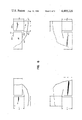
- FIG. 1 is a plan view of one corner of a generally rectangular four cornered tray blank of the type found in the prior art.
- FIG. 2 is a plan view of the prior art tray blank depicted in FIG. 1, but folded up and glued in a conventional fashion (except for the fact that the height of the tray H is equal to or less than one-third the diameter of the product P, an uncoventional limitation).
- FIG. 3 is a plan view similar to FIG. 1 but illustrating one corner of an improved tray blank having a generally rectangular configuration with four corners of the type depicted in FIG. 3.
- FIG. 4 is a plan view of the tray blank illustrated in FIG. 3 but with the side and end flaps folded upwardly, and with the corner tab glued in place so as to hold a plurality of cylindrical articles within the tray.
- FIG. 5 is a plan view of an improved tray compression section or unit, such as might be utilized for setting the glue in the tray of FIG. 4.
- FIG. 6 is a fragmentary plan view showing the four corners of a tray blank.
- FIGS. 1 and 2 show a conventional paperboard tray blank 10 of the type adapted to hold a plurality of articles such as cans or the like in order that further packaging can be accomplished, as for example of surrounding the package suggested in FIGS. 1 and 2 with a shrink film wrapping.
- FIG. 1 shows a tray blank prior to its being folded into the configuration for wrapping the product and tray with such a shrink film.
- the tray blank includes a bottom panel 14 defined by mutually perpendicular lines of weakening 10e and 10g, oppositely paired with respect to one another so as to define a generally rectangular bottom panel 14.
- Side flaps 10b are integrally connected to the sides of the bottom panel 14 along lines of weakening such as that shown at 10e.
- End flaps 10f are similarly connected integrally to the ends of the bottom panel 14 along lines of weakening such as that illustrated at 10g.
- the dimension "h” in FIG. 1 illustrates the ultimate height for the tray (less some minimal difference due to the thickness of the paperboard blank "t” and this dimension "h” is defined for purposes of this application as being the spacing between the outer marginal edges of the side and end flaps and the lines of weakening 10e and 10g.
- FIG. 2 illustrates the relative size of the cans or product P to be packaged in a tray of the type shown in FIG. 1 and for purposes of comparison FIG. 2 shows this diameter D for the product P as being approximately three times the dimension "h" referred to previously.
- FIGS. 3 and 4 illustrate an improved tray blank 20 constructed of the same material as that referred to in the foregoing description of FIGS. 1 and 2.
- the tray blank 20 has a thickness "t" as suggested in FIG. 4 and is intended to be used with cans or product of a diameter equal to or less than three times the dimension "h" of the side and end flaps.
- the blank of FIG. 3 includes generally L-shaped slots 20c formed adjacent to the corners of the tray blank 20. Each L-shaped slot has one leg aligned with a line of weakening 20g between the bottom panel 24 and the end flap 20f.
- This leg of the slot 20c is somewhat deeper than the slot 10c illustrated in the prior art tray blank of FIG. 1. This increase in depth is illustrated by the dimension h plus ⁇ in FIG. 3. It should be noted that the distance between the side and end flaps with respect to the lines of weakening 20e and 20g in FIG. 3 still comprises the dimension "h" referred to previously with reference to FIGS. 1 and 2. That is, the dimension "h” is such that the ratio D/h ⁇ 3.
- each of these slots has its other leg perpendicular to the first mentioned leg and aligned generally with the line of weakening 20e associated with the bottom panel 24 and the side flap 20b.
- this last mentioned leg of the L-shaped slot 20c has a tapered width such that one side of said slot (the outer side) is in fact aligned with the line of weakening 20e, and the other side of said slot is so tapered that its widest point is generally aligned with a short line of weakening segment 20 d extending across the end flap 20f and spaced from the outer marginal edge of side flap 20b by the above mentioned dimension h plus ⁇ .
- This line of weakening 20d defines a corner tab 20a, which corner tab has a lateral dimension h plus ⁇ greater than the lateral dimension "h" of the corner tab 10a referred to in the otherwise conventional prior art tray blank of FIG. 1.
- FIG. 5 shows the folded up tray blank of FIG. 4 in the process of being moved in the direction of the arrow 26 between opposed compressible elements 28 (one shown).
- an inward force is exerted against the slot defining side flaps 20b and the corner tab 20a to compress the glue between said slide flap 20b and the tab 20a.
- Conventional means is provided for advancing the tray 20 and its product P through this compression unit or section, and the resilient compressive elastomeric elements 28 may each comprise an elastomeric material 28 backed up by rigid side walls 30.
- a low friction plastic skin 32 of polytetrafluoroethylene or the like is provided on the outer face of each compressive elastomeric element 28.
- These elements 28 are preferably formed from an elastomeric material having sufficient resiliency to allow the trays to be advanced therebetween. In their uncompressed condition these elements 28 define a path for the trays, which path has a lateral width at least two times the dimension ⁇ less than the overall tray width in the lateral direction.
Landscapes
- Engineering & Computer Science (AREA)
- Mechanical Engineering (AREA)
- Packages (AREA)
Abstract
Description
Claims (6)
Priority Applications (1)
| Application Number | Priority Date | Filing Date | Title |
|---|---|---|---|
| US06/352,801 US4465226A (en) | 1982-02-26 | 1982-02-26 | Paperboard tray corner construction |
Applications Claiming Priority (1)
| Application Number | Priority Date | Filing Date | Title |
|---|---|---|---|
| US06/352,801 US4465226A (en) | 1982-02-26 | 1982-02-26 | Paperboard tray corner construction |
Publications (1)
| Publication Number | Publication Date |
|---|---|
| US4465226A true US4465226A (en) | 1984-08-14 |
Family
ID=23386544
Family Applications (1)
| Application Number | Title | Priority Date | Filing Date |
|---|---|---|---|
| US06/352,801 Expired - Fee Related US4465226A (en) | 1982-02-26 | 1982-02-26 | Paperboard tray corner construction |
Country Status (1)
| Country | Link |
|---|---|
| US (1) | US4465226A (en) |
Cited By (4)
| Publication number | Priority date | Publication date | Assignee | Title |
|---|---|---|---|---|
| US5195644A (en) * | 1992-07-13 | 1993-03-23 | Glenayre Electronics Ltd. | Sealed, seamless box and method of manufacturing same |
| FR2821335A1 (en) * | 2001-02-23 | 2002-08-30 | Otor Sa | TRAY, BLANK AND PACKAGING FOR BOXES OR CYLINDRICAL PRODUCTS |
| WO2006130107A1 (en) * | 2005-05-31 | 2006-12-07 | Smurfit Packaging Ab | Tray and method for erecting a tray |
| US20080066953A1 (en) * | 2006-09-19 | 2008-03-20 | Fujitsu Limited | Circuit board assembly and manufacturing method thereof, electronic part assembly and manufacturing method thereof, and electronic device |
Citations (9)
| Publication number | Priority date | Publication date | Assignee | Title |
|---|---|---|---|---|
| US1493181A (en) * | 1923-02-17 | 1924-05-06 | Zwick Harry | Construction of file-cabinet drawers |
| US2265326A (en) * | 1939-03-02 | 1941-12-09 | Diamond Paper And Box Co | Collapsible box |
| US2424716A (en) * | 1945-06-20 | 1947-07-29 | Ralph F Smart | Foldable cardboard box |
| US2858058A (en) * | 1954-12-10 | 1958-10-28 | Union Bag Camp Paper Corp | Produce box |
| US3416288A (en) * | 1965-10-18 | 1968-12-17 | Olinkraft Inc | Method of shrink-packaging utilizing a self-erecting pallet |
| US3474901A (en) * | 1967-10-16 | 1969-10-28 | Inland Steel Co | Octagonal pallets,blanks and methods for forming same and a container package utilizing the pallet |
| US3837562A (en) * | 1972-07-03 | 1974-09-24 | A Cali | Container for packaging papers |
| US3841476A (en) * | 1971-11-15 | 1974-10-15 | P Elford | Cartons, trays and the like |
| US4114798A (en) * | 1977-10-28 | 1978-09-19 | Container Corporation Of America | Interlocking cover and tray |
-
1982
- 1982-02-26 US US06/352,801 patent/US4465226A/en not_active Expired - Fee Related
Patent Citations (9)
| Publication number | Priority date | Publication date | Assignee | Title |
|---|---|---|---|---|
| US1493181A (en) * | 1923-02-17 | 1924-05-06 | Zwick Harry | Construction of file-cabinet drawers |
| US2265326A (en) * | 1939-03-02 | 1941-12-09 | Diamond Paper And Box Co | Collapsible box |
| US2424716A (en) * | 1945-06-20 | 1947-07-29 | Ralph F Smart | Foldable cardboard box |
| US2858058A (en) * | 1954-12-10 | 1958-10-28 | Union Bag Camp Paper Corp | Produce box |
| US3416288A (en) * | 1965-10-18 | 1968-12-17 | Olinkraft Inc | Method of shrink-packaging utilizing a self-erecting pallet |
| US3474901A (en) * | 1967-10-16 | 1969-10-28 | Inland Steel Co | Octagonal pallets,blanks and methods for forming same and a container package utilizing the pallet |
| US3841476A (en) * | 1971-11-15 | 1974-10-15 | P Elford | Cartons, trays and the like |
| US3837562A (en) * | 1972-07-03 | 1974-09-24 | A Cali | Container for packaging papers |
| US4114798A (en) * | 1977-10-28 | 1978-09-19 | Container Corporation Of America | Interlocking cover and tray |
Cited By (4)
| Publication number | Priority date | Publication date | Assignee | Title |
|---|---|---|---|---|
| US5195644A (en) * | 1992-07-13 | 1993-03-23 | Glenayre Electronics Ltd. | Sealed, seamless box and method of manufacturing same |
| FR2821335A1 (en) * | 2001-02-23 | 2002-08-30 | Otor Sa | TRAY, BLANK AND PACKAGING FOR BOXES OR CYLINDRICAL PRODUCTS |
| WO2006130107A1 (en) * | 2005-05-31 | 2006-12-07 | Smurfit Packaging Ab | Tray and method for erecting a tray |
| US20080066953A1 (en) * | 2006-09-19 | 2008-03-20 | Fujitsu Limited | Circuit board assembly and manufacturing method thereof, electronic part assembly and manufacturing method thereof, and electronic device |
Similar Documents
| Publication | Publication Date | Title |
|---|---|---|
| US5375715A (en) | Polygonal section packaging of sheet material, in particular for bottles and a blank | |
| US4265390A (en) | Paperboard tray | |
| US3101167A (en) | Automatic bottom hexagonal carton | |
| US4007869A (en) | Corrugated carton constructions | |
| US3935943A (en) | Sealed carton formed from a pair of cooperating members | |
| US2870949A (en) | Cartons | |
| US5056707A (en) | Packaging | |
| US5529180A (en) | Semirigid packet for elongated elements, particularly cigarettes | |
| US2337198A (en) | Carton | |
| US3055574A (en) | Book mailing folder | |
| EP0761550A1 (en) | Box with retention and protection element for a jar | |
| US4465226A (en) | Paperboard tray corner construction | |
| US4171742A (en) | Corrugated fibreboard box | |
| US4784270A (en) | Corner post for shipping container | |
| US5520602A (en) | Method and adhesive pattern for a reverse fold sift proof carton | |
| US2778559A (en) | Blank for packaging of books and the like | |
| US3510047A (en) | Cardboard carton | |
| US6533164B1 (en) | Multi-featured blank for a food carton | |
| US2997220A (en) | Collapsible double walled cartons | |
| US3041942A (en) | Method of assembling multi-wall bulk pak shipping containers | |
| US4238031A (en) | Edge protector | |
| US3455496A (en) | Seal end carton | |
| US4160502A (en) | Platform carton | |
| US4159076A (en) | Sealed end carton | |
| US4017018A (en) | Carton closure |
Legal Events
| Date | Code | Title | Description |
|---|---|---|---|
| AS | Assignment |
Owner name: STANDARD-KNAPP, INC. PORTLAND, CT A CORP. OF CT Free format text: ASSIGNMENT OF ASSIGNORS INTEREST.;ASSIGNOR:FLANAGAN, THOMAS L.;REEL/FRAME:003978/0400 Effective date: 19820222 |
|
| AS | Assignment |
Owner name: UNITED BANK & TRUST COMPANY, A CT BANKING CORP OF Free format text: MORTGAGE;ASSIGNOR:NEW STANDARD-KNAPP, INC. A CORP OF CT;REEL/FRAME:004354/0422 Effective date: 19841222 Owner name: NEW STANDARD-KNAPP, INC., A CORP OF CT Free format text: ASSIGNMENT OF ASSIGNORS INTEREST.;ASSIGNOR:STANDARD-KNAPP, INC., A CORP OF CT;REEL/FRAME:004354/0414 Effective date: 19841222 |
|
| FEPP | Fee payment procedure |
Free format text: PAYOR NUMBER ASSIGNED (ORIGINAL EVENT CODE: ASPN); ENTITY STATUS OF PATENT OWNER: SMALL ENTITY |
|
| FPAY | Fee payment |
Year of fee payment: 4 |
|
| REMI | Maintenance fee reminder mailed | ||
| LAPS | Lapse for failure to pay maintenance fees | ||
| FP | Lapsed due to failure to pay maintenance fee |
Effective date: 19920816 |
|
| STCH | Information on status: patent discontinuation |
Free format text: PATENT EXPIRED DUE TO NONPAYMENT OF MAINTENANCE FEES UNDER 37 CFR 1.362 |