US4454738A - Roller leveler and method of operating same - Google Patents
Roller leveler and method of operating same Download PDFInfo
- Publication number
- US4454738A US4454738A US06/278,981 US27898181A US4454738A US 4454738 A US4454738 A US 4454738A US 27898181 A US27898181 A US 27898181A US 4454738 A US4454738 A US 4454738A
- Authority
- US
- United States
- Prior art keywords
- rollers
- roller
- frame
- distortion
- rolls
- Prior art date
- Legal status (The legal status is an assumption and is not a legal conclusion. Google has not performed a legal analysis and makes no representation as to the accuracy of the status listed.)
- Expired - Lifetime
Links
Images


Classifications
-
- B—PERFORMING OPERATIONS; TRANSPORTING
- B21—MECHANICAL METAL-WORKING WITHOUT ESSENTIALLY REMOVING MATERIAL; PUNCHING METAL
- B21D—WORKING OR PROCESSING OF SHEET METAL OR METAL TUBES, RODS OR PROFILES WITHOUT ESSENTIALLY REMOVING MATERIAL; PUNCHING METAL
- B21D1/00—Straightening, restoring form or removing local distortions of sheet metal or specific articles made therefrom; Stretching sheet metal combined with rolling
- B21D1/02—Straightening, restoring form or removing local distortions of sheet metal or specific articles made therefrom; Stretching sheet metal combined with rolling by rollers
Definitions
- This invention relates to means for flattening coiled metal strip, sheets and plates.
- Machines which perform this function are variously referred to as flatteners, levelers, straighteners, or roller levelers. All of these machines perform essentially the same function and operate substantially upon the same general principles. For the purposes of this application, the invention will be referred to as a roller leveler.
- roller leveler is equally suitable for processing sheets and plates, for illustrative purposes, the function of a roller leveler will be herein described in relation to coiled strip.
- Metal is formed into strip by a process known as rolling, wherein the strip is passed between a pair of work rolls of a rolling mill to reduce its cross-sectional thickness. In the process, the strip is elongated and rolling continues until the strip is reduced to the cross-sectional thickness desired.
- This rolling process may start with heated billets or slabs of metal, wherein the metal is rolled at a very high temperature, or it may start with previously rolled strip wherein the strip is passed between work rolls in the cold state. In either event, when the strip exits from the mill it may be convolutely wrapped to form a so-called coil.
- curvature of the coil tends to stay with the strip when it is necessary to uncoil the strip for further processing.
- the primary problem with strip coming off of a coil is the curvature which remains with the strip and which varies throughout the entire length of the coil as a function of the radius of any particular portion of the strip while in the coil. Accordingly, the outer wrap of the coil will have less curvature than an inner wrap.
- To remove this variable curvature in the strip is one of the purposes of a roller leveler. It is necessary to remove this curvature so that the strip may be cut accurately and rendered suitable for other manufacturing operations, such as punching, drawing, forming and the like.
- roller leveler The theory of operation of a roller leveler is quite simple in principle. It is to take an unknown problem and convert it into a known problem for which there is a known solution.
- the strip is taken from the coil it is not known what the particular degree of set is in any particular portion of the coil. Accordingly, the strip is passed through a combination of rollers which flex the strip a predetermined amount first in a given direction and then a predetermined amount in the opposite direction. Reverse flexing the strip in this manner by lesser and lesser amounts will eventually remove all curvature from it, irrespective of the degree of curvature set in the strip prior to entering the roller leveler.
- Strip rolled with thicker center portions indicates that greater pressure has been applied to the edges of the strip than at the center, thereby causing the edges to elongate at a greater rate than the center of the strip. Because this excess metal on the edges must go somewhere, but is restrained by the center, the result usually is a product having what is referred to as edge waves. In other words, the center of the strip is relatively flat longitudinally but the edges of the strip are sinusoidal. Strip rolled with edge waves is usually not saleable.
- the rolls may be so reinforced, or may be so contoured, that they resist or otherwise offset the wedge effect of the strip.
- the resultant is strip that is rolled thinner in the center than at the edges.
- the center of the strip tends to become elongated, producing a condition sometimes referred to as "oil canning".
- oil canning By this is meant that the elongated center portion of the strip compensates for this elongation by bulging either up or down.
- the result is strip that can literally be snapped up and down like the bottom of an oil can because of the stresses set up by this localized elongation.
- a strip coming to a roller leveler from a rolling mill could conceivably have several basic defects.
- the strip could have a curvature set because it was formed into a coil, the strip could have edge waves because its center was rolled thicker than its edges, the strip could have oil canning because its center was rolled thinner than its edges, or the strip could have combinations of these defects.
- roller levelers in addition to taking curvature out of coiled strip, could also remove the edge waves and/or the oil canning condition of the strip by skillful manipulation of the work rollers.
- an improperly operated roller leveler could create edge waving and/or oil canning in the strip.
- a roller leveler In order to avoid reducing the strip to poorer condition than when it was received, and at the same time correct what defects had been rolled into the strip from the mill, it has heretofore been necessary for an operator to continuously monitor and to adjust the work rollers of a roller leveler during the entire pass of the coil through the roller leveler. Obtaining a high quality of strip flatness from a prior art roller leveler is an art which can only be learned by an operator after many years of experience. Thus, it has been known in the prior art to bend the work rollers of a roller leveler to correct edge wave, oil canning and curvature. This is done by manipulating the work rollers of roller levelers.
- a roller leveler comprises an upper work roller and two lower work rollers.
- roller leveler In a practical industrial roller leveler the number of rollers are a matter of choice depending on the particular type of work being performed, and roller levelers having as many as twenty-nine rollers are known. It is also known that the more aggravated the condition of the non-flatness of the strip, the more rollers are required to bring the strip back to a flat condition. Particularly is this so in correcting edge waving and oil canning.
- a prior art roller leveler may include opposed upper and lower banks of work rollers and their associated back-up rolls.
- the upper bank of work rollers extends from side to side of the frame of the roller leveler and are positioned in parallel one behind the other from front to rear of the frame.
- the lower bank of work rollers also extends from side to side and from front to rear of the roller leveler frame and are parallel to the upper work rollers.
- the lower work rollers are offset so that an upper work roller may be brought substantially into tangential or nesting contact with a pair of lower work rollers.
- the spacing between the upper work roller and a pair of lower work rollers permits passage of the strip over a lower work roller, under the adjacent upper work roller and then over the next lower work roller.
- This spacing is referred to in the trade alternatively as the gap or plunge of the rollers.
- each bank of work rollers can be shifted vertically up or down as a unit to increase or lessen the plunge between the upper and lower work rollers.
- the upper and lower banks of rollers can also be tilted as a unit to provide decreasing plunge between the upper and lower work rollers from front to back.
- the flex of the strip at the entrance to the roller leveler may be relatively severe but this flexing will become less and less pronounced as the strip progresses between the work rollers from entrance to exit of the roller leveler.
- each work roller may have as many as five or more small back-up rolls in tangential contact therewith.
- Corresponding back-up rolls from work roller to work roller may be in alignment from front to rear of the roller leveler and this alignment is referred to as a flight of back-up rolls.
- each flight of back-up rolls is usually mounted on a massive beam, also extending from front to rear of the roller leveler frame. It is known for the beams to be moveable up or down but not to be tiltable. Only the entire bank of either upper or lower rolls are tiltable.
- manipulating the back-up roll beams which can be done by mechanical screw jacks, hydraulic cylinders, wedges and many other mechanical devices, the relative position of flights of back-up rolls may be adjusted within limits with respect to the work rollers.
- An experienced operator observing strip edge waving, oil canning or both can, by manipulating the back-up roll beams up or down, bend the work rollers to remove the edge wave or the oil canning.
- roller levelers It is not unusual in roller levelers for the strip work product to exert a total separation force against the work rolls of approximately two million pounds. Thus, in the case of a roller leveler having five sets of back-up rolls per work roller, the separation force would be two hundred tons per flight of back-up rolls. To perform a good job of flattening the strip, the operator might be required to set the desired gap between rollers within 0.001 to 0.002 inches. However, the separating force of the strip between the rollers could cause, even under normal operation, a roller deflection of 0.030 to 0.120 inches. Furthermore, in addition to causing roller bending, the separating forces of the strip also cause the frame itself to bend and to stretch.
- the inadequacy of the prior art roller levelers resides, therefore, in the fact that with the sides of the frame stretching, the crown of the frame bending, the base of the frame bending, and the rollers bending, there is no point of reference on the frame from which to maintain a predetermined gap between the rollers.
- a prior art roller leveler it would be ineffective to place a sensor on the crown of the frame to detect work roll deflection since it is conceivable that at the same time that the work roll is deflecting 0.030 inches the crown of the roller leveler is also deflecting 0.030 inches, whereby the sensor would read no deflection whatsoever.
- the sensor were mounted on the side of the roller leveler frame, wedging apart of the rollers by the strip could not be accurately measured because of the stretch in the sides of the frame.
- the principle objective of the subject invention is to provide means to pre-set and to automatically hold work rollers to a predetermined gap, irrespective of the varying forces acting on the roller leveler and the distortions in the work rollers and frame caused by these forces.
- the applicant conceived, in its preferred practical embodiment, a generally rectangular, sensor mounting structure with the upper corners of the structure secured to the opposite side members of the roller leveler frame. Except for these two contact points, the sensor structure is not otherwise supported or in contact with the roller leveler frame.
- the sensor structure comprises an upper horizontal cross piece spaced above the upper back-up rolls, and a lower cross piece spaced below the lower back-up rolls. As many sensors are mounted on each of these cross pieces as there are flights of back-up rolls, and the sensors are positioned as close as possible to the back-up roll mounting beams.
- the sensors are adapted to sense movement of the back-up rolls, the back-up roll mounting beams, the crown of the roller leveler frame, or the work rollers, is relatively immaterial since these deflections will all be substantially the same when acted upon by a workpiece passing through the roller leveler.
- the controlled gap can be maintained in several different ways.
- a horizontal gap is maintained between the work rollers during the leveling operation.
- the work rollers are permitted to bend but the bending is matched between the upper and lower work rolls so that the gap between corresponding portions of upper and lower work rollers is always maintained a substantially predetermined constant.
- the upper and lower rollers may bend but their curvatures will be arcs of concentric circles whereby the gap between rollers will not change.
- the second embodiment achieves a slightly less perfect flattening of the strip but is acceptable for most commercial applications.
- the first embodiment is employed wherein the upper and lower work rollers are maintained exactly where they are preset in order to maintain horizontal predetermined gaps across the spans of the upper and lower rollers. Both embodiments produce a quality of flatness superior to any prior art roller levelers known to applicant.
- first and second embodiments of the invention contemplate having each backup roll mounting beam adjustable at both the front and back portions, wherein the beam can be shifted vertically or tilted either toward the front or the rear of the roller leveler.
- each mounting beam separately adjustable both vertically and tiltably many more adjustment combinations can be made during the leveling process than possible by prior art roller levelers.
- the back-up roll mounting beams are articulated. In a preferred embodiment they are articulated at their mid-sections so as to provide combinations of roll adjustments along flights of back-up rolls. It is also contemplated that the beams may be articulated in two or more places.
- the back-up roll beams may be dispensed with and there is provided, in lieu thereof, a separate back-up roll adjustment device, such as a hydraulic cylinder, for each back-up roll, or set of back-up rolls, in a flight of back-up rolls.
- a separate back-up roll adjustment device such as a hydraulic cylinder
- every contact point on every work roll will be separately adjustable.
- each of these adjustments can be calibrated and programmed to be maintained at any position desired.
- the combinations of adjustments of back-up rolls and work rollers to cope with deformation of work strip are virtually limitless.
- roller leveler having improvements over prior art devices including: means to establish and to automatically maintain a desired plunge between upper and lower work rollers; means for full automation of the roller leveler; means to provide a fixed point of reference for making work roller adjustments; sensor means for continuously monitoring the shapes of the work rollers; non-deformable sensor mounting means; control means responsive to sensor signals to automatically adjust work roller shapes; means for accurately and automatically making roller shape adjustments responsive to sensor signals; electronic control means responsive to sensor signals to actuate hydraulic means to make work roller shape adjustments; means to adjust flights of back-up rolls both vertically and arcuately; articulated back-up roll support beams; individually adjustable back-up rolls; means to maintain predetermined roller gap or to change roller gap by automatically adjusting the back-up rolls of one bank of work rolls only; means to automatically maintain predetermined roller gap or to change roller gap by automatically adjusting the back-up rolls of both banks of work rollers; means to automatically maintain predetermined gaps between matching upper and lower work rollers; means to automatically maintain predetermined horizontal gaps
- roller leveler which will: process plates, strips and coils of metal of such imperfect shape that they could not be processed on prior art roller levelers; process cheaper grades of plates, strips and coils; process plates, strips and coils at higher production rates; be operable at lower labor costs; process plates, strips and coils to provide a better quality of flatness; process plates, strips and coils to more consistently provide a better quality of flatness; process plates, strips and coils with less rejected material; require less operator attention; and which will enable methods of operation heretofore not possible.
- FIG. 1 is a side elevational view of a preferred embodiment of the invention
- FIG. 2 is a front elevational view of the preferred embodiment of the invention shown in FIG. 1;
- FIG. 3 is an enlarged fragmentary side elevational view, partially in section, of the preferred embodiment of the invention as shown in FIGS. 1 and 2, taken along the line 3--3 of FIG. 2;
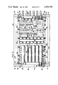
- FIG. 4 is an enlarged plan view, partially in section, of the preferred embodiment of the invention taken along the line 4--4 of FIG. 1;
- FIG. 5 is an enlarged fragmentary elevational view in section taken along the line 5--5 of FIG. 1;
- FIG. 6 is an enlarged fragmentary elevational view in section taken along the line 6--6 of FIG. 3;
- FIG. 7 is an elevational view of the non-deformable sensor mounting structure used in the preferred embodiments of the invention.
- FIG. 7A is a fragmentary elevational view of the sensor mounting structure taken along the line 7A--7A of FIG. 7;
- FIG. 8 is a schematic representation of a roller leveler having three rollers
- FIG. 9 is a schematic representation of the cross-section of a workpiece rolled thicker in the center than at the edges taken along the line 9--9 of FIG. 10;
- FIG. 10 is a schematic elevational representation of the edge waving of the workpiece taken along the line 10--10 of FIG. 9;
- FIG. 11 is a schematic representation of the cross-section of a workpiece rolled thinner in the center than at the edges taken along the line 11--11 of FIG. 12;
- FIG. 12 is a schematic elevational representation of the oil canning of the workpiece taken along the line 12--12 of FIG. 11;
- FIG. 13 is a schematic elevational view of the sensor mounting bracket secured to the side members of a roller leveler frame
- FIG. 14 is a schematic elevational side view of a roller leveler showing entrance and exit sensor mounting structures isolated from the forces of distortion to which the roller leveler frame is subject;
- FIG. 15 is a schematic elevational front view of a roller leveler showing the results of the forces of separation acting upon the rollers;
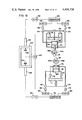
- FIG. 16 is a schematic representation of one preferred embodiment of roller leveler control means
- FIGS. 17 and 18 are schematic representations of one embodiment of gap maintenance between rollers that have been bent by the wedging action of the work product
- FIG. 19 is a schematic representation of a second preferred embodiment of roller leveler control means
- FIG. 20 is a schematic side elevational representation of an articulated back-up roll support beam used in a preferred embodiment of the invention.
- FIG. 21 is a schematic sectional view taken along the line 21--21 of FIG. 20;
- FIG. 22 is a schematic plan view taken along the line 22--22 of FIG. 21;
- FIG. 23 is a schematic elevational view, partially in section, showing a preferred embodiment of the invention wherein back-up rolls are individually adjustable;
- FIG. 24 is a schematic sectional view taken along the line 24--24 of FIG. 23;
- FIG. 25 is a schematic sectional view taken along the line 25--25 of FIG. 23.
- a roller leveler 10 comprising a weldment frame having steel side slabs 12, welded to base slab 11 to form the lower half of the frame 10.
- the upper half of frame 10 comprises slabs 14 welded to spacing members 16 which in turn are welded to slabs 18. Slabs 14 and 18 are thus spaced apart sufficiently to form clevises 17 which fit over the upper ends 19 of slabs 12 and are connected thereto by means of pins 20.
- journal beams 26 may be immoveably bolted to the upper portion of the frame such as with fastener means 28.
- journal beams 26 are mounted in gibs 34 so that they may be shifted vertically and/or arcuately, as will be described more fully hereinafter.
- a lower bank 30 of six separately driven rollers 38 is shown with opposite ends journaled in journal beams 32. Journal beams 32 are also fitted in gibs 35 to permit vertical and/or arcuate movement. It will be observed that rollers 25 of upper bank 24 are spaced to nest between pairs of lower rollers 38 in lower bank 30.
- a pinion stand 40 is provided whereby each of the upper rollers 25 and lower rollers 38 are individually driven by pinion stand drive shafts 42.
- a first pair of back-up rolls 46A-46B is in tangential contact with an adjacent work roller 38 forward of the vertical centerline 38A of the work roller and a second pair of back-up rolls 46A-46B is in tangential contact with this work roller rearward of the vertical centerline for a total flight of fourteen back-up rolls per mounting beam. Except for the outboard back-up rolls, forward and rearward of each flight, the intermediate back-up rolls are each in shared tangential supporting contact with a pair of work rollers 38.
- An hydraulic cylinder 48 is mounted under the front end of each back-up roll mounting beam 44, and a second hydraulic cylinder 50 is mounted under a rearward end of each back-up roll mounting beam. As more fully explained hereinafter, actuation of hydraulic cylinders 48 and 50 will cause back-up roll mounting beam 44 to shift vertically and/or arcuately to bring back-up rolls 46A and 46B into tangential pressure contact with adjacent work rollers 38.
- each mounting beam 52 carries a flight of back-up rolls 54A-54B arrayed front and rear of rollers 25 for tangential contact therewith.
- the flights of back-up rolls 54A-54B are aligned from front to rear of the roller leveler.
- a flight of six pairs of upper back-up rolls 54A-54B are mounted on each back-up roll mounting beam 52.
- the upper back-up rolls are also positioned so that each flight provides four back-up rolls in tangential contact with each upper work roller in the same manner as described with respect to lower back-up rolls 46A-46B. See also FIG. 6.
- An hydraulic cylinder 56 is mounted above the front end of each upper back-up roll mounting beam 52, and a second hydraulic cylinder 58 is mounted above the rearward end of each upper back-up roll mounting beam.
- actuation of hydraulic cylinders 56 and 58 will cause upper back-up roll beams 52 to shift vertically and/or arcuately to bring the upper back-up rolls 54A-54B into tangenetial pressure contact with adjacent work rollers 25.
- upper back-up roll mounting beams 52 may be immobilized by threaded fasteners 60 positioned at opposite ends and intermediate of each upper back-up roll mounting beam 52 to lock each beam into threaded engagement with upper slab member 62.
- Limited adjustment of the bank of upper back-up rolls 25 may be obtained by placing an appropriate number of spacers, washers or shims 61 between the beam 52 and upper slab member 62. It should be noted that whereas lower cylinders 48 and 50 rest on reinforced slab member 64, hydraulic cylinders 56 and 58 are suspended from the underside of reinforced slab member 66.
- Each lower back-up roll mounting beam 44 is stabilized against longitudinal shifting by a stabilizer rod 68, see FIGS. 3 and 4.
- One end of each rod is secured to frame trunnion 70 and the other end is secured to the back-up roll supporting beam 72.
- the stabilizing rod comprises an internally threaded center member 74 and external threaded members 76 which threadedly engage the opposite ends of the center member 74 to provide for the connections with trunnion 70 and beam portion 72.
- the upper back-up roll beams 52 are similarly stabilized against longitudinal shifting by stabilizing rods 68.
- the lower back-up roll beams 44 are supported on slab 77 only when the roller leveler is inoperative.
- FIG. 4 also illustrates the mounting of the ends of lower work rollers 38 in journal beams 32-32A.
- Keyways 78 are engaged by keys 80 to permit vertical and/or arcuate shifting of the journal beams 32-32A.
- Keys 80 are threadedly secured by fasteners 82 to slab portions 12 of the frame 10.
- Similar keys and keyways are provided with respect to the bank 24 of upper work rollers to permit vertical and/or arcuate shifting of this upper bank, including gib stop means 83, FIG. 1, to prevent the journal beams 26 from escaping downwardly from their gibs 34.
- Side thrust of work rollers is not considered a significant problem in the subject invention. Nevertheless, as shown in FIG.
- thrust bearings 86 are provided on the left ends of the upper and lower work rollers which adequately compensate for any unexpected lateral thrust which might develop during the operation of the leveler.
- plane bearings 88 are utilized to mount the roller ends in journal beam 32A.
- the clevis 17, comprised of slabs 14, 16, 18, is connected to lower slab 12 by means of pin 20.
- Clevis 17 is rigidly locked to lower slab 12 by means of set screws 90 and 91.
- Set screw 90 is brought into pressure contact with the upper surface 92 of slab 12 and held in place by lock nut 94.
- set screw 90 is threadedly received in cross member 96 against which lock nut 94 is brought into pressure contact.
- Set screw 91 FIG. 3, is threadedly mounted on saddle 93 which bridges upper slabs 14 and 18 so as to enable set screw 91 to be brought into pressure bearing contact with the upper end 19 of lower slab 12, and locked in place by lock nut 95.
- a non-deformable sensor mounting structure 100 which is comprised of light weight tubular cross-sectional members including lower cross piece 102, vertical support pieces 104, horizontal offset portions 106, vertical support pieces 108 and top horizontal cross piece 110.
- the lower cross piece member 102 is secured to the vertical support members 104 by threaded fasteners 112.
- Upper horizontal cross piece 110 is secured to vertical portions 108 by threaded fasteners 114.
- the entire sensor frame 100 is suspended within the roller leveler frame 10 by pins 116 which support the upper ends 118 of vertical members 108 within clevis members 120 and 122 secured to frame cross plate 124.
- the lower cross piece 102 has mounted thereon five evenly spaced apart sensors 126, each of which are further positioned to detect movement of a corresponding mounting beam, hydraulic cylinder, frame portion or the like, to directly or indirectly detect deflection or bending of a work roller.
- each sensor 126 may be positioned adjacent a corresponding back-up roll support beam 44 and adapted to detect movement of the beam.
- the upper cross piece 110 also carries five sensors 128 to detect movement of corresponding upper back-up roll support beams 52.
- the sensors in the embodiment shown in FIG. 7 are electromechanical transducers which transform mechanical movement into electrical signals.
- transducer per se, there being many commercially available transducers suitable for use in the invention.
- an electromechanical transducer was selected. Specifically, the Trans-Tek Incorporated Gaging Transducer DC-DC Series 350 was adopted. For the lower crosspiece sensors 126, Trans-Tek Model No. 354-000 was used. For the upper crosspiece sensors 128, Trans-Tek Model No. 352-000 was used.
- An example of a suitable commercially available sonic sensor is the Milltronics Microranger transducer.
- a suitable optic-fiber optic sensor is the Banner LED photoelectric scanner.
- a laser sensor suitable for use in the invention manufactured by M.E.A. Inc. is the NeHe measurement type laser operating on 5 milliwatts or less. Examples of fluid power positioning devices are described in the June 1981 issue of Control Engineering.
- roller leveler As briefly discussed heretofore, one of the primary functions of a roller leveler is to remove curvature from a piece of metal strip, sheet or plate.
- Strip is defined to mean metal which is sufficiently narrow and is rolled sufficiently thin that it can be wrapped into a coil.
- a sheet is defined as metal that is, for whatever reason, cut into lengths rather than stored in coiled form.
- Plate is metal which is too thick, as a practical matter, to be formed into a coil.
- the curvature would normally be of a substantially constant radius and the roller leveler means could be of the simplest form to flatten the sheet or plate.
- the roller leveler would theoretically require only a combination of three work rollers, such as schematically shown in FIG. 8 in exaggerated relationship for purposes of illustration.
- the roller leveler would comprise an upper work roller 130 and a pair of lower work rollers 132 and 134. It will be observed that a sheet S moving from right to left is flexed downwardly between upper work roller 130 and lower work roller 132 and then is reverse flexed between upper work roller 130 and lower work roller 134 which removes the simple curvature from the sheet.
- the upper work roller 130 and lower work rollers 132 and 134 must be properly positioned with respect to each other. This positioning will vary depending upon the amount of curvature which must be removed from the sheet.
- the upper and lower work rollers are vertically adjustable with respect to each other to increase or decrease the gap G between the rollers.
- the relationship between the upper and lower work rollers is sometimes referred to in terms of the "plunge".
- the plunge may be defined as the vertical measure between the lowermost point of the upper work roller and the uppermost point of the lower work rollers. Thus, if the vertical displacement between points P1 and P2 is one-quarter inch, it may be said that the plunge P of the work rollers is one-quarter inch.
- roller levelers The other important use of roller levelers is to make corrections in the shape of strip as it comes from the rolling mill. It has been previously noted that, when strip is passed between the rolls of a rolling mill, tremendous pressures are exerted against the rolls tending to force them apart. When this occurs the strip tends to be rolled thinner at the edges than in the center portion, as shown in FIG. 9, which is also exaggerated for purposes of illustration. It is understood that the difference between the thickness of the edges of the strip and of the center of the strip may be only a few thousandths of an inch or less. When this condition obtains, the edges of the strip are narrower because more metal has been rolled in these areas than in the center portion, resulting in edges which are longer than the center portion of the strip.
- edge waves W are defined as being the undulations caused when the edges of the strip are rolled thinner than the center portion.
- Strip may also be rolled with the center portion thinner than the edge portions, as shown in FIG. 11.
- the center of the strip is longer than the edges.
- the center of the strip undulates as shown at C and D in FIG. 12. This is the condition refered to as oil canning, wherein the positions of C and D shown in solid lines may reverse to the corresponding positions E and F shown in phantom.
- the strip at positions C and D may snap back and forth or reverse their relative positions to E and F because of this elongation in the center of the strip.
- a third condition of the strip is one in which the strip at various places along its longitudinal axis will vary between edge waving and oil canning.
- work rollers 25 and 38 are each supported by five flights of back-up rolls 54 and 46, respectively.
- Each flight of lower back-up rolls is supported by a back-up roll beam 44 and each flight of upper back-up rolls is supported by a back-up roll beam 52.
- Mounted to the front and rear of the roller leveler are non-deformable sensor mounting structures 100.
- Each lower back-up roll beam is provided with front and rear hydraulic adjustment cylinders 48 and 50 and each upper back-up roll beam is provided with front and rear hydraulic adjustment cylinders 56 and 58.
- each back-up roll mounting beam has both its forward and rearward portions monitored for movement by a corresponding sensor.
- sensor mounting structures 100 may be mounted on support means 136 isolated from the roller leveler frame, and are thereby totally free of the effects of frame distortion due to roller bending.
- upper and lower sensors will detect this bending movement away from the reference plane R located by sensor mounting structure 100.
- the difference between the actual position of the roller and reference plane R may be arbitrarily considered a positive deflection for purposes of illustration. This difference will be noted and a signal will be sent to the corresponding hydraulic cylinder 56 to urge the work roller 25 back to its intended position relative to the reference plane R.
- the hydraulic cylinder 56 would be signaled to retract to relieve the pressure on the back-up rollers 54A and 54B thereby permitting the work roller 25 to return to its preset position using plane R as a reference.
- the bottom work roller 38 is also preset relative to reference plane R and any deviation from the reference will provoke a similar signal to the corresponding hydraulic cylinder 48 to make the necessary correction.
- FIG. 16 therein is schematically shown a sensor mounting structure 100 upon which are mounted upper and lower sensors which sense upper and lower work roller deflections.
- a signal from upper sensor 128, detecting movement of an upper sensor detecting rod 134, and a constant signal from preset reference plane R indicator 140 are relayed to receiver 142 where the signals are amplified, conditioned, calibrated and the reference plane signal R is algebraically added to the work roller deflection signal X.
- the algebraic sum of these two signals provides a resultant signal which is forwarded to comparator 144.
- solenoid valve control 146 which directs the solenoid valve 148 to actuate hydraulic cylinder 56 to apply downward pressure to back-up rolls 54A and 54B until work roller 25 has been returned to the desired spacial relationship with reference to plane R.
- comparator 144 relays the signal to solenoid control 156.
- Solenoid control 156 directs solenoid valve 158 to actuate hydraulic cylinder 56 to remove appropriate downward pressure from back-up rolls 54A and 54B.
- hydraulic cylinder 56 is deactivated.
- a signal from lower sensor 126, detecting movement of a lower sensor detecting rod 134, and from preset reference plane R indicator 140 are relayed to receiver 150 where the signals are amplified, conditioned, calibrated and the reference plane signal R is algebraically added to the work roller deflection signal Y.
- the algebraic sum of these two signals provides a resultant signal which is forwarded to comparator 152.
- solenoid valve control 154 which directs the solenoid valve 162 to actuate hydraulic cylinder 48 to apply upward pressure to back-up rolls 46A and 46B until work roller 38 has been returned to the desired spacial relationship with reference plane R.
- solenoid control 160 directs solenoid valve 170 to actuate hydraulic cylinder 48 to remove appropriate upward pressure from back-up rolls 46A and 46B.
- hydraulic cylinder 48 is deactivated. The upward and downward movement of hydraulic cylinders 48 and 56 will be more or less continuous so long as upper and lower work rollers 25 and 38 vary from their predetermined desired positions in the roller leveler.
- only the bottom back-up rolls 46A and 46B are hydraulically adjustable, wherein the upper back-up roll mounting beam 52 is rigidly secured to the slab 62 of the frame by threaded fasteners 60.
- a predetermined gap G is set between the upper and lower work rollers and, should any bending of the upper and/or lower work rollers occur, this bending is detected by upper and lower sensors and the deviations are algebraically added. The algebraic sum of the movement of the upper and lower work rollers is then compared to the preset gap G.
- the solenoid valve control 160 of hydraulic cylinder 48 and solenoid 170 are actuated to relieve the pressure against the underside of the bottom work roller 38 until the spacing between the upper and lower work rollers is once again equal to the predetermined gap. It will be understood that in actual practice the movement of the upper work roller could be plus or minus, and/or the movement of one of the work rolls could be zero. In any event, all of the adjustment is performed on the lower work roller to maintain the predetermined gap. As a result, the gap is maintained constant, but it is along an arcuate path following the bend of the upper roller 25.
- FIG. 19 schematically illustrates representative control means for the second embodiment of the invention which maintains the desired gap G between work rollers by controlled adjustment of the lower work roller 38 to accommodate the uncontrolled deflection of the upper work roller 25.
- a signal X from the upper sensor 128 and signal Y from the lower sensor 126 are relayed to a receiver 150 where they are algebraically added.
- a first combined signal is then relayed to a comparator 152 where it is algebraically added with the preset gap signal G forwarded from preset gap indicator 140. If the algebraic sum of the signals X+Y+G is positive, this second combined signal is relayed to valve solenoid control 154 which actuates valve solenoid 162.
- Valve solenoid 162 opens valve 164 to connect hydraulic pressure means P to hydraulic cylinder chamber 168 of hydraulic cylinder 48. If the signal X+Y+G is negative, it is relayed to valve solenoid control 160 which actuates valve solenoid 170. Valve solenoid 170 opens valve 172 to connect hydraulic pressure means P to hydraulic cylinder chamber 174 of hydraulic cylinder 48.
- hydraulic cylinder 48 As is common practice in the art, when chamber 168 is fluid pressurized, fluid from chamber 174 is permitted by suitable valve means 176 to bleed into tank T. When chamber 174 is fluid pressurized, fluid from chamber 168 bleeds through valve 178 into tank T.
- the side members 12 of the roller leveler frame 10 will stretch under the stress of the bending of the work rollers 25 and 38.
- upper and lower sensors 128 will always be referenced to the same predetermined gap, which relationship will always remain constant irrespective of the stretching of the side members of the roller leveler frame. Since the sensor support structure is only mounted at its upper corners no stress or strain will be transmitted to the structure from the roller leveler frame. Therefore, the distance between the upper and lower sensors 128 will always remain constant.
- the position of fastening of the sensor support structure to the roller leveler frame is at the position of least stretch, as compared to deflection of the work rolls and crown.
- the back-up roll support beam 44 is articulated by joining portion 44A to portion 44B by means of a clevis 44C and tongue 44T secured by a pin 44P.
- the beam may also be adjusted at its mid-section.
- Two or more intermediate hydraulic cylinders 49 may be also added to actuate additional back-up roll beam articulation as required.
- FIGS. 23, 24 and 25 A fourth embodiment of the invention is illustrated in FIGS. 23, 24 and 25.
- inboard cylinders 49 are provided wherein each set of back-up rolls 46A and 46B may be individually adjusted.
- the hydraulic cylinder pistons are telescopic in structure and in action, and outboard hydraulic cylinders 48 and 50 are provided with intermediate pistons 48A and 50A, respectively, to provide the outboard back-up roll beam adjustment already described relative to embodiments one, two and three.
- outboard hydraulic cylinders 48 and 50 are modified to include telescopic pistons 48B and 50B which pass through back-up beam bore holes 45 to act directly against outboard back-up roll shafts 46C.
- Inboard hydraulic cylinders 49 are likewise provided with telescopic pistons 49B which pass through back-up roll beam bore holes 45 to act directly against inboard back-up roll shafts 46C.
- This fourth embodiment of the invention enables the back-up roll beam 44, in addition to vertical and/or arcuate adjustment of the beam per se, to also adjust the back-up rolls 46A and 46B individually, in combination or as a unit. It will be understood, however, that the use of hydraulic cylinders as shown is for illustrative purposes only. It is also contemplated that other hydraulic back-up roll adjustment means may be used such as a back-up roll beam internal hydraulic system adapted to apply pressure to the back-up rolls.
- back-up roll beam 44 may be dispensed with if roll adjustment as described relative to embodiments one, two and three is not required. Without back-up roll beam 44, the rolls will be adjusted by separate hydraulic cylinders. Non-load bearing roll cradle means may be desirable in certain applications.
- the centers of the upper and lower work rollers may be flexed inwardly to stretch the center of the strip as it is being processed through the lower leveler.
Abstract
Description
Claims (55)
Priority Applications (2)
| Application Number | Priority Date | Filing Date | Title |
|---|---|---|---|
| US06/278,981 US4454738A (en) | 1981-06-29 | 1981-06-29 | Roller leveler and method of operating same |
| CA000401319A CA1209674A (en) | 1981-06-29 | 1982-04-20 | Roller leveler and method of operating same |
Applications Claiming Priority (1)
| Application Number | Priority Date | Filing Date | Title |
|---|---|---|---|
| US06/278,981 US4454738A (en) | 1981-06-29 | 1981-06-29 | Roller leveler and method of operating same |
Publications (1)
| Publication Number | Publication Date |
|---|---|
| US4454738A true US4454738A (en) | 1984-06-19 |
Family
ID=23067196
Family Applications (1)
| Application Number | Title | Priority Date | Filing Date |
|---|---|---|---|
| US06/278,981 Expired - Lifetime US4454738A (en) | 1981-06-29 | 1981-06-29 | Roller leveler and method of operating same |
Country Status (2)
| Country | Link |
|---|---|
| US (1) | US4454738A (en) |
| CA (1) | CA1209674A (en) |
Cited By (38)
| Publication number | Priority date | Publication date | Assignee | Title |
|---|---|---|---|---|
| US4635458A (en) * | 1985-04-24 | 1987-01-13 | Monarch Machine Tool Co. | Leveling apparatus |
| US4730472A (en) * | 1986-07-10 | 1988-03-15 | United Engineering, Inc. | Hydraulic contouring means for a hot or cold leveler machine |
| EP0260361A2 (en) * | 1986-09-19 | 1988-03-23 | The Monarch Machine Tool Company | Leveling apparatus |
| EP0274722A2 (en) * | 1987-01-10 | 1988-07-20 | Sms Schloemann-Siemag Aktiengesellschaft | Straightening machine for plate and strips |
| US4782683A (en) * | 1986-03-03 | 1988-11-08 | Tippins Incorporated | Hot strip mill shape processor and method |
| US4794773A (en) * | 1987-07-29 | 1989-01-03 | Monarch Machine Tool Company | Method of measuring camber |
| DE3840016A1 (en) * | 1988-11-26 | 1990-05-31 | Schloemann Siemag Ag | METHOD FOR LEVELING SHEETS, STRIPS, TABLES, PROFILES, CARRIERS ETC. |
| US4949568A (en) * | 1983-11-11 | 1990-08-21 | Alfredo Poloni | Device to replace rolls and apparatus on rolling stands having rolls supported at one end |
| EP0510278A1 (en) * | 1991-04-23 | 1992-10-28 | Kohan Sendan Kikai Kabushiki Kaisha | Roller leveller |
| EP0570770A1 (en) * | 1992-05-21 | 1993-11-24 | Sms Schloemann-Siemag Aktiengesellschaft | Method and machine for straightening plates and strips |
| US5392627A (en) * | 1992-10-23 | 1995-02-28 | Sms Schloemann-Siemag Aktiengesellschaft | Leveling machine for metal sheet and strip |
| US5461895A (en) * | 1993-12-09 | 1995-10-31 | Danieli United, Inc. | High capacity hydraulic leveller |
| US5680785A (en) * | 1994-04-15 | 1997-10-28 | Clecim | Metal strip planishing installation |
| US5758534A (en) * | 1995-10-06 | 1998-06-02 | Kvaerner Clecim | Leveling machine with a parallel cylinders |
| US5758533A (en) * | 1994-04-15 | 1998-06-02 | Clecim | Imbricated roll planisher and process for its use |
| WO2002040191A2 (en) * | 2000-11-17 | 2002-05-23 | Usinor Sa | Device and method for calibrating a multiple-roller flattener |
| US20030061855A1 (en) * | 2001-09-28 | 2003-04-03 | Kouhei Ushida | Methods and apparatus for manufacturing flanged articles |
| US6598445B2 (en) | 2001-04-16 | 2003-07-29 | Automatic Feed Company | Leveling machine and method |
| US6769279B1 (en) | 2002-10-16 | 2004-08-03 | Machine Concepts, Inc. | Multiroll precision leveler with automatic shape control |
| EP1491270A1 (en) * | 2003-06-25 | 2004-12-29 | Kohler Maschinenbau GmbH | Leveling machine |
| US20050056067A1 (en) * | 2003-09-15 | 2005-03-17 | Clark John Dennis | Methods and apparatus for monitoring and conditioning strip material |
| FR2860738A1 (en) * | 2003-10-13 | 2005-04-15 | Vai Clecim | Product e.g. metallic band, path controlling method for flattening machine, involves positioning jacks for adjusting nesting of flattening rollers for maintaining measured value of gap between rollers to be equal to reference value |
| US20060277959A1 (en) * | 2005-06-10 | 2006-12-14 | Mckenna James N | CNC leveler |
| US20070180879A1 (en) * | 2006-02-06 | 2007-08-09 | Butech Bliss | Work roll scraper for roller levelers |
| KR100756235B1 (en) | 2006-09-06 | 2007-09-06 | 전장희 | Crown regulator of level feeder |
| CN102019306A (en) * | 2010-03-19 | 2011-04-20 | 佛山市南海力丰机床有限公司 | Digital straightening method and straightening machine |
| US20110174595A1 (en) * | 2008-07-14 | 2011-07-21 | Arku Maschinenbau Gmbh | Device for Leveling Metal Stock |
| EP2529848A1 (en) * | 2010-01-29 | 2012-12-05 | JP Steel Plantech Co. | Roller leveler |
| WO2013038837A1 (en) * | 2011-09-14 | 2013-03-21 | スチールプランテック株式会社 | Roller leveler and method for leveling plate using same |
| US9459086B2 (en) | 2014-02-17 | 2016-10-04 | Machine Concepts, Inc. | Shape sensor devices, shape error detection systems, and related shape sensing methods |
| US10363590B2 (en) | 2015-03-19 | 2019-07-30 | Machine Concepts, Inc. | Shape correction leveler drive systems |
| US10710135B2 (en) | 2016-12-21 | 2020-07-14 | Machine Concepts Inc. | Dual-stage multi-roll leveler and work roll assembly |
| US11173531B2 (en) * | 2016-05-23 | 2021-11-16 | Arku Maschinenbau Gmbh | Roller leveler with upper and lower leveling rollers and method for the simple and rapid inspection, maintenance, and servicing of the upper leveling rollers of a roller leveler |
| CN113877988A (en) * | 2021-10-14 | 2022-01-04 | 中冶南方工程技术有限公司 | Roll bending adjusting device of straightening machine |
| DE102021101054A1 (en) | 2021-01-19 | 2022-07-21 | Kohler Maschinenbau Gmbh | Straightening machine for straightening metal strips or flat metal parts, and method for operating such a machine |
| US11446723B2 (en) | 2020-02-28 | 2022-09-20 | Honda Motor Co., Ltd. | Methods and systems for automatically adjusting operational parameters of one or more leveling machines |
| US11833562B2 (en) | 2016-12-21 | 2023-12-05 | Machine Concepts, Inc. | Dual-stage multi-roll leveler and metal strip material flattening method |
| US11919060B2 (en) | 2021-08-16 | 2024-03-05 | The Bradbury Co., Inc. | Methods and apparatus to control roll-forming processes |
Citations (17)
| Publication number | Priority date | Publication date | Assignee | Title |
|---|---|---|---|---|
| US2219163A (en) * | 1937-04-30 | 1940-10-22 | Friedrich K Maussnest | Sheet straightening machine |
| US2429142A (en) * | 1944-05-12 | 1947-10-14 | Youngstown Foundry And Machine | Roller leveler machine |
| US2491782A (en) * | 1948-07-26 | 1949-12-20 | United Eng Foundry Co | Apparatus for straightening strip material |
| US2949147A (en) * | 1955-12-30 | 1960-08-16 | Frederick K Maust | Roller leveler with driven backup rolls |
| US2963070A (en) * | 1955-11-04 | 1960-12-06 | Frederick K Maust | Roller leveler |
| US3078909A (en) * | 1960-08-15 | 1963-02-26 | Frederick K Maust | Method of tension leveling work material |
| US3078908A (en) * | 1958-10-22 | 1963-02-26 | Frederick K Maust | Method of leveling work material |
| US3395559A (en) * | 1964-12-28 | 1968-08-06 | Ungerer Irma | Stragightening machine |
| US3416340A (en) * | 1966-06-08 | 1968-12-17 | Voss Engineering Company | Automatic control and indicating systems for roller levelers |
| US3420082A (en) * | 1966-06-02 | 1969-01-07 | Wilson Eng Co Inc Lee | Leveler |
| US3606784A (en) * | 1968-04-20 | 1971-09-21 | Wilhelmsburger Maschf | Panel straightening machine for thin gauge sheet metal |
| DE2117489A1 (en) * | 1970-04-10 | 1971-10-28 | Hugh Smith (Glasgow) Ltd., Glasgow; Jeffrey, David Cockburn, Beardsen, Dunbaiton; (Großbritannien) | Control unit for sheet leveler |
| US3650137A (en) * | 1969-07-08 | 1972-03-21 | Schloemann Ag | Levelling machine for sheet and strip metal |
| US3701274A (en) * | 1970-11-09 | 1972-10-31 | Sutton Eng Co | Roller leveler with adjustable flattening section |
| US3828599A (en) * | 1971-11-09 | 1974-08-13 | Prod Machinery Corp | Apparatus and method for leveling metal strip |
| US3877270A (en) * | 1972-12-30 | 1975-04-15 | Schloemann Siemag Ag | Rolling mill including means for compensating for roll bending |
| US4074555A (en) * | 1975-08-21 | 1978-02-21 | Bwg Bergwerk-Und Walzwerk Maschinenbau Gesellschaft Mit Beschrankter Haftung | Method of and apparatus for improving hot-rolled sheet-metal strips |
-
1981
- 1981-06-29 US US06/278,981 patent/US4454738A/en not_active Expired - Lifetime
-
1982
- 1982-04-20 CA CA000401319A patent/CA1209674A/en not_active Expired
Patent Citations (17)
| Publication number | Priority date | Publication date | Assignee | Title |
|---|---|---|---|---|
| US2219163A (en) * | 1937-04-30 | 1940-10-22 | Friedrich K Maussnest | Sheet straightening machine |
| US2429142A (en) * | 1944-05-12 | 1947-10-14 | Youngstown Foundry And Machine | Roller leveler machine |
| US2491782A (en) * | 1948-07-26 | 1949-12-20 | United Eng Foundry Co | Apparatus for straightening strip material |
| US2963070A (en) * | 1955-11-04 | 1960-12-06 | Frederick K Maust | Roller leveler |
| US2949147A (en) * | 1955-12-30 | 1960-08-16 | Frederick K Maust | Roller leveler with driven backup rolls |
| US3078908A (en) * | 1958-10-22 | 1963-02-26 | Frederick K Maust | Method of leveling work material |
| US3078909A (en) * | 1960-08-15 | 1963-02-26 | Frederick K Maust | Method of tension leveling work material |
| US3395559A (en) * | 1964-12-28 | 1968-08-06 | Ungerer Irma | Stragightening machine |
| US3420082A (en) * | 1966-06-02 | 1969-01-07 | Wilson Eng Co Inc Lee | Leveler |
| US3416340A (en) * | 1966-06-08 | 1968-12-17 | Voss Engineering Company | Automatic control and indicating systems for roller levelers |
| US3606784A (en) * | 1968-04-20 | 1971-09-21 | Wilhelmsburger Maschf | Panel straightening machine for thin gauge sheet metal |
| US3650137A (en) * | 1969-07-08 | 1972-03-21 | Schloemann Ag | Levelling machine for sheet and strip metal |
| DE2117489A1 (en) * | 1970-04-10 | 1971-10-28 | Hugh Smith (Glasgow) Ltd., Glasgow; Jeffrey, David Cockburn, Beardsen, Dunbaiton; (Großbritannien) | Control unit for sheet leveler |
| US3701274A (en) * | 1970-11-09 | 1972-10-31 | Sutton Eng Co | Roller leveler with adjustable flattening section |
| US3828599A (en) * | 1971-11-09 | 1974-08-13 | Prod Machinery Corp | Apparatus and method for leveling metal strip |
| US3877270A (en) * | 1972-12-30 | 1975-04-15 | Schloemann Siemag Ag | Rolling mill including means for compensating for roll bending |
| US4074555A (en) * | 1975-08-21 | 1978-02-21 | Bwg Bergwerk-Und Walzwerk Maschinenbau Gesellschaft Mit Beschrankter Haftung | Method of and apparatus for improving hot-rolled sheet-metal strips |
Cited By (68)
| Publication number | Priority date | Publication date | Assignee | Title |
|---|---|---|---|---|
| US4949568A (en) * | 1983-11-11 | 1990-08-21 | Alfredo Poloni | Device to replace rolls and apparatus on rolling stands having rolls supported at one end |
| US4635458A (en) * | 1985-04-24 | 1987-01-13 | Monarch Machine Tool Co. | Leveling apparatus |
| US4782683A (en) * | 1986-03-03 | 1988-11-08 | Tippins Incorporated | Hot strip mill shape processor and method |
| US4730472A (en) * | 1986-07-10 | 1988-03-15 | United Engineering, Inc. | Hydraulic contouring means for a hot or cold leveler machine |
| EP0260361A2 (en) * | 1986-09-19 | 1988-03-23 | The Monarch Machine Tool Company | Leveling apparatus |
| EP0260361A3 (en) * | 1986-09-19 | 1988-06-08 | The Monarch Machine Tool Company | Leveling apparatus |
| EP0274722A2 (en) * | 1987-01-10 | 1988-07-20 | Sms Schloemann-Siemag Aktiengesellschaft | Straightening machine for plate and strips |
| EP0274722A3 (en) * | 1987-01-10 | 1989-12-20 | Sms Schloemann-Siemag Aktiengesellschaft | Straightening machine for plate and strips |
| US4794773A (en) * | 1987-07-29 | 1989-01-03 | Monarch Machine Tool Company | Method of measuring camber |
| DE3840016A1 (en) * | 1988-11-26 | 1990-05-31 | Schloemann Siemag Ag | METHOD FOR LEVELING SHEETS, STRIPS, TABLES, PROFILES, CARRIERS ETC. |
| US5115653A (en) * | 1988-11-26 | 1992-05-26 | Sms Schloemann-Siemag Aktiengesellschaft | Method of straightening rolled material |
| EP0510278A1 (en) * | 1991-04-23 | 1992-10-28 | Kohan Sendan Kikai Kabushiki Kaisha | Roller leveller |
| EP0570770A1 (en) * | 1992-05-21 | 1993-11-24 | Sms Schloemann-Siemag Aktiengesellschaft | Method and machine for straightening plates and strips |
| US5392627A (en) * | 1992-10-23 | 1995-02-28 | Sms Schloemann-Siemag Aktiengesellschaft | Leveling machine for metal sheet and strip |
| US5461895A (en) * | 1993-12-09 | 1995-10-31 | Danieli United, Inc. | High capacity hydraulic leveller |
| US5680785A (en) * | 1994-04-15 | 1997-10-28 | Clecim | Metal strip planishing installation |
| US5758533A (en) * | 1994-04-15 | 1998-06-02 | Clecim | Imbricated roll planisher and process for its use |
| US5758534A (en) * | 1995-10-06 | 1998-06-02 | Kvaerner Clecim | Leveling machine with a parallel cylinders |
| WO2002040191A2 (en) * | 2000-11-17 | 2002-05-23 | Usinor Sa | Device and method for calibrating a multiple-roller flattener |
| FR2816856A1 (en) * | 2000-11-17 | 2002-05-24 | Usinor | Device, for calibrating multi-roll flattener, incorporates measuring plate with positioning system and transverse rows of strain gauges that measure elastic deformation across plate |
| WO2002040191A3 (en) * | 2000-11-17 | 2003-01-16 | Usinor Sa | Device and method for calibrating a multiple-roller flattener |
| CZ304540B6 (en) * | 2000-11-17 | 2014-06-25 | Usinor Sa Immeuble La Pacific | Device for and method of calibrating multi-roll leveler |
| US6598445B2 (en) | 2001-04-16 | 2003-07-29 | Automatic Feed Company | Leveling machine and method |
| US20030061855A1 (en) * | 2001-09-28 | 2003-04-03 | Kouhei Ushida | Methods and apparatus for manufacturing flanged articles |
| US6857301B1 (en) * | 2002-10-16 | 2005-02-22 | Machine Concepts, Inc. | Displacement-type shape sensor for multi-roll leveler |
| US6920774B1 (en) | 2002-10-16 | 2005-07-26 | Machine Concepts, Inc. | Drive system for multi-roll leveler |
| US6848289B1 (en) | 2002-10-16 | 2005-02-01 | Machine Concepts, Inc. | Integrated actuator assembly for pivot style multi-roll leveler |
| US6792783B1 (en) | 2002-10-16 | 2004-09-21 | Machine Concepts, Inc. | Quick change cassette system for multi-roll leveler |
| US6769279B1 (en) | 2002-10-16 | 2004-08-03 | Machine Concepts, Inc. | Multiroll precision leveler with automatic shape control |
| EP1491270A1 (en) * | 2003-06-25 | 2004-12-29 | Kohler Maschinenbau GmbH | Leveling machine |
| US20050056067A1 (en) * | 2003-09-15 | 2005-03-17 | Clark John Dennis | Methods and apparatus for monitoring and conditioning strip material |
| US8997539B2 (en) | 2003-09-15 | 2015-04-07 | The Bradbury Company, Inc. | Methods and apparatus for monitoring and conditioning strip material |
| US20060137418A1 (en) * | 2003-09-15 | 2006-06-29 | Clark John D | Methods and apparatus for monitoring and conditioning strip material |
| US9399246B2 (en) | 2003-09-15 | 2016-07-26 | The Bradbury Company, Inc. | Methods and apparatus for monitoring and conditioning strip material |
| US7185519B2 (en) * | 2003-09-15 | 2007-03-06 | The Bradbury Company, Inc. | Methods and apparatus for monitoring and conditioning strip material |
| US7461529B2 (en) | 2003-09-15 | 2008-12-09 | The Bradbury Company | Methods and apparatus for monitoring and conditioning strip material |
| US8375754B2 (en) | 2003-09-15 | 2013-02-19 | The Bradbury Company, Inc. | Methods and apparatus for monitoring and conditioning strip material |
| AU2004202789B2 (en) * | 2003-09-15 | 2010-12-02 | The Bradbury Company, Inc. | Methods and apparatus for monitoring and conditioning strip material |
| US20070055393A1 (en) * | 2003-10-13 | 2007-03-08 | Vai Clecim | Method of increasing the control precision of the path of a product in a levelling machine with interlocking rollers, and levelling installation used to implement same |
| CN100364681C (en) * | 2003-10-13 | 2008-01-30 | 韦克莱奇姆公司 | Method of increasing the control precision of the path of a product in a levelling machine with interlocking rollers, and levelling installation used to implement same |
| US7475581B2 (en) | 2003-10-13 | 2009-01-13 | Siemens Vai Metals Technologies Sas | Method of increasing the control precision of the path of a product in a levelling machine with interlocking rollers, and levelling installation used to implement same |
| WO2005046899A1 (en) * | 2003-10-13 | 2005-05-26 | Vai Clecim | Method of increasing the control precision of the path of a product in a levelling machine with interlocking rollers, and levelling installation used to implement same |
| FR2860738A1 (en) * | 2003-10-13 | 2005-04-15 | Vai Clecim | Product e.g. metallic band, path controlling method for flattening machine, involves positioning jacks for adjusting nesting of flattening rollers for maintaining measured value of gap between rollers to be equal to reference value |
| US7383711B2 (en) * | 2005-06-10 | 2008-06-10 | Blue Ip, Inc. | CNC leveler |
| US20060277959A1 (en) * | 2005-06-10 | 2006-12-14 | Mckenna James N | CNC leveler |
| US20070180879A1 (en) * | 2006-02-06 | 2007-08-09 | Butech Bliss | Work roll scraper for roller levelers |
| US7637132B2 (en) | 2006-02-06 | 2009-12-29 | Butech Bliss | Work roll scraper for roller levelers |
| KR100756235B1 (en) | 2006-09-06 | 2007-09-06 | 전장희 | Crown regulator of level feeder |
| US8667826B2 (en) * | 2008-07-14 | 2014-03-11 | Arku Maschinenbau Gmbh | Device for leveling metal stock |
| US20110174595A1 (en) * | 2008-07-14 | 2011-07-21 | Arku Maschinenbau Gmbh | Device for Leveling Metal Stock |
| EP2529848A1 (en) * | 2010-01-29 | 2012-12-05 | JP Steel Plantech Co. | Roller leveler |
| US9248486B2 (en) * | 2010-01-29 | 2016-02-02 | Jp Steel Plantech Co. | Roller leveler |
| US20150143864A1 (en) * | 2010-01-29 | 2015-05-28 | Jp Steel Plantech Co. | Roller leveler |
| EP2529848A4 (en) * | 2010-01-29 | 2015-04-15 | Jp Steel Plantech Co | Roller leveler |
| CN102019306B (en) * | 2010-03-19 | 2013-09-04 | 佛山市南海力丰机床有限公司 | Digital straightening machine |
| CN102019306A (en) * | 2010-03-19 | 2011-04-20 | 佛山市南海力丰机床有限公司 | Digital straightening method and straightening machine |
| JPWO2013038837A1 (en) * | 2011-09-14 | 2015-03-26 | スチールプランテック株式会社 | Roller leveler and plate material correction method using the same |
| CN102989841A (en) * | 2011-09-14 | 2013-03-27 | 钢铁普蓝特克股份有限公司 | Roller leveler and method for leveling plate using same |
| WO2013038837A1 (en) * | 2011-09-14 | 2013-03-21 | スチールプランテック株式会社 | Roller leveler and method for leveling plate using same |
| US9459086B2 (en) | 2014-02-17 | 2016-10-04 | Machine Concepts, Inc. | Shape sensor devices, shape error detection systems, and related shape sensing methods |
| US10363590B2 (en) | 2015-03-19 | 2019-07-30 | Machine Concepts, Inc. | Shape correction leveler drive systems |
| US11173531B2 (en) * | 2016-05-23 | 2021-11-16 | Arku Maschinenbau Gmbh | Roller leveler with upper and lower leveling rollers and method for the simple and rapid inspection, maintenance, and servicing of the upper leveling rollers of a roller leveler |
| US10710135B2 (en) | 2016-12-21 | 2020-07-14 | Machine Concepts Inc. | Dual-stage multi-roll leveler and work roll assembly |
| US11833562B2 (en) | 2016-12-21 | 2023-12-05 | Machine Concepts, Inc. | Dual-stage multi-roll leveler and metal strip material flattening method |
| US11446723B2 (en) | 2020-02-28 | 2022-09-20 | Honda Motor Co., Ltd. | Methods and systems for automatically adjusting operational parameters of one or more leveling machines |
| DE102021101054A1 (en) | 2021-01-19 | 2022-07-21 | Kohler Maschinenbau Gmbh | Straightening machine for straightening metal strips or flat metal parts, and method for operating such a machine |
| US11919060B2 (en) | 2021-08-16 | 2024-03-05 | The Bradbury Co., Inc. | Methods and apparatus to control roll-forming processes |
| CN113877988A (en) * | 2021-10-14 | 2022-01-04 | 中冶南方工程技术有限公司 | Roll bending adjusting device of straightening machine |
Also Published As
| Publication number | Publication date |
|---|---|
| CA1209674A (en) | 1986-08-12 |
Similar Documents
| Publication | Publication Date | Title |
|---|---|---|
| US4454738A (en) | Roller leveler and method of operating same | |
| US6848289B1 (en) | Integrated actuator assembly for pivot style multi-roll leveler | |
| JP2514920B2 (en) | Method for adjusting flat product thickness and cross-sectional shape during rolling in a rolling stand | |
| EP0534602B1 (en) | Rolling mill and rolling method | |
| JP4047168B2 (en) | Apparatus and method for calibrating multi-roll levelers | |
| US4691548A (en) | Rolling mill stand for strip-shaped material | |
| RU2194585C2 (en) | Method for compensating efforts or components of efforts caused by horizontal motion of rolls in rolling stands | |
| US4127997A (en) | Rolling mill stand | |
| KR970000373B1 (en) | Automatic adjusting of an universal mill stand after its resetting for new structual shapes | |
| US7310982B2 (en) | Rolling method and rolling apparatus for flat-rolled metal materials | |
| JPH0697167B2 (en) | Method and device for measuring flatness of strip in rolling mill | |
| US4912956A (en) | Process and apparatus for rolling a metal sheet or strip | |
| US4782683A (en) | Hot strip mill shape processor and method | |
| US5806360A (en) | Rolling mill installation | |
| JP3235870B2 (en) | Method and apparatus for narrowing tolerances of shape accuracy and dimensional accuracy of rolled product rolled into steel wire row and / or steel bar row | |
| US7584638B2 (en) | Device and method for calibrating a planishing roller device by means of an instrumented bar | |
| US20180361446A1 (en) | Closed loop roller leveler with oscillating laser sensors | |
| US3782152A (en) | Apparatus for improving the flatness of rolled strips | |
| CN107803404B (en) | Drive control method for rolling line | |
| US4457155A (en) | Overhung bar rolling mill stand and two-axis gauge control system | |
| JPS649086B2 (en) | ||
| US1980570A (en) | Rolling mill | |
| US3709019A (en) | Beam backed cluster mill | |
| US20230356278A1 (en) | Device and method for rolling a metal strip | |
| KR200496484Y1 (en) | Rolling mill stand equipped with rolling stability control device and related method |
Legal Events
| Date | Code | Title | Description |
|---|---|---|---|
| AS | Assignment |
Owner name: NUCKOLS, ROBERT M. SALEM, OH Free format text: ASSIGNMENT OF 1/2 OF ASSIGNORS INTEREST;ASSIGNOR:BUTA, JOHN R.;REEL/FRAME:003943/0123 Effective date: 19811215 |
|
| AS | Assignment |
Owner name: PAXSON MACHINE COMPANY THE ,300 BENTON RD SALEM,OH Free format text: ASSIGNMENT OF ASSIGNORS INTEREST.;ASSIGNORS:NUCKOLS,ROBERT M.;BUTA, JOHN R.;REEL/FRAME:004029/0236 Effective date: 19820704 |
|
| STCF | Information on status: patent grant |
Free format text: PATENTED CASE |
|
| FEPP | Fee payment procedure |
Free format text: PAYOR NUMBER ASSIGNED (ORIGINAL EVENT CODE: ASPN); ENTITY STATUS OF PATENT OWNER: SMALL ENTITY |
|
| AS | Assignment |
Owner name: BRADBURY COMPANY, INC., THE, AIR INDUSTRIAL PARK, Free format text: ASSIGNMENT OF ASSIGNORS INTEREST. SUBJECT TO LICENSE RECITED.;ASSIGNOR:PAXSON MACHINE COMPANY, THE, A CORP. OF OH;REEL/FRAME:004744/0920 Effective date: 19870803 Owner name: BRADBURY COMPANY, INC., THE, A CORP. OF KANSAS, KA Free format text: ASSIGNMENT OF ASSIGNORS INTEREST;ASSIGNOR:PAXSON MACHINE COMPANY, THE, A CORP. OF OH;REEL/FRAME:004744/0920 Effective date: 19870803 |
|
| FPAY | Fee payment |
Year of fee payment: 4 |
|
| FPAY | Fee payment |
Year of fee payment: 8 |
|
| FPAY | Fee payment |
Year of fee payment: 12 |