US4452468A - Cart with molded bag supporting structures - Google Patents
Cart with molded bag supporting structures Download PDFInfo
- Publication number
- US4452468A US4452468A US06/416,064 US41606482A US4452468A US 4452468 A US4452468 A US 4452468A US 41606482 A US41606482 A US 41606482A US 4452468 A US4452468 A US 4452468A
- Authority
- US
- United States
- Prior art keywords
- transversely
- hoop
- supporting
- leg sections
- open
- Prior art date
- Legal status (The legal status is an assumption and is not a legal conclusion. Google has not performed a legal analysis and makes no representation as to the accuracy of the status listed.)
- Expired - Lifetime
Links
Images


Classifications
-
- B—PERFORMING OPERATIONS; TRANSPORTING
- B62—LAND VEHICLES FOR TRAVELLING OTHERWISE THAN ON RAILS
- B62B—HAND-PROPELLED VEHICLES, e.g. HAND CARTS OR PERAMBULATORS; SLEDGES
- B62B1/00—Hand carts having only one axis carrying one or more transport wheels; Equipment therefor
- B62B1/10—Hand carts having only one axis carrying one or more transport wheels; Equipment therefor in which the load is intended to be transferred totally to the wheels
- B62B1/12—Hand carts having only one axis carrying one or more transport wheels; Equipment therefor in which the load is intended to be transferred totally to the wheels involving parts being adjustable, collapsible, attachable, detachable, or convertible
-
- B—PERFORMING OPERATIONS; TRANSPORTING
- B62—LAND VEHICLES FOR TRAVELLING OTHERWISE THAN ON RAILS
- B62B—HAND-PROPELLED VEHICLES, e.g. HAND CARTS OR PERAMBULATORS; SLEDGES
- B62B2202/00—Indexing codes relating to type or characteristics of transported articles
- B62B2202/22—Flexible bags, e.g. for rubbish
Definitions
- This invention relates to portable carrying devices and more particularly to such devices in the form of wheeled carts for supporting a flexible plastic bag having an open mouth through which the interior may be filled with leaves or the like.
- carts of this type have been proposed in which the structures provided for supporting the bag are connected to the upright wheeled frame structure either for movement or disconnected disposition between an extended bag supporting position and a collapsed storage position, see for example, U.S. Pat. Nos. 3,754,771; 3,992,034; 4,124,185; and 4,202,521.
- the plastic molding includes a pair of wheel fender walls which extend over the forward and upper peripheries of the wheels and rearwardly and downwardly over both sides of the wheels when the platform structure is disposed in its bag supporting position, a rear wall extending in an upright position transversely between the fender walls when the platform structure is disposed in its bag supporting position and a platform wall extending forwardly from the lower portion of the fender walls and the rear wall when the platform structure is disposed in its bag supporting position.
- This construction is particularly efficient when the cart is used for its primary purpose, namely, to support the bottom of a flexible plastic bag which is filled with leaves or the like through the open mouth.
- the construction formed by the integral walls as aforesaid provides strength with minimal wall thickness and permits concentration of the bag supporting platform close to the wheels, while at the same time, positively insuring that the bag cannot be contacted by the wheels and ripped open thereby.
- the molded platform structure of the present invention is pivoted to the tubular frame structure for movement between its bag supporting and storage positions by the simple expedient of passing the shaft upon which the wheels are journaled both through the fender walls of the platform structure and the lower ends of the tubular leg sections of the frame structure.
- the molded platform structure is releasably retained in its bag supporting position by the provision of integral C-shaped elements on the transversely outward portions of the fender walls disposed in a position to engage over the adjacent rearward portion of the associated tubular leg sections of the upright frame structure when the platform structure is in its bag supporting position and to releasably retain the same therein.
- the platform wall is provided with a reinforcing rim of inverted U-shaped cross-sectional configuration, the transversely outward portions of which have projections to engage over the adjacent transversely inward portions of the associated tubular leg sections of the upright frame structure when the platform structure is in its collapsed storage position to releasably retain the same therein.
- the plastic molding includes a hoop within and over which the open bag mouth is secured while in a horizontal position when the open bag mouth supporting structure is in its open bag mouth supporting position.
- a pair of C-shaped tube gripping elements are integrally fixed in transversely spaced relation along the rearward portion of the hoop, which C-shaped elements are open transversely in the same direction so as to grip the leg sections at positions adjacent the handle in response to a transverse movement of the hoop with respect to the leg sections in the one direction and to release the grip in response to an opposite transverse relative movement.
- One or more handle engaging hook elements are integrally fixed on the rearward portion of the hoop between the C-shaped portions which hook elements engage the handle and prevent downward movement of the hoop when in its horizontal position with the C-shaped elements gripping the leg sections.
- the hook elements also serve to support the hoop in a vertical position below the handle when the open bag mouth supporting structure is in its storage position.
- Another object of the present invention is the provision of a cart of the type described which is simple in construction, effective in operation and economical to manufacture.
- FIG. 1 is a perspective view of a cart embodying the principles of the present invention illustrating the same in its bag supporting position with the bag being shown in phantom lines;
- FIG. 2 is a front elevational view of the cart shown in FIG. 1 with the bag supporting structures shown in their collapsed storage position;
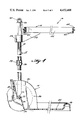
- FIG. 3 is a side elevational view of the cart showing the bag supporting structures in solid lines in their collapsed storage position and in phantom lines in their extended bag supporting positions;
- FIG. 4 is an enlarged fragmentary sectional view taken along the line 4--4 of FIG. 1;
- FIG. 5 is an enlarged fragmentary sectional view taken along the line 5--5 of FIG. 1;
- FIG. 6 is an enlarged fragmentary sectional view taken along the line 6--6 of FIG. 3;
- FIG. 7 is an enlarged fragmentary sectional view taken along the line 7--7 of FIG. 1.
- FIGS. 1-4 there is shown in FIGS. 1-4 thereof a cart, generally indicated at 10, which embodies the principles of the present invention.
- the cart 10 includes in general an upright tubular wheeled frame structure, generally indicated at 12, a platform structure 14 mounted on the lower portion of the wheeled frame structure 12 for pivotal movement between an extended bag supporting position, as shown in FIGS. 1 and 4, and a collapsed storage position, as shown in FIGS. 2 and 3, and an open bag mouth supporting structure, generally indicated at 16, mounted on the upper portion of the upright wheeled frame structure 12 for movement between an extended open bag mouth supporting position, as shown in FIGS. 1 and 4, and a collapsed storage position, as shown in FIGS. 2 and 3.
- the frame structure 12 is preferably formed of an elongated tube, preferably of metal, bent into an inverted U-shaped configuration so as to provide a pair of upright leg sections 18 integrally interconnected at their upper ends with a transversely horizontally extending bight section defining a handle 20.
- the lower free ends of the leg sections 18 are apertured to receive the ends of a transversely extending axle or wheel shaft 22 (see FIG. 4).
- the upright wheeled frame structure 12 also includes a pair of wheels 24 journaled on opposite end portions of the shaft 22.
- the frame structure 12 may also include an intermediate brace 26 which preferably is molded of plastic material, such as polypropylene or the like, to have a generally H-shaped cross-sectional configuration substantially throughout its length.
- an intermediate brace 26 which preferably is molded of plastic material, such as polypropylene or the like, to have a generally H-shaped cross-sectional configuration substantially throughout its length.
- C-shaped gripping elements 28 are rearwardly opening C-shaped gripping elements 28.
- the interior of the C of these gripping elements is configured to engage over and grip the forward intermediate portion of the tubular leg sections 18.
- the C extends arcuately a distance of approximately 270° so as to require a snapping action into gripping engagement with the tubular leg section whereby the ends of the brace are firmly gripped onto the leg sections. It will be understood, however, that the brace is capable of being moved along the longitudinal extent of the leg sections.
- the platform structure 14 is preferably of a unitary construction molded of a plastic material, such as polypropylene or other similar material.
- the platform structure consists essentially of two fender walls 30, a rear wall 32 and a platform wall 34.
- Each fender wall extends over the upper and forward periphery of an associated wheel 24 and downwardly and rearwardly over both sides of the associated wheel when the platform structure is in its extended position.
- Each fender wall 30 includes inner and outer side wall portions 36 and 38 which are apertured, as indicated at 40 in FIG. 4, to receive the associated end portion of the wheel shaft 22 therethrough.
- the outer extremities of the wheel shaft 22 are capped, as indicated at 42, to retain the same in assembled position. It will be noted that by virtue of the engagement of the wheel shaft 22 through the openings 40, the platform structure 14 is mounted for pivotal movement with respect to the frame structure 12 between the extended bag supporting position and collapsed storage position thereof.
- each fender wall 30 has integrally formed thereon a forwardly opening C-shaped element 44 which is of a construction similar to the C-shaped element 28 of the brace 26.
- the interior size of the C is such as to grippingly engage the adjacent rearward portion of the tubular leg sections 18 while the arcuate extent of the C is approximately 270° so as to grip the pipe sections with a snap action in response to the movement of the platform structure into its extended bag supporting position.
- the surface defining the forward open extent of the C-shaped elements 44 tapers inwardly toward the interior of the C-shaped elements so as to materially aid in the snap gripping action of the C-shaped elements in response to the aforesaid relative movement.
- each C-shaped element 44 will yield and release the grip on the associated leg section 18 when the platform structure 14 is moved in the opposite direction out of the bag supporting position, shown in FIGS. 1 and 4, toward the collapsed storage position, shown in FIGS. 2 and 3.
- the platform wall 34 is formed with an integral peripheral rim portion 46 which is preferably of inverted U-shaped cross-sectional configuration.
- the transversely outer portions of the inverted U-shaped rim 46 are formed with integral projections 48 which serve to engage the transversely inner portions of the tubular leg sections 18 as shown in FIG. 6 when the platform structure 14 is moved into its collapsed storage position, as shown in FIGS. 2 and 3, so as to releasably retain the same therein.
- the adjacent wall portion of the rim will deflect sufficient to enable the projections to be engaged with the tubular leg portions 18 and to be released therefrom.
- the rear wall 32 which extends transversely between the inner side wall portions 36 of the fender walls 30 includes an intermediate step portion 50 therein which engages over and in front of the central portion of the wheel shaft 22 when the platform structure is in its extended bag supporting position.
- an integral centrally located lug 52 is formed on the rearward central portion of the step 50 to insure retention of the step in engagement with the shaft. In this way the shaft serves to strengthen and support the central portion of the rear wall 32.
- the open bag mouth supporting structure 16 is, like the platform structure 14, preferably molded in a unitary construction from a plastic material, as for example, polypropylene.
- the structure 16 consists essentially of a hoop 54 having a pair of C-shaped elements 56 mounted, as by integral mounting arms 58, in transversely spaced relation along the rearward portion of the hoop 54 and a pair of handle engaging hook-shaped elements 60 formed integrally on the lower rearward portion of the hoop between the C-shaped elements 56.
- the C-shaped elements 56 are similar in configuration to the elements 28 and 44 previously described and both open transversely in the same direction so as to be moved into gripping engagement with the tubular leg sections 18 at positions adjacent the handle 20 in response to a transverse movement of the hoop in the open direction while the hoop is disposed in an extended horizontal position.
- the C-shaped elements 56 are releasable from gripping engagement with the tubular leg sections 18 in response to a movement of the hoop 54 transversely in the opposite direction.
- the hook-shaped elements 60 open downwardly when the hoop 54 is disposed in its extended horizontal position and engages the handle 20 so as to prevent downward movement of the hoop 54 when the C-shaped elements 56 are in gripping engagement with the leg sections 18.
- integral connections of the hook elements 60 and mounting arms 58 of the C-shaped elements 56 with the hoop 54 are along the lower surface thereof when the hoop is disposed in its extended horizontal position, thus providing access to the exterior periphery of the hoop from above throughout so as to permit the open mouth of a plastic bag to be extended through the hoop and over the same.
- an elastic band 62 is provided in order to retain the open bag mouth in this position.
- the band 62 is retained on the exterior periphery of the hoop 54 by a multiplicity of annularly spaced integral projections 64 extending outwardly from the upper and lower edges of the hoop in staggered relation with respect to one another.
- FIG. 1 illustrates the manner in which the cart 10 is used to support a plastic bag so that the interior can be filled through its open mouth with leaves or the like.
- the open mouth extends through the horizontally positioned hoop 54 and upwardly and over the exterior periphery thereof where it is retained by the elastic band 62.
- the bottom of the plastic bag rests upon the platform structure 14 with the fender walls 30 and rear wall 32 thereof serving with the platform wall 34 to support the bag bottom and to positively prevent the same from contacting the axle 22 and wheels 24.
- the arrangement is particularly efficient in that the weight of the contents of the bag can be concentrated near the wheels without danger of tearing the bag through contact with the wheels.
- the gripping action of the C-shaped elements 56 on the leg sections 18 is such as to provide the entire support for the open upper end of the bag.
- an important feature of the functioning of the C-shaped elements 56 is that the hoop is supported in any position of vertical adjustment along the length of the leg sections 18 so as to accommodate bags of different size. This adjustment can be readily accomplished manually by simply manually engaging the C-shaped elements and moving them along the length of the leg sections.
- the gripping action is such that a sliding movement can be accomplished as long as the moving force is applied directly on the C-shaped elements 56 in the direction of extent of the leg sections.
- the bag load supported by the hoop is transmitted to the C-shaped elements 56 in such a way as to cause them to cant or skew rather than to slide vertically.
- brace 26 is likewise universally movable along the leg sections to accommodate bags of different size.
- the operator simply effects a relative counterclockwise movement, as viewed in FIG. 4, of the platform structure 14 relative to the frame structure 12 which has the effect of releasing the gripping action of the C-shaped elements 44 from the leg sections 18 and finally engaging the projections 48 therewith when the platform structure 14 has been pivoted into its collapsed vertically extending position, as shown in FIGS. 2 and 3.
- the hoop structure 16 is moved from its extended open bag mouth supporting position by effecting a transverse horizontal movement of the hoop structure in a direction opposite from the direction in which the C-shaped elements 56 open.
- This movement which is accommodated by the hook elements 60 with respect to the handle 20, serves to disengage the C-shaped elements 56 from the leg portions 18, thus permitting the hoop 54 to be pivoted in a counterclockwise direction, as viewed in FIG. 4, about the axis of the handle with the hook elements 60 serving as the pivotal connection.
- the hook elements 60 serve to suspend the hoop 54 in a position below the handle 20.
- the cart is capable of being suspended from a vertical wall in such a way as to minimize the space required to store the same. While the pivotal movement of the open bag mouth supporting structure 16 into its storage position as described above is preferred, it will be understood that the open bag mouth supporting structure could simply be totally removed from engagement with the frame and independently suspended with the forward edge of the hoop disposed alongside the frame handle.
Abstract
Description
Claims (16)
Priority Applications (1)
| Application Number | Priority Date | Filing Date | Title |
|---|---|---|---|
| US06/416,064 US4452468A (en) | 1982-09-08 | 1982-09-08 | Cart with molded bag supporting structures |
Applications Claiming Priority (1)
| Application Number | Priority Date | Filing Date | Title |
|---|---|---|---|
| US06/416,064 US4452468A (en) | 1982-09-08 | 1982-09-08 | Cart with molded bag supporting structures |
Publications (1)
| Publication Number | Publication Date |
|---|---|
| US4452468A true US4452468A (en) | 1984-06-05 |
Family
ID=23648386
Family Applications (1)
| Application Number | Title | Priority Date | Filing Date |
|---|---|---|---|
| US06/416,064 Expired - Lifetime US4452468A (en) | 1982-09-08 | 1982-09-08 | Cart with molded bag supporting structures |
Country Status (1)
| Country | Link |
|---|---|
| US (1) | US4452468A (en) |
Cited By (42)
| Publication number | Priority date | Publication date | Assignee | Title |
|---|---|---|---|---|
| FR2584358A1 (en) * | 1985-07-03 | 1987-01-09 | Demnard Gilles | Barrow |
| US4887837A (en) * | 1987-06-04 | 1989-12-19 | Al-Mar Precision Co. | Carrier for use on beaches, etc. |
| US4889267A (en) * | 1988-05-02 | 1989-12-26 | Bolton David R | Cooler caddy for golf cart |
| US4917401A (en) * | 1987-12-25 | 1990-04-17 | Kobayashi Hansokiki Co., Ltd. | Parcel cart |
| US5069405A (en) * | 1990-03-19 | 1991-12-03 | Cornerstone Products, Inc. | Mobile leaf bag loading fixture |
| US5197754A (en) * | 1991-07-29 | 1993-03-30 | Ward Lyla B | Collapsible beach cart |
| WO1994013170A1 (en) * | 1992-12-15 | 1994-06-23 | Purdy Neat Things Company, Inc. | Wheeled luggage |
| US5340135A (en) * | 1993-12-21 | 1994-08-23 | Womberly Johnnie V | Hand truck for fishing equipment |
| EP0626300A1 (en) * | 1993-05-25 | 1994-11-30 | Claber S.P.A. | Cart for the collection of rubbish in general and its transportation over uneven terrain, particularly suitable for use in gardening |
| US5415420A (en) * | 1993-08-16 | 1995-05-16 | Koeller; James E. | Cart can retainer |
| US5445398A (en) * | 1994-03-02 | 1995-08-29 | Pierce; Patrick S. | Utility cart with vacuum adaptor |
| US5544910A (en) * | 1992-11-25 | 1996-08-13 | Products Finishing Corporation | Portable luggage cart |
| USD378455S (en) * | 1996-01-26 | 1997-03-11 | Wilson Alan E | Wheeled cart for supporting multiple articles |
| USD379016S (en) * | 1996-01-26 | 1997-04-29 | Wilson Alan E | Wheeled cart |
| USD383141S (en) * | 1995-07-12 | 1997-09-02 | Tom Martini | Roofing material applicator |
| US5671933A (en) * | 1995-09-14 | 1997-09-30 | Tucker; Ray D. | Utility cart |
| US5707030A (en) * | 1995-10-13 | 1998-01-13 | Claber S.P.A. | Waste-carrier trolley with a base in the form of a tray, more particularly for gardening |
| US5749588A (en) * | 1996-07-29 | 1998-05-12 | Harper Trucks, Inc. | Composite hand truck |
| US5752634A (en) * | 1996-09-30 | 1998-05-19 | Kortman; Larry P. | Bracket for attaching a container to a golf cart |
| US6135466A (en) * | 1997-12-09 | 2000-10-24 | Irwin; Lawrence F. | Transport dolly for lifting and transporting lavatory fixtures |
| US6330990B1 (en) * | 1999-11-01 | 2001-12-18 | Raymond Haubrich | Universal mechanical bag holder |
| US6367822B1 (en) * | 2000-07-11 | 2002-04-09 | William B. Hutchins | Bag expander |
| US6616153B1 (en) | 2001-05-30 | 2003-09-09 | Matre Design, Inc. | Plastic hand truck with folding metal platen |
| US6666465B2 (en) * | 2001-06-11 | 2003-12-23 | Alex Chan | Garden trolley |
| US20040051266A1 (en) * | 2002-09-12 | 2004-03-18 | Morrison Don H. | Carrying cart for trolling motor & battery |
| WO2006134392A2 (en) | 2005-06-17 | 2006-12-21 | Fripp Design Ltd | Gardening aid |
| US20070035098A1 (en) * | 2005-08-11 | 2007-02-15 | Creative Strategy Group, Inc. | Rolling system with handle |
| US20070176381A1 (en) * | 2004-03-23 | 2007-08-02 | 2Bmoved Holding B.V. | Wheeled device for bag-like container and method with regard to the device |
| US7458600B1 (en) * | 1998-12-09 | 2008-12-02 | Berke Joseph J | Cart and bag carrier |
| US20080309038A1 (en) * | 2007-06-14 | 2008-12-18 | James Gilligan | Trash bag holder and transporter |
| US7628406B1 (en) * | 2007-03-31 | 2009-12-08 | Thomas Charles M | Hand truck to transport horse related equipment |
| US8162349B1 (en) | 2008-12-18 | 2012-04-24 | Roselle Michael J | Collapsible carrier |
| US20120235387A1 (en) * | 2011-03-18 | 2012-09-20 | Bruce Robert S | Wheeled Cart for Transporting Outdoor Equipment |
| US20130334797A1 (en) * | 2008-02-07 | 2013-12-19 | Gerald Umbro | Wheeled container carrier |
| US8888054B1 (en) * | 2010-04-06 | 2014-11-18 | Per Anders Peterson | Secured bag forming and support apparatus |
| US9290194B1 (en) * | 2014-10-24 | 2016-03-22 | Maria C. Catinchi | Bag holder apparatus |
| USD779763S1 (en) * | 2015-09-16 | 2017-02-21 | Mischa Bishop | Cart |
| USD796770S1 (en) * | 2015-09-03 | 2017-09-05 | Ideal Warehouse Innovations, Inc. | Portable carrier |
| USD819291S1 (en) | 2016-05-27 | 2018-05-29 | Jean-Luc Turcotte | Bag supporting device |
| US9988172B2 (en) * | 2015-10-22 | 2018-06-05 | Nebojsa Ristoski | Bag holder and transport cart |
| USD851353S1 (en) * | 2015-03-03 | 2019-06-11 | Ideal Warehouse Innovations, Inc | Cartridge and cartridge assembly |
| US20220119056A1 (en) * | 2019-07-15 | 2022-04-21 | Yoav HIZMI | Multifunction garden cart |
Citations (11)
| Publication number | Priority date | Publication date | Assignee | Title |
|---|---|---|---|---|
| US1216941A (en) * | 1916-11-01 | 1917-02-20 | William Watson Camp | Bag-holder. |
| US2725153A (en) * | 1954-11-02 | 1955-11-29 | P B R Mfg Co | Hand truck |
| US2798651A (en) * | 1956-09-04 | 1957-07-09 | Wasyluk Joseph | Canopy carrier for strollers |
| US2950925A (en) * | 1957-08-26 | 1960-08-30 | Karl O Larson | Utility push cart |
| US3041026A (en) * | 1959-04-27 | 1962-06-26 | Earl F Wilson | Sack cart |
| US3754771A (en) * | 1971-11-26 | 1973-08-28 | P Shagoury | Bag holder |
| US3845968A (en) * | 1974-01-02 | 1974-11-05 | M Larson | Wheeled carrier for refuse containers |
| US3992034A (en) * | 1975-08-22 | 1976-11-16 | Smith Sr Harvey J | Multipurpose knockdown handcart |
| US3998476A (en) * | 1975-09-29 | 1976-12-21 | Kazmark Sr Eugene Anthony | Portable luggage carrier with telescoping handle |
| US4124185A (en) * | 1977-06-29 | 1978-11-07 | Preisinger Carl M | Bag holder |
| US4202521A (en) * | 1978-11-24 | 1980-05-13 | Harding Frank M | Combination bag holder and dolly |
-
1982
- 1982-09-08 US US06/416,064 patent/US4452468A/en not_active Expired - Lifetime
Patent Citations (11)
| Publication number | Priority date | Publication date | Assignee | Title |
|---|---|---|---|---|
| US1216941A (en) * | 1916-11-01 | 1917-02-20 | William Watson Camp | Bag-holder. |
| US2725153A (en) * | 1954-11-02 | 1955-11-29 | P B R Mfg Co | Hand truck |
| US2798651A (en) * | 1956-09-04 | 1957-07-09 | Wasyluk Joseph | Canopy carrier for strollers |
| US2950925A (en) * | 1957-08-26 | 1960-08-30 | Karl O Larson | Utility push cart |
| US3041026A (en) * | 1959-04-27 | 1962-06-26 | Earl F Wilson | Sack cart |
| US3754771A (en) * | 1971-11-26 | 1973-08-28 | P Shagoury | Bag holder |
| US3845968A (en) * | 1974-01-02 | 1974-11-05 | M Larson | Wheeled carrier for refuse containers |
| US3992034A (en) * | 1975-08-22 | 1976-11-16 | Smith Sr Harvey J | Multipurpose knockdown handcart |
| US3998476A (en) * | 1975-09-29 | 1976-12-21 | Kazmark Sr Eugene Anthony | Portable luggage carrier with telescoping handle |
| US4124185A (en) * | 1977-06-29 | 1978-11-07 | Preisinger Carl M | Bag holder |
| US4202521A (en) * | 1978-11-24 | 1980-05-13 | Harding Frank M | Combination bag holder and dolly |
Cited By (46)
| Publication number | Priority date | Publication date | Assignee | Title |
|---|---|---|---|---|
| FR2584358A1 (en) * | 1985-07-03 | 1987-01-09 | Demnard Gilles | Barrow |
| US4887837A (en) * | 1987-06-04 | 1989-12-19 | Al-Mar Precision Co. | Carrier for use on beaches, etc. |
| US4917401A (en) * | 1987-12-25 | 1990-04-17 | Kobayashi Hansokiki Co., Ltd. | Parcel cart |
| US4889267A (en) * | 1988-05-02 | 1989-12-26 | Bolton David R | Cooler caddy for golf cart |
| US5069405A (en) * | 1990-03-19 | 1991-12-03 | Cornerstone Products, Inc. | Mobile leaf bag loading fixture |
| US5197754A (en) * | 1991-07-29 | 1993-03-30 | Ward Lyla B | Collapsible beach cart |
| US5544910A (en) * | 1992-11-25 | 1996-08-13 | Products Finishing Corporation | Portable luggage cart |
| WO1994013170A1 (en) * | 1992-12-15 | 1994-06-23 | Purdy Neat Things Company, Inc. | Wheeled luggage |
| EP0626300A1 (en) * | 1993-05-25 | 1994-11-30 | Claber S.P.A. | Cart for the collection of rubbish in general and its transportation over uneven terrain, particularly suitable for use in gardening |
| US5415420A (en) * | 1993-08-16 | 1995-05-16 | Koeller; James E. | Cart can retainer |
| US5340135A (en) * | 1993-12-21 | 1994-08-23 | Womberly Johnnie V | Hand truck for fishing equipment |
| US5445398A (en) * | 1994-03-02 | 1995-08-29 | Pierce; Patrick S. | Utility cart with vacuum adaptor |
| USD383141S (en) * | 1995-07-12 | 1997-09-02 | Tom Martini | Roofing material applicator |
| US5671933A (en) * | 1995-09-14 | 1997-09-30 | Tucker; Ray D. | Utility cart |
| US5707030A (en) * | 1995-10-13 | 1998-01-13 | Claber S.P.A. | Waste-carrier trolley with a base in the form of a tray, more particularly for gardening |
| USD378455S (en) * | 1996-01-26 | 1997-03-11 | Wilson Alan E | Wheeled cart for supporting multiple articles |
| USD379016S (en) * | 1996-01-26 | 1997-04-29 | Wilson Alan E | Wheeled cart |
| US5749588A (en) * | 1996-07-29 | 1998-05-12 | Harper Trucks, Inc. | Composite hand truck |
| US5752634A (en) * | 1996-09-30 | 1998-05-19 | Kortman; Larry P. | Bracket for attaching a container to a golf cart |
| US6135466A (en) * | 1997-12-09 | 2000-10-24 | Irwin; Lawrence F. | Transport dolly for lifting and transporting lavatory fixtures |
| US7458600B1 (en) * | 1998-12-09 | 2008-12-02 | Berke Joseph J | Cart and bag carrier |
| US6330990B1 (en) * | 1999-11-01 | 2001-12-18 | Raymond Haubrich | Universal mechanical bag holder |
| US6367822B1 (en) * | 2000-07-11 | 2002-04-09 | William B. Hutchins | Bag expander |
| US6616153B1 (en) | 2001-05-30 | 2003-09-09 | Matre Design, Inc. | Plastic hand truck with folding metal platen |
| US6666465B2 (en) * | 2001-06-11 | 2003-12-23 | Alex Chan | Garden trolley |
| US6789807B2 (en) * | 2002-09-12 | 2004-09-14 | Don H. Morrison | Carrying cart for trolling motor and battery |
| US20040051266A1 (en) * | 2002-09-12 | 2004-03-18 | Morrison Don H. | Carrying cart for trolling motor & battery |
| US20070176381A1 (en) * | 2004-03-23 | 2007-08-02 | 2Bmoved Holding B.V. | Wheeled device for bag-like container and method with regard to the device |
| WO2006134392A2 (en) | 2005-06-17 | 2006-12-21 | Fripp Design Ltd | Gardening aid |
| US20070035098A1 (en) * | 2005-08-11 | 2007-02-15 | Creative Strategy Group, Inc. | Rolling system with handle |
| US7628406B1 (en) * | 2007-03-31 | 2009-12-08 | Thomas Charles M | Hand truck to transport horse related equipment |
| US20080309038A1 (en) * | 2007-06-14 | 2008-12-18 | James Gilligan | Trash bag holder and transporter |
| US8789836B2 (en) * | 2008-02-07 | 2014-07-29 | Gerald Umbro | Wheeled container carrier |
| US20130334797A1 (en) * | 2008-02-07 | 2013-12-19 | Gerald Umbro | Wheeled container carrier |
| US8162349B1 (en) | 2008-12-18 | 2012-04-24 | Roselle Michael J | Collapsible carrier |
| US8888054B1 (en) * | 2010-04-06 | 2014-11-18 | Per Anders Peterson | Secured bag forming and support apparatus |
| US8317219B2 (en) * | 2011-03-18 | 2012-11-27 | Robert S Bruce | Wheeled cart for transporting outdoor equipment |
| US20120235387A1 (en) * | 2011-03-18 | 2012-09-20 | Bruce Robert S | Wheeled Cart for Transporting Outdoor Equipment |
| US9290194B1 (en) * | 2014-10-24 | 2016-03-22 | Maria C. Catinchi | Bag holder apparatus |
| USD835377S1 (en) | 2015-03-03 | 2018-12-04 | Ideal Warehouse Innovations, Inc. | Portable carrier |
| USD851353S1 (en) * | 2015-03-03 | 2019-06-11 | Ideal Warehouse Innovations, Inc | Cartridge and cartridge assembly |
| USD796770S1 (en) * | 2015-09-03 | 2017-09-05 | Ideal Warehouse Innovations, Inc. | Portable carrier |
| USD779763S1 (en) * | 2015-09-16 | 2017-02-21 | Mischa Bishop | Cart |
| US9988172B2 (en) * | 2015-10-22 | 2018-06-05 | Nebojsa Ristoski | Bag holder and transport cart |
| USD819291S1 (en) | 2016-05-27 | 2018-05-29 | Jean-Luc Turcotte | Bag supporting device |
| US20220119056A1 (en) * | 2019-07-15 | 2022-04-21 | Yoav HIZMI | Multifunction garden cart |
Similar Documents
| Publication | Publication Date | Title |
|---|---|---|
| US4452468A (en) | Cart with molded bag supporting structures | |
| US5048778A (en) | Trash bag apparatus | |
| US5209517A (en) | Wheeled vehicle | |
| US6131861A (en) | Bag holder | |
| US4238868A (en) | Refuse bag holder | |
| US3845968A (en) | Wheeled carrier for refuse containers | |
| GB2057368A (en) | Hand truck | |
| US6070906A (en) | Wheeled ski and equipment carrying device | |
| WO1984002638A1 (en) | Steering and support handle for wheeled luggage | |
| US3091342A (en) | Receptacle support and holder | |
| US5193770A (en) | Bag holder | |
| US6126183A (en) | Foldable cart with automatic bag control | |
| US3797847A (en) | Collapsible and portable cart for flexible trash | |
| US2477294A (en) | Hand truck | |
| US3950004A (en) | Arrangement for garden barrows | |
| US4138139A (en) | Collapsible trash carrier | |
| US2802673A (en) | Portable trash and garbage can holder | |
| US2684796A (en) | Combination car top carrier and boat | |
| US4136889A (en) | Collapsible trolley | |
| US3749414A (en) | Refuse can holder | |
| US1744414A (en) | Golf-bag attachment | |
| WO2011051721A1 (en) | Collapsible frame | |
| US4061360A (en) | Collapsible golf bag cart | |
| JPH09503149A (en) | Baggage case | |
| US5083731A (en) | Portable holder for refuse bag |
Legal Events
| Date | Code | Title | Description |
|---|---|---|---|
| AS | Assignment |
Owner name: O. AMES CO., PARKERSBURG, WEST VA A CORP. OF VA Free format text: ASSIGNMENT OF ASSIGNORS INTEREST.;ASSIGNORS:EADS, HAROLD O.;FOWLER, RONALD R.;ADAMS, DANNY C.;REEL/FRAME:004043/0120 Effective date: 19820826 Owner name: O. AMES CO., WEST VIRGINIA Free format text: ASSIGNMENT OF ASSIGNORS INTEREST;ASSIGNORS:EADS, HAROLD O.;FOWLER, RONALD R.;ADAMS, DANNY C.;REEL/FRAME:004043/0120 Effective date: 19820826 |
|
| STCF | Information on status: patent grant |
Free format text: PATENTED CASE |
|
| FEPP | Fee payment procedure |
Free format text: PAYOR NUMBER ASSIGNED (ORIGINAL EVENT CODE: ASPN); ENTITY STATUS OF PATENT OWNER: LARGE ENTITY |
|
| FPAY | Fee payment |
Year of fee payment: 4 |
|
| FPAY | Fee payment |
Year of fee payment: 8 |
|
| FPAY | Fee payment |
Year of fee payment: 12 |
|
| AS | Assignment |
Owner name: WILMINGTON TRUST COMPANY, DELAWARE Free format text: SECURITY AGREEMENT;ASSIGNORS:AMES TRUE TEMPER PROPERTIES, INC;AMES TRUE TEMPER, INC;ARCHITECTURAL AREA LIGHTING, INC.;AND OTHERS;REEL/FRAME:011731/0097 Effective date: 20010430 |
|
| AS | Assignment |
Owner name: AMES TRUE TEMPER PROPERTIES, INC., PENNSYLVANIA Free format text: RELEASE OF SECURITY;ASSIGNORS:WILMINGTON TRUST COMPANY;VANASKY, DAVID A.;REEL/FRAME:012483/0690 Effective date: 20020104 Owner name: AMES TRUE TEMPER, INC., PENNSYLVANIA Free format text: RELEASE OF SECURITY;ASSIGNORS:WILMINGTON TRUST COMPANY;VANASKY, DAVID A.;REEL/FRAME:012483/0690 Effective date: 20020104 Owner name: IXL MANUFACTURING COMPANY, INC., MISSOURI Free format text: RELEASE OF SECURITY;ASSIGNORS:WILMINGTON TRUST COMPANY;VANASKY, DAVID A.;REEL/FRAME:012483/0690 Effective date: 20020104 Owner name: FOOTHILL CAPITAL CORPORATION, CALIFORNIA Free format text: SECURITY AGREEMENT;ASSIGNORS:AMES TRUE TEMPER, INC.;IXL MANUFACTURING COMPANY, INC.;AMES TRUE TEMPER PROPERTIES, INC.;REEL/FRAME:012483/0769 Effective date: 20020114 |
|
| AS | Assignment |
Owner name: AMES TRUE TEMPER PROPERTIES, INC., PENNSYLVANIA Free format text: RELEASE OF SECURITY INTEREST;ASSIGNOR:WELLS FARGO FOOTHILL, INC. (N/K/A WELLS FARGO FOOTHILL, INC.);REEL/FRAME:016489/0801 Effective date: 20040625 Owner name: IXL MANUFACTURING COMPANY, INC., PENNSYLVANIA Free format text: RELEASE OF SECURITY INTEREST;ASSIGNOR:WELLS FARGO FOOTHILL, INC. (N/K/A WELLS FARGO FOOTHILL, INC.);REEL/FRAME:016489/0801 Effective date: 20040625 Owner name: AMES PLANTER, INC., PENNSYLVANIA Free format text: RELEASE OF SECURITY INTEREST;ASSIGNOR:WELLS FARGO FOOTHILL, INC. (N/K/A WELLS FARGO FOOTHILL, INC.);REEL/FRAME:016489/0801 Effective date: 20040625 Owner name: AMES TRUE TEMPER, PENNSYLVANIA Free format text: RELEASE OF SECURITY INTEREST;ASSIGNOR:WELLS FARGO FOOTHILL, INC. (N/K/A WELLS FARGO FOOTHILL, INC.);REEL/FRAME:016489/0801 Effective date: 20040625 |