US4450938A - Air line lubricator - Google Patents
Air line lubricator Download PDFInfo
- Publication number
- US4450938A US4450938A US06/451,027 US45102782A US4450938A US 4450938 A US4450938 A US 4450938A US 45102782 A US45102782 A US 45102782A US 4450938 A US4450938 A US 4450938A
- Authority
- US
- United States
- Prior art keywords
- air line
- piston
- chamber
- section
- bore
- Prior art date
- Legal status (The legal status is an assumption and is not a legal conclusion. Google has not performed a legal analysis and makes no representation as to the accuracy of the status listed.)
- Expired - Lifetime
Links
- 239000000314 lubricant Substances 0.000 claims description 12
- 238000004891 communication Methods 0.000 claims description 4
- 238000007599 discharging Methods 0.000 claims 1
- 239000003921 oil Substances 0.000 abstract description 19
- 239000010687 lubricating oil Substances 0.000 abstract description 6
- 230000037452 priming Effects 0.000 abstract description 3
- 238000010276 construction Methods 0.000 abstract description 2
- 230000000694 effects Effects 0.000 description 3
- 230000006835 compression Effects 0.000 description 2
- 238000007906 compression Methods 0.000 description 2
- 230000008878 coupling Effects 0.000 description 2
- 238000010168 coupling process Methods 0.000 description 2
- 238000005859 coupling reaction Methods 0.000 description 2
- 238000005086 pumping Methods 0.000 description 2
- 230000015572 biosynthetic process Effects 0.000 description 1
- 238000006073 displacement reaction Methods 0.000 description 1
- 238000012986 modification Methods 0.000 description 1
- 230000004048 modification Effects 0.000 description 1
- 230000002093 peripheral effect Effects 0.000 description 1
- 230000036316 preload Effects 0.000 description 1
- 230000002035 prolonged effect Effects 0.000 description 1
- 230000000717 retained effect Effects 0.000 description 1
- 230000006641 stabilisation Effects 0.000 description 1
- 238000011105 stabilization Methods 0.000 description 1
- 239000007858 starting material Substances 0.000 description 1
Images
Classifications
-
- F—MECHANICAL ENGINEERING; LIGHTING; HEATING; WEAPONS; BLASTING
- F16—ENGINEERING ELEMENTS AND UNITS; GENERAL MEASURES FOR PRODUCING AND MAINTAINING EFFECTIVE FUNCTIONING OF MACHINES OR INSTALLATIONS; THERMAL INSULATION IN GENERAL
- F16N—LUBRICATING
- F16N13/00—Lubricating-pumps
- F16N13/02—Lubricating-pumps with reciprocating piston
- F16N13/06—Actuation of lubricating-pumps
- F16N13/16—Actuation of lubricating-pumps with fluid drive
-
- F—MECHANICAL ENGINEERING; LIGHTING; HEATING; WEAPONS; BLASTING
- F16—ENGINEERING ELEMENTS AND UNITS; GENERAL MEASURES FOR PRODUCING AND MAINTAINING EFFECTIVE FUNCTIONING OF MACHINES OR INSTALLATIONS; THERMAL INSULATION IN GENERAL
- F16N—LUBRICATING
- F16N7/00—Arrangements for supplying oil or unspecified lubricant from a stationary reservoir or the equivalent in or on the machine or member to be lubricated
- F16N7/30—Arrangements for supplying oil or unspecified lubricant from a stationary reservoir or the equivalent in or on the machine or member to be lubricated the oil being fed or carried along by another fluid
Definitions
- Air line lubricators for air motors are generally categorized as continuous or one shot lubricators.
- Continuous lubricators as the name implies, continuously supply a small amount of lubricating oil to the air line regardless of demand. These lubricators are generally satisfactory where the demand for air is relatively constant and the using devices are relatively similar. These lubricators often restrict the air flow.
- the one shot lubricator was developed to accomodate sporadic or heavy intermittent demands and, as the name implies, generally inject a particular quantity of lubricating oil into the air line once the air line is pressurized. These devices are commonly of the in-line type with small or limited reservoir capacity which poorly distribute the oil during a continuous run.
- the object of the present invention is to provide a compact air motor lubricator which may be attached directly to an air line and operate with a remote oil supply reservoir of sufficient capacity to avoid the necessity of constant or daily refilling.
- a further object of the invention is to provide an air motor lubricator which is inexpensive and reliable in operation.
- a further object is to provide an air motor lubricator which is self priming, load responsive, and injects the lubricating oil directly into the air stream for a prolonged period.
- Yet a further object is to provide an air motor lubricator which has only one check valve and one moving piston. It is also an object of this invention to provide an air motor lubricator which utilizes a unique U-seal in combination with a bevelled piston to accomplish unidirectional oil flow and recharging.
- an air line lubricator comprising a hollow body having two different cross sectioned areas, a stepped sealed piston movable in the body to form three variable chambers therein in conjunction with the body, the first variable chamber towards one end of said body having the greater cross section being in communication with the air line, the second of the variable chambers intermediate the first chamber and the third chamber formed by the smaller cross section of the piston in the greater cross section of the body toward its other end and the smaller cross section of said piston, the third chamber being in communication with a lubricant supply, a directional seal coacting with the smaller cross section of the body and the smaller cross section of the piston to allow lubricant to pass from the second chamber to the third chamber when the piston moves toward the one end, a bore in said piston therethrough from the one end of the piston to the other end of the piston communicating between the first and the third chambers, a check valve in the bore to permit lubricant flow only from the third chamber to the first when the piston moves towards the other end of the body, and
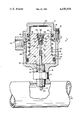
- FIG. 1 shows a partial cross section view in elevation of the air line lubricator according to the present invention.
- a lubricator as shown in FIG. 1 and generally designated by reference numeral 1, is comprised of a cup-like cylindrical body 2 to which is attached an inverted cup-like end cap 3 by means of conventional cap screws 4 or the like.
- the cap screws 4 are shown inserted in screw bores 5 of the cup body 2.
- the cap 3 has a horizontal flange 12 through which the cap screws 4 are inserted.
- the cap screws 4 are conveniently located around the circumference of the horizontal flange 12.
- a vertical flange 14 extends into the interior of the cup body 2 and is provided with a cap seal o-ring 11 to form a seal chamber within the cup body 2 and end cap 3.
- a stepped piston 30 Disposed within the cavity is a stepped piston 30 having its major diameter 37 in proximate contact with the cup body 2.
- the piston 30 is capable of axial displacement (vertical, as shown in FIG. 1).
- An o-ring seal 31 in a groove in the major diameter 37 effects a positive seal.
- the piston 30 has an intermediate diameter 38 which permits formation of an oil preload chamber or intermediate chamber 26.
- the piston 30 also has a minor diameter 39 which cooperates with the interior diameter of the cap 3 to form an oil pressurizing or pumping chamber 25.
- the minor diameter 39 of the piston 30 is of sufficient length to communicate with the intermediate chamber 26. The minor diameter may in fact be carried all the way to land 33 without materially effecting operation apart from spring stabilization.
- a spring 32 biases the piston 30 downward as shown in FIG. 1 and is disposed between the land 33 formed by the major diameter 37 and the intermediate diameter 38 and a land 16 formed on vertical flange 14. Land 16 also serves to position a U-shaped check seal 35, the function of which will be later described.
- the cup body 2 is provided with a threaded oil supply connection 15.
- a pipe or hose leading to a reservoir of sufficient capacity would be connected to the oil supply connection in operation and is not shown.
- Oil from the reservoir would enter intermediate chamber 26 through oil inlet 17 during normal operation.
- Oil entering intermediate chamber 26 may pass land 16 and pass check seal 35 with the position of the piston shown in FIG. 1. Clearance between the check seal 35 and the piston 30 is provided by a bevel 40 at the top of the piston.
- an orifice plate 55 Shown inserted in the top of piston 30 in a stepped counter bore 45 is an orifice plate 55 which is retained in the stepped counter bore 45 by means of a snap ring 56 and is sealed against peripheral flow by means of orifice o-ring seal 57.
- the orifice plate 55 is provided with a metering orifice 60 which controls the flow rate of lubricant.
- a ball check 50 cooperates with a seat 58 in the orifice plate 55 to permit lubricant flow only in the vertically downward direction as shown in FIG. 1.
- a ball check guide 51 and ball check spring 52 are shown disposed in the stepped counter bore 45 to urge the ball check 50 towards the seat 58.
- a discharge bore 65 extends from the stepped counter bore 45 through piston 30.
- a discharge tube 61 which is inserted in discharge bore 65 further extends the discharge bore through the bottom of the cup body 2 and neck 6 and into the interior of an air line 70.
- the lubricator 1 is shown connected to the air line 70 by means of a male connecting coupling 7 having a pipe thread 8 on one end connected to the air pipe and a straight thread 9 on its other end connected to the cup body 2 at the neck 6. Leakage past thread 9 and the neck 6 of the cup body 2 is prevented by o-ring seal 10 in a conventional manner.
- the male connecting coupling 7 is provided with a bore 21 which communicates between the interior of the air line 70 and air pressure chamber 27 formed between the piston 30 and the bottom of the cup body 2.
- Discharge tube 61 passes through the center of bore 21 with sufficient diameteral clearance to form a concentric air flow path 20. Through this path, air pressure in air line 70 is communicated to air pressure chamber 27. The discharge tube extends into the air line beyond the air line wall. This permits deposit of oil directly into the air stream without the surface effect of the air line wall. In addition, since the discharge tube moves with the piston it is less likely to become clogged or form a blockage in the air line.
- lubricating oil enters intermediate chamber 26 from the reservoir through oil inlet 17. Air flows through concentric path 20 to pressurize air chamber 27 thereby causing piston 30 to be displaced vertically upwards as shown in FIG. 1. Once the piston 30 has moved sufficiently to permit the bevel 40 to pass U-shaped seal 35, it should be obvious to one skilled in the art that chamber 25 will become pressurized and its oil contents forced through orifice 60, past check valve 50, through discharge bore 65 and the interior of discharge tube 61 into the air line 70.
- the orifice might be sized to provide forty seconds worth of oil discharge.
- the size of the orifice controls the discharge timing in cooperation with the air pressure in the air line.
- check seal 35 acts as a check valve and seal to provide a positive pumping action for the lubricating oil. It should be understood that although the check seal has been described as a U it may be V, Y, or chevron shaped or any other directional seal configuration allowing preferred one way flow. This makes the device according to the present invention self priming without the need for a separate check valve and associated porting.
- the resulting device as can be appreciated by one skilled in the art, is extremely simple, reliable, and readily adapatable by means of changing the size of orifice 60 to accomodate a wide range of oil flow and time demands.
Landscapes
- Engineering & Computer Science (AREA)
- General Engineering & Computer Science (AREA)
- Mechanical Engineering (AREA)
- Chemical & Material Sciences (AREA)
- Combustion & Propulsion (AREA)
- Oil, Petroleum & Natural Gas (AREA)
- Supply Devices, Intensifiers, Converters, And Telemotors (AREA)
Abstract
Description
Claims (9)
Priority Applications (1)
| Application Number | Priority Date | Filing Date | Title |
|---|---|---|---|
| US06/451,027 US4450938A (en) | 1982-12-20 | 1982-12-20 | Air line lubricator |
Applications Claiming Priority (1)
| Application Number | Priority Date | Filing Date | Title |
|---|---|---|---|
| US06/451,027 US4450938A (en) | 1982-12-20 | 1982-12-20 | Air line lubricator |
Publications (1)
| Publication Number | Publication Date |
|---|---|
| US4450938A true US4450938A (en) | 1984-05-29 |
Family
ID=23790512
Family Applications (1)
| Application Number | Title | Priority Date | Filing Date |
|---|---|---|---|
| US06/451,027 Expired - Lifetime US4450938A (en) | 1982-12-20 | 1982-12-20 | Air line lubricator |
Country Status (1)
| Country | Link |
|---|---|
| US (1) | US4450938A (en) |
Cited By (10)
| Publication number | Priority date | Publication date | Assignee | Title |
|---|---|---|---|---|
| US4598796A (en) * | 1985-02-22 | 1986-07-08 | Ingersoll-Rand Company | Lubricator |
| US5209098A (en) * | 1987-10-05 | 1993-05-11 | Reynolds Metals Company | Method and apparatus for forming can ends |
| US5331836A (en) * | 1987-10-05 | 1994-07-26 | Reynolds Metals Company | Method and apparatus for forming can ends |
| US5638920A (en) * | 1995-08-14 | 1997-06-17 | Oil-Rite Corporation | Air tool lubricator |
| US5961299A (en) * | 1997-06-16 | 1999-10-05 | Oil-Rite Corporation | Fluid injector pump with interchangeable reservoir |
| US5984652A (en) | 1997-06-17 | 1999-11-16 | Oil-Rite Corporation | Single-piece piston with central bore for use in a pneumatically-activated pump |
| US6071097A (en) * | 1997-08-29 | 2000-06-06 | Oil-Rite Corporation | Single-piece piston for use in a pneumatically-activated pump |
| US6659229B2 (en) * | 2001-05-09 | 2003-12-09 | Michael V. Rzeppa | Pneumatic in-line lubricator |
| WO2009033323A1 (en) * | 2007-09-13 | 2009-03-19 | Norgren, Inc. | Lubricating sight dome and method of operating the sight dome |
| CZ305091B6 (en) * | 2012-07-24 | 2015-04-29 | Emil Brabec | Liquid dosing apparatus, particularly lubricant dosing apparatus of total loss lubrication central systems |
Citations (9)
| Publication number | Priority date | Publication date | Assignee | Title |
|---|---|---|---|---|
| US458450A (en) * | 1891-08-25 | Lubricator | ||
| US1548869A (en) * | 1924-03-18 | 1925-08-11 | John N Clore | Lubricating device |
| US1606758A (en) * | 1925-10-10 | 1926-11-16 | Nathan Mfg Co | Control device for lubricating apparatus |
| US3209956A (en) * | 1964-08-24 | 1965-10-05 | Walker Mfg Co | Metering dispenser operated by the pressure of material dispensed |
| US3693757A (en) * | 1970-08-03 | 1972-09-26 | Mccord Corp | Lubricating apparatus |
| US3837431A (en) * | 1972-09-11 | 1974-09-24 | Murphy Ind Inc | Pulsed metering lubricator |
| US4105095A (en) * | 1977-05-31 | 1978-08-08 | Master Pneumatic-Detroit, Inc. | Injection lubricating apparatus |
| US4125176A (en) * | 1977-07-21 | 1978-11-14 | Master Pneumatic-Detroit, Inc. | Injection type lubricating apparatus |
| US4332309A (en) * | 1979-08-31 | 1982-06-01 | Arnold Bereit | Apparatus for the atomization of oil in a compressed air line |
-
1982
- 1982-12-20 US US06/451,027 patent/US4450938A/en not_active Expired - Lifetime
Patent Citations (9)
| Publication number | Priority date | Publication date | Assignee | Title |
|---|---|---|---|---|
| US458450A (en) * | 1891-08-25 | Lubricator | ||
| US1548869A (en) * | 1924-03-18 | 1925-08-11 | John N Clore | Lubricating device |
| US1606758A (en) * | 1925-10-10 | 1926-11-16 | Nathan Mfg Co | Control device for lubricating apparatus |
| US3209956A (en) * | 1964-08-24 | 1965-10-05 | Walker Mfg Co | Metering dispenser operated by the pressure of material dispensed |
| US3693757A (en) * | 1970-08-03 | 1972-09-26 | Mccord Corp | Lubricating apparatus |
| US3837431A (en) * | 1972-09-11 | 1974-09-24 | Murphy Ind Inc | Pulsed metering lubricator |
| US4105095A (en) * | 1977-05-31 | 1978-08-08 | Master Pneumatic-Detroit, Inc. | Injection lubricating apparatus |
| US4125176A (en) * | 1977-07-21 | 1978-11-14 | Master Pneumatic-Detroit, Inc. | Injection type lubricating apparatus |
| US4332309A (en) * | 1979-08-31 | 1982-06-01 | Arnold Bereit | Apparatus for the atomization of oil in a compressed air line |
Cited By (12)
| Publication number | Priority date | Publication date | Assignee | Title |
|---|---|---|---|---|
| US4598796A (en) * | 1985-02-22 | 1986-07-08 | Ingersoll-Rand Company | Lubricator |
| DE3605510A1 (en) * | 1985-02-22 | 1986-08-28 | Ingersoll-Rand Co., Woodcliff Lake, N.J. | LUBRICATION DEVICE |
| FR2578027A1 (en) * | 1985-02-22 | 1986-08-29 | Ingersoll Rand Co | GREASER FOR MACHINE |
| US5209098A (en) * | 1987-10-05 | 1993-05-11 | Reynolds Metals Company | Method and apparatus for forming can ends |
| US5331836A (en) * | 1987-10-05 | 1994-07-26 | Reynolds Metals Company | Method and apparatus for forming can ends |
| US5638920A (en) * | 1995-08-14 | 1997-06-17 | Oil-Rite Corporation | Air tool lubricator |
| US5961299A (en) * | 1997-06-16 | 1999-10-05 | Oil-Rite Corporation | Fluid injector pump with interchangeable reservoir |
| US5984652A (en) | 1997-06-17 | 1999-11-16 | Oil-Rite Corporation | Single-piece piston with central bore for use in a pneumatically-activated pump |
| US6071097A (en) * | 1997-08-29 | 2000-06-06 | Oil-Rite Corporation | Single-piece piston for use in a pneumatically-activated pump |
| US6659229B2 (en) * | 2001-05-09 | 2003-12-09 | Michael V. Rzeppa | Pneumatic in-line lubricator |
| WO2009033323A1 (en) * | 2007-09-13 | 2009-03-19 | Norgren, Inc. | Lubricating sight dome and method of operating the sight dome |
| CZ305091B6 (en) * | 2012-07-24 | 2015-04-29 | Emil Brabec | Liquid dosing apparatus, particularly lubricant dosing apparatus of total loss lubrication central systems |
Similar Documents
| Publication | Publication Date | Title |
|---|---|---|
| US3209956A (en) | Metering dispenser operated by the pressure of material dispensed | |
| US3514017A (en) | Pressure regulating structure for piston pump | |
| US4450938A (en) | Air line lubricator | |
| US4004717A (en) | Pressure fed liquid dispenser | |
| US5632613A (en) | Lubricating device for horizontal type hermetic compressor | |
| CA1299536C (en) | Water jet injection device for use with dispensers for producing and dispensing beverages mixed of fruit syrup or concentrate and water | |
| US3888420A (en) | Positive-displacement mist lubricator | |
| US9388941B2 (en) | Compact lubricant injector and injector system | |
| US4200231A (en) | Fuel injector nozzle | |
| US3495544A (en) | Hydraulic system | |
| EP0202464A1 (en) | Device for spraying liquid | |
| EP3652479A1 (en) | Lubricant injector | |
| US3572469A (en) | Air line lubricating device | |
| US4598796A (en) | Lubricator | |
| EP0058688A1 (en) | Fluid flow control device | |
| US5984652A (en) | Single-piece piston with central bore for use in a pneumatically-activated pump | |
| JPS6259989B2 (en) | ||
| US5161645A (en) | Lubricator connected to a pressure fluid line | |
| EP0686434A2 (en) | Pump of simplified structure, for delivering pressurized fluids | |
| JPS6136876Y2 (en) | ||
| SU1009861A1 (en) | Device for lubricating locomotive wheel pair ribs | |
| CN1082168C (en) | Quantitative gas/liquid ejector | |
| US3807424A (en) | Valve | |
| US10875043B1 (en) | Lotion pump | |
| SU1192896A1 (en) | Arrangement for lubricating dies |
Legal Events
| Date | Code | Title | Description |
|---|---|---|---|
| AS | Assignment |
Owner name: INGERSOLL-RAND COMPANY, WOODCLIFF LAKE, N.J. 07675 Free format text: ASSIGNMENT OF ASSIGNORS INTEREST.;ASSIGNORS:DAVENPORT, HENRY A.;BARROWS, ROBERT E.;REEL/FRAME:004078/0866 Effective date: 19821124 |
|
| STCF | Information on status: patent grant |
Free format text: PATENTED CASE |
|
| FPAY | Fee payment |
Year of fee payment: 4 |
|
| FEPP | Fee payment procedure |
Free format text: PAYOR NUMBER ASSIGNED (ORIGINAL EVENT CODE: ASPN); ENTITY STATUS OF PATENT OWNER: LARGE ENTITY |
|
| FPAY | Fee payment |
Year of fee payment: 8 |
|
| FPAY | Fee payment |
Year of fee payment: 12 |