US4449908A - Dough pump - Google Patents
Dough pump Download PDFInfo
- Publication number
- US4449908A US4449908A US06/251,261 US25126181A US4449908A US 4449908 A US4449908 A US 4449908A US 25126181 A US25126181 A US 25126181A US 4449908 A US4449908 A US 4449908A
- Authority
- US
- United States
- Prior art keywords
- dough
- screw
- discharge conduit
- screw conveyor
- hopper
- Prior art date
- Legal status (The legal status is an assumption and is not a legal conclusion. Google has not performed a legal analysis and makes no representation as to the accuracy of the status listed.)
- Expired - Lifetime
Links
Images


Classifications
-
- A—HUMAN NECESSITIES
- A21—BAKING; EDIBLE DOUGHS
- A21C—MACHINES OR EQUIPMENT FOR MAKING OR PROCESSING DOUGHS; HANDLING BAKED ARTICLES MADE FROM DOUGH
- A21C1/00—Mixing or kneading machines for the preparation of dough
- A21C1/06—Mixing or kneading machines for the preparation of dough with horizontally-mounted mixing or kneading tools; Worm or screw mixers
-
- A—HUMAN NECESSITIES
- A21—BAKING; EDIBLE DOUGHS
- A21C—MACHINES OR EQUIPMENT FOR MAKING OR PROCESSING DOUGHS; HANDLING BAKED ARTICLES MADE FROM DOUGH
- A21C11/00—Other machines for forming the dough into its final shape before cooking or baking
- A21C11/16—Extruding machines
- A21C11/20—Extruding machines with worms
Definitions
- the invention disclosed herein relates to a method and apparatus for dispensing dough and the like which is received in a batch from a mixer and which is to be transported in smaller quantities to a subsequent work station such as to a dough divider of the type used to form the dough into biscuits.
- the dough tends to rise so that it becomes less dense and occupies a larger volume per unit of weight.
- the last portion of a batch of dough that is waiting to be divided is likely to be less dense than the first portion. Since the equipment used for dividing dough functions to divide the dough into uniform volumes, the dividing equipment will continue to form the biscuits, buns, etc. with the same volume but with less weight of dough as the dough from the batch rises, causing the subsequent products to be different from those products made from the first dough taken from the batch. As this happens, the dough divider operator usually attempts to compensate for the less dense dough by adjusting the divider to cause the biscuits, buns, etc. to be formed in larger volumes but of the same weight.
- the present invention comprises a dough dispensing system wherein a batch of dough and the like is received from a dough mixer in a hopper and the dough is progressively dispensed from the batch or mass of dough to a subsequent work station such as to a dough divider.
- the dough is worked as it is dispensed and the gases emanating from the dough are removed from the dough as the dough is worked, thereby maintaining and restoring the dough approximately to its original density as when received from the dough mixer.
- a screw conveyor comprising a pair of interference helical screw conveyor elements is located at the bottom of a hopper which receives the batch of dough from the dough mixer, and the screw conveyor is shaped so as to slice the dough from the mass of dough in the hopper, substantially without tearing the dough, and to transport the dough through a discharge conduit.
- the helical conveyor elements are formed in the discharge conduit so as to positively displace the dough through the discharge conduit and to divide the dough into small batches which are individually worked and degased as they are moved through the discharge conduit to a discharge nozzle.
- the discharge nozzle creates back pressure in the discharge conduit, causing a substantial portion of the gases about the batches of dough in the screw conveyor to be vented through a small vent port to the atmosphere, so that the dough being discharged from the nozzle is of a consistency and density approximately the same as when discharged from the dough mixer.
- the screw conveyor at the bottom of the hopper tends to fill its cavities at the rear of the batch of dough and the dough is moved in the cavities across the bottom of the batch to the discharge conduit. This results in the dough being fed first from the rear of the batch through a tunnel formed beneath the rest of the batch.
- An example of this is when it is desirable to add to the fresh dough the scrap dough from a dough shaping process in which dough extruded from the hopper is formed in a desired shape by cutting away some of the dough.
- the scrap dough from the dough shaping process is fed to the rear of the screw conveyor elements so that it immediately enters the screw conveyor. As the scrap dough moves with the screw conveyor beneath the fresh dough, the fresh dough fills in the remaining open space in the screw conveyor.
- Another object of this invention is to provide a dough pump method and apparatus which is inexpensive to construct and to maintain and which dispenses dough on a progressive basis from a large mass of dough at a desired density.
- Another object of this invention is to provide a dough pump method and apparatus wherein the dough is sliced from a large mass of dough, worked, degased and dispensed at a desired density.
- Another object of this invention is to provide a dough dispensing system which blends fresh dough with an additive such as scrap dough and which dispenses the combination at a desired density.
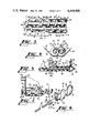
- FIG. 1 is a perspective illustration of the dough pump.
- FIG. 2 is a detail perspective illustration of the screw conveyor of the dough pump.
- FIG. 3 is a top view of the screw conveyor, showing a portion of the screw conveyor that extends through the bottom of the hopper and the portion of the screw conveyor that extends through the discharge conduit.
- FIG. 4 is a detail end view of the screw conveyor in the lower portion of the hopper.
- FIG. 5 is a side cross-sectional view of a portion of the screw conveyor, showing a portion of the hopper and the discharge conduit.
- FIG. 6 is an exploded perspective illustration of a portion of the screw conveyor, showing the manner in which the elements of the screw conveyor are connected together.
- FIG. 7 is a detail side cross-sectional view of the hopper showing the screw conveyor and the vent pump.
- FIG. 8 is a partial perspective illustration of the dough pump hopper, showing the scrap chute mounted over the screw conveyor at the rear of the hopper.
- FIG. 1 illustrates dough pump 10 which is usually placed beneath a dough mixer (not shown) and which dispenses dough for delivery to a subsequent work station, such as to a dough divider (not shown).
- the dough pump can dispense directly to a subsequent piece of equipment or can dispense to a conveyor belt or to a movable container for transporting the dough to a dough divider, etc.
- Dough pump 10 includes support framework 11, hopper 12, discharge conduit 14 and discharge nozzle 15.
- Hopper 12 is mounted on framework 11 by suitable support legs 16 and comprises end walls 18 and 19 and side walls 20 and 21.
- Screw conveyor 28 is positioned in conveyor cradle 26 and extends horizontally along the lower portion of hopper 12 and into discharge conduit 14.
- Screw conveyor 28 comprises a pair of oppositely threaded helical interference screw elements 29 and 30 placed in side-by-side, parallel relationship, with each element 29 and 30 placed in a channel of the conveyor cradle 26.
- the screw conveyor comprises four longitudinal phases. The first phase A (FIG. 7) located at the back wall of the hopper, the second or small diameter phase B located in the middle portion of the hopper, the third phase C (FIG. 5) located at the front wall of the hopper, and the fourth or discharge phase D extending through the discharge conduit 14.
- the helical screw elements 29 and 30 in each phase define a rectilinear cylindrical shaft 36 and helical thread or ribbon 31 extending thereabout and along its length.
- the thread 31 of each helical screw 29 and 30 defines a peripheral portion 32, a conveying surface 33 and a following surface 34.
- the peripheral portion 32 of phases A, C and D are approximately of uniform diameter on both screw elements.
- the peripheral portion 32 of phase B is smaller than the peripheral portions of phases A, C and D.
- the segment of each of the helical screw elements 29 and 30 which extends along the bottom of hopper 12 in phases B and C have a concave conveying surface 33a and a sloped following surface 34a (FIG.
- each of the helical screw elements 29 and 30 which extend through the first phase A adjacent the back wall of the hopper and the fourth phase D in the discharge conduit 14 are Acme screws and have both their conveying surfaces 33b and following surfaces 34b formed at right angles with respect to shaft 36 and the space 37 between the threads 31 of each screw element and the thickness of each thread 31 are substantially equal so that the interference fit made between the thread of one screw element is snug in the space between the thread of the other element.
- the screws in phase D form isolated conveying pockets so as to maintain the dough in the moving pockets and positively convey the dough.
- the discharge nozzle 15 is mounted on the end of discharge conduit 14 and comprises mounting plate 38, funnel portion 39 and discharge opening 40.
- a small vent opening 41 is formed in discharge nozzle 15 at the end of screw conveyor 28 and upstream from discharge opening 40 and conduit 42 extends from vent opening 41 back into the open hopper 12.
- Discharge opening 40 is of smaller cross-sectional area than the internal cross-sectional area of discharge conduit 14, and the funnel portion 39.
- the vent opening 41 is small enough to avoid the passage of much dough therethrough even though the dough is under pressure at this position in the discharge conduit, but gas can pass through the vent to exhaust gas bubbles from the moving dough.
- Drive motor 44 is mounted on framework 11 over gear reducer 45 and drive motor 44 is connected by V-belt 46 and the variable sheave drive assembly 48, 49 to reducer 45.
- the output shaft of the reducer 45 is connected to drive sprocket 50, and sprocket 50 is connected through drive chain 51 to the sprocket 52 of jack shaft 54.
- Jack shaft 54 is supported in bearings 55 and extends the length of hopper 12 to the rear of the hopper where its sprocket 56 is connected to drive chain 58.
- Drive chain 58 is connected to the sprockets 59 at the ends of screw elements 29 and 30 in an under and over relationship so that the screw elements rotate in opposite directions of rotation, with their upper surfaces moving downwardly toward the opposite screw element, as illustrated by the arrows 60.
- Dough shield 61 is attached to end wall 18 (FIG. 7) over the space occupied by screw elements 29 and 30, and extends along the length of the screw elements for a short distance away from end wall 18.
- Air conduit 62 extends through end wall 18, and one end of air conduit 62 communicates with the area confined by dough shield 61.
- the other end of air conduit 62 communicates with the inlet of air compressor 64, so that air compressor 64 extracts air from beneath dough shield 61, to evacuate the air from about the helical screw elements 29 and 30, thus inducing the mass of dough in hopper 12 to merge with the screw conveyor 28. Since phase A of the screw conveyor is a positive displacement phase with respect to the dough, the conveyor prevents the dough from being sucked into the air conduit 62.
- screw conveyor elements 29 and 30 are formed in relatively short segments, and the shaft 36 of each segment of each screw element 29 and 30 is hollow and defines through opening 64.
- An elongated drive shaft 65 extends through the central axial opening 64 of each segment of the screw elements 29 and 30, and the drive shafts protrude through end wall 18 and their bearings 66 and have drive sprockets 59 mounted thereon.
- Each segment of each screw element 29 and 30 includes recesses 68 at each of its ends and blind bores 69 extending axially into the shaft portion 36 of the screw elements.
- Collars 70 define central openings 71 therethrough, and the collars are mounted on the drive shaft 65 between each screw segment.
- Drive pins 72 are rigidly mounted to collars 70 and extend axially with respect thereto, and the drive pins 72 extend into the blind bores 69.
- Collars 70 also include internally threaded radially extending set screw openings 74, and set screws 75 are threaded through the opening 74 into engagement with drive shaft 65, to rigidly mount the collar 70 to the drive shaft. With this arrangement, the drive shaft 65 rotates collars 70, and collars 70, through their drive pins 72, rotate the segments of screw elements 29 and 30.
- a second set of dough shields 78 are formed at end wall 19 at the opening 79 in end wall 19 through which the screw conveyor extends.
- the dough shields 78 are angled upwardly within hopper 12 and along the length of screw conveyor 28 and tend to guide the mass of dough in hopper 12 that is being induced to move with the dough in the threads of screw conveyor 28 to merge downwardly into the screw conveyor to compress the dough down into the screws to help pack the dough into the conveying pockets formed by the screws.
- This compressing action also acts to shear the dough in the conveying pockets from the dough mass above the conveyor screws so that the dough mass above the screws does not cling to the dough in the conveying pockets and does not tend to pull the dough out of the screws as the dough is moved into the discharge conduit.
- dough shield 78 functions as a safety feature so that the operator, upon cleaning the equipment, etc., will not be likely to have his hand or other objects captured in the threads of the screw conveyor.
- the dough pump 10 When the dough pump 10 is placed in operation, it is charged with a mass of dough that has been dumped from a mixer (not shown) into hopper 12.
- Motor 44 through the reduction gears 45, chain drive 51, jack shaft 54 and chain drive 58 drive screw conveyor 28 so that the upper surfaces of the screw elements 29 and 30 rotate toward each other.
- the helical knife edge 35 formed by the concave conveying surface 33 and the peripheral portion 32 of each helical screw element 29 and 30 tends to slice the dough at the bottom of hopper 22 away from the mass of dough in the hopper, and the concave conveying surfaces 33 urge the dough along the length of the bottom surface of the hopper toward discharge conduit 14.
- the slicing action of the screw conveyor tends to reduce the damage suffered by the dough from tearing the dough during the dispensing function and the dough is dispensed without a substantial amount of agitation.
- the threads 31 change in configuration.
- the threads in phase A are positive displacement threads and move the dough toward the discharge conduit 14 against the movement of air into dough shield 61, so that the dough drawn into the screw conveyor in phase A is moved along the hopper.
- the threads in phase B are reduced in diameter and tend to urge a smaller volume of the dough toward the discharge conduit, thus requiring a relatively small amount of power from the drive system.
- the threads in phases B and C have helical cutting edges which tend to slice through the dough for minimum damage of the dough.
- the interfitting arrangement of the threads of each screw element with the other screw element in phase D and the conforming shape of the discharge conduit 14 causes the screw elements to positively displace the dough through the discharge conduit 14.
- the dough at the rear of the hopper fills in the spaces of the screw elements first, which results in the dough at the rear of the batch of dough in the hopper feeding to the conveyor first.
- the concave shapes of the conveying surfaces 33a of the screw elements tend to hold the dough in the screw conveyor.
- the rest of the dough in the hopper tends to form a tunnel over the screw elements and the dough being conveyed by the screw elements.
- a scrap chute 80 can be mounted over the rear of the screw elements at the rear of the hopper 12 adjacent end wall 18.
- Scrap chute 80 includes upright side walls 81 and 82 and end walls 83 and 84 and is open at its upper and lower ends.
- the lower end opening of scrap chute 80 is shaped at 86 to fit about the screw elements 29 and 30 so that the dough in the main portion of hopper 12 does not move into the portions of the screw elements beneath scrap chute 30.
- the scrap chute functions as an additive conduit in that additive material can be placed in scrap chute 80 and the additive material drops directly into the screw elements 29 and 30 and is conveyed by the screw elements out from beneath the scrap chute and through the dough hopper beneath the dough in the dough hopper and through the discharge conduit 14.
- the concave shape of the conveying surfaces 33a of the screw elements tend to hold the additive material in the confines of the helical screws 29 and 30 so that the additive material does not escape from the screws as it is moved beneath the batch of fresh dough in the hopper.
- the rate at which the additive material is fed to the scrap chute 80 is substantially less than the capacity of the conveyor screws. This results in the additive material partially filling the conveyor screws and the fresh dough filling the rest of the spaces of the conveyor screws.
Abstract
Description
Claims (14)
Applications Claiming Priority (1)
| Application Number | Priority Date | Filing Date | Title |
|---|---|---|---|
| US5812079A | 1979-07-16 | 1979-07-16 |
Related Parent Applications (1)
| Application Number | Title | Priority Date | Filing Date |
|---|---|---|---|
| US5812079A Continuation-In-Part | 1979-07-16 | 1979-07-16 |
Related Child Applications (1)
| Application Number | Title | Priority Date | Filing Date |
|---|---|---|---|
| US06/571,999 Division US4517212A (en) | 1979-07-16 | 1984-01-19 | Method of dispensing dough |
Publications (1)
| Publication Number | Publication Date |
|---|---|
| US4449908A true US4449908A (en) | 1984-05-22 |
Family
ID=22014812
Family Applications (2)
| Application Number | Title | Priority Date | Filing Date |
|---|---|---|---|
| US06/251,261 Expired - Lifetime US4449908A (en) | 1979-07-16 | 1981-04-06 | Dough pump |
| US06/733,240 Expired - Lifetime US4661364A (en) | 1979-07-16 | 1985-05-10 | Dough pump with degassing system |
Family Applications After (1)
| Application Number | Title | Priority Date | Filing Date |
|---|---|---|---|
| US06/733,240 Expired - Lifetime US4661364A (en) | 1979-07-16 | 1985-05-10 | Dough pump with degassing system |
Country Status (1)
| Country | Link |
|---|---|
| US (2) | US4449908A (en) |
Cited By (18)
| Publication number | Priority date | Publication date | Assignee | Title |
|---|---|---|---|---|
| EP0194863A3 (en) * | 1985-03-12 | 1988-03-02 | Kevin Joseph Hicks | Method of and apparatus for depositing viscous material onto a conveyor |
| EP0267368A2 (en) * | 1986-11-12 | 1988-05-18 | Wenger Manufacturing, Inc. | Low temperature extrusion process for quick cooking pasta products |
| US4948611A (en) * | 1989-06-19 | 1990-08-14 | Automated Machinery Systems, Inc. | Method for dividing and cutting dough and the like |
| US4960601A (en) * | 1989-06-19 | 1990-10-02 | Amf Machinery Systems, Inc. | Method for pumping, homogenizing and dividing dough and the like |
| US5283074A (en) * | 1992-09-02 | 1994-02-01 | Campbell Sterrett P | Method of moving dough in a dough processing system |
| US5443854A (en) * | 1994-08-29 | 1995-08-22 | Cummins Eagle, Inc. | Dough treating and dispensing method and apparatus |
| US5840345A (en) * | 1995-04-17 | 1998-11-24 | Ayash; Ajwad | Dough transport device |
| US5858438A (en) * | 1997-11-07 | 1999-01-12 | Cummins Eagle, Inc. | Dough cut-off and positioning method and apparatus |
| US5967656A (en) * | 1995-06-16 | 1999-10-19 | Dynapac International Aktiebolag | Method and apparatus for homogenizing of bulk material |
| US6303168B1 (en) | 1999-06-15 | 2001-10-16 | The Dominion Companies, Llc | Method and apparatus for forming and dividing a dough stream |
| US6523727B2 (en) | 2000-04-26 | 2003-02-25 | Peerless Machinery Corp. | Dough feeding unit |
| US20080160127A1 (en) * | 2007-01-02 | 2008-07-03 | Davis Bill E | Dough divider |
| US20080159067A1 (en) * | 2005-04-18 | 2008-07-03 | Collette Nv | Continuous Granulator and Method of Continuous Granulation of Powder Material |
| US20100046318A1 (en) * | 2008-08-22 | 2010-02-25 | Sara Lee Corporation | System and method for dough extrusion |
| WO2010046451A2 (en) * | 2008-10-22 | 2010-04-29 | Bühler AG | Device and method for producing dough |
| USRE41573E1 (en) | 1994-02-07 | 2010-08-24 | Casa Herrera, Inc. | Methods for handling masa |
| CN104770420A (en) * | 2015-05-08 | 2015-07-15 | 亓萃峰 | Full-automatic steamed bun production machine |
| CN107487641A (en) * | 2016-06-13 | 2017-12-19 | 克拉玛依跬步电气科技有限责任公司 | A kind of eccentric single-screw shaft structure dough extruding conveyer |
Families Citing this family (10)
| Publication number | Priority date | Publication date | Assignee | Title |
|---|---|---|---|---|
| DE4003342A1 (en) * | 1990-02-05 | 1991-08-08 | Koeppern & Co Kg Maschf | Roller press for aerated solids - extracts surplus air into angled collector chambers laterally of vertical pass-line |
| US5324185A (en) * | 1993-05-11 | 1994-06-28 | Popeil Pasta Products, Inc. | Pasta, pastry, cookie, and hors d'oeuvre maker |
| US5421713A (en) * | 1993-05-11 | 1995-06-06 | Ronco R&D Incorporated | Pasta, pastry, cookie and hors d'oeuvre maker |
| US5948459A (en) * | 1996-08-30 | 1999-09-07 | Telford; Randy | Continuous cheese molding, chilling and cutting apparatus and method |
| DE19640176A1 (en) * | 1996-09-28 | 1998-04-02 | Werner & Pfleiderer Lebensmitt | Dough portioning machine with improved deaeration vents |
| EP1049381A4 (en) * | 1997-10-29 | 2003-11-12 | Cacique Inc | System and method for making enhanced cheese |
| US6780445B1 (en) | 1997-10-29 | 2004-08-24 | Cacique, Inc. | System and method for making enhanced cheese |
| US20040256419A1 (en) * | 2001-10-01 | 2004-12-23 | Dopp Steven Fred | Apparatus and method for increasing density of finely divided particulate matter |
| FR2831023B1 (en) * | 2001-10-19 | 2004-06-18 | Vmi | METHOD OF VACUUM KNeading WITH INTRODUCTION OF OXYGEN AND DEVICE FOR CARRYING OUT SAID METHOD |
| FR2996728B1 (en) * | 2012-10-16 | 2015-12-18 | Armor Inox Sa | THERMAL TREATMENT DEVICE, IN PARTICULAR FOR SAUSAGES |
Citations (9)
| Publication number | Priority date | Publication date | Assignee | Title |
|---|---|---|---|---|
| SU207170A1 (en) * | вители Ленинградский технологический институт холодильной промышленност | CONTINUOUSLY OPERATING TEST MIXING MACHINE | ||
| US1944464A (en) * | 1928-03-28 | 1934-01-23 | Cutler Hammer Inc | Art of treating plastic molding compositions including a fibrous filler and an organic binder |
| US2099119A (en) * | 1935-03-14 | 1937-11-16 | Harold L King | Yeast molding and cutting machine |
| US2231357A (en) * | 1938-02-04 | 1941-02-11 | Leistritz Maschfabrik Paul | Kneading pump |
| US2434707A (en) * | 1943-10-09 | 1948-01-20 | Bakelite Corp | Continuous milling process and apparatus |
| US2615199A (en) * | 1945-05-15 | 1952-10-28 | Welding Engineers | Material treating apparatus |
| US2642643A (en) * | 1950-09-29 | 1953-06-23 | American Clay Works & Supply C | Method and means for preparing ceramic clays |
| US3203370A (en) * | 1961-10-11 | 1965-08-31 | Werner & Pfleiderer | Dough mixing and kneading machine |
| US3225715A (en) * | 1962-03-19 | 1965-12-28 | Gen Mills Inc | Apparatus for producing roll-in type doughs |
Family Cites Families (4)
| Publication number | Priority date | Publication date | Assignee | Title |
|---|---|---|---|---|
| US1221594A (en) * | 1914-06-05 | 1917-04-03 | William H Richman | Machine for cutting plastic materials. |
| US2666398A (en) * | 1948-09-30 | 1954-01-19 | American Bagel Machine Co Inc | Automatic machine for forming bagle-dough rings |
| US3633880A (en) * | 1970-01-08 | 1972-01-11 | Gen Electric | Extrusion device |
| US3927611A (en) * | 1973-02-15 | 1975-12-23 | Gregory C Papalexis | Dough degasser and developer |
-
1981
- 1981-04-06 US US06/251,261 patent/US4449908A/en not_active Expired - Lifetime
-
1985
- 1985-05-10 US US06/733,240 patent/US4661364A/en not_active Expired - Lifetime
Patent Citations (9)
| Publication number | Priority date | Publication date | Assignee | Title |
|---|---|---|---|---|
| SU207170A1 (en) * | вители Ленинградский технологический институт холодильной промышленност | CONTINUOUSLY OPERATING TEST MIXING MACHINE | ||
| US1944464A (en) * | 1928-03-28 | 1934-01-23 | Cutler Hammer Inc | Art of treating plastic molding compositions including a fibrous filler and an organic binder |
| US2099119A (en) * | 1935-03-14 | 1937-11-16 | Harold L King | Yeast molding and cutting machine |
| US2231357A (en) * | 1938-02-04 | 1941-02-11 | Leistritz Maschfabrik Paul | Kneading pump |
| US2434707A (en) * | 1943-10-09 | 1948-01-20 | Bakelite Corp | Continuous milling process and apparatus |
| US2615199A (en) * | 1945-05-15 | 1952-10-28 | Welding Engineers | Material treating apparatus |
| US2642643A (en) * | 1950-09-29 | 1953-06-23 | American Clay Works & Supply C | Method and means for preparing ceramic clays |
| US3203370A (en) * | 1961-10-11 | 1965-08-31 | Werner & Pfleiderer | Dough mixing and kneading machine |
| US3225715A (en) * | 1962-03-19 | 1965-12-28 | Gen Mills Inc | Apparatus for producing roll-in type doughs |
Cited By (29)
| Publication number | Priority date | Publication date | Assignee | Title |
|---|---|---|---|---|
| EP0194863A3 (en) * | 1985-03-12 | 1988-03-02 | Kevin Joseph Hicks | Method of and apparatus for depositing viscous material onto a conveyor |
| EP0267368A2 (en) * | 1986-11-12 | 1988-05-18 | Wenger Manufacturing, Inc. | Low temperature extrusion process for quick cooking pasta products |
| EP0267368A3 (en) * | 1986-11-12 | 1990-01-03 | Wenger Manufacturing | Low temperature extrusion process for quick cooking pasta products |
| US4948611A (en) * | 1989-06-19 | 1990-08-14 | Automated Machinery Systems, Inc. | Method for dividing and cutting dough and the like |
| US4960601A (en) * | 1989-06-19 | 1990-10-02 | Amf Machinery Systems, Inc. | Method for pumping, homogenizing and dividing dough and the like |
| AU638024B2 (en) * | 1989-06-19 | 1993-06-17 | Amf Machinery Systems, Inc. | Apparatus and method for pumping, homogenizing and dividing dough and the like |
| US5283074A (en) * | 1992-09-02 | 1994-02-01 | Campbell Sterrett P | Method of moving dough in a dough processing system |
| USRE41573E1 (en) | 1994-02-07 | 2010-08-24 | Casa Herrera, Inc. | Methods for handling masa |
| US5443854A (en) * | 1994-08-29 | 1995-08-22 | Cummins Eagle, Inc. | Dough treating and dispensing method and apparatus |
| EP0699391A2 (en) | 1994-08-29 | 1996-03-06 | Cummins Eagle Incorporated | Dough treating and dispensing method and apparatus |
| US5591472A (en) * | 1994-08-29 | 1997-01-07 | Cummins Eagle, Inc. | Dough cut-off method and apparatus |
| AU696434B2 (en) * | 1994-08-29 | 1998-09-10 | Cummins Eagle Inc. | Dough treating and dispensing method and apparatus |
| US5516272A (en) * | 1994-08-29 | 1996-05-14 | Cummins Eagle, Inc. | Flow control apparatus for a dough-handling machine |
| US5840345A (en) * | 1995-04-17 | 1998-11-24 | Ayash; Ajwad | Dough transport device |
| US5967656A (en) * | 1995-06-16 | 1999-10-19 | Dynapac International Aktiebolag | Method and apparatus for homogenizing of bulk material |
| US5858438A (en) * | 1997-11-07 | 1999-01-12 | Cummins Eagle, Inc. | Dough cut-off and positioning method and apparatus |
| US6303168B1 (en) | 1999-06-15 | 2001-10-16 | The Dominion Companies, Llc | Method and apparatus for forming and dividing a dough stream |
| US6523727B2 (en) | 2000-04-26 | 2003-02-25 | Peerless Machinery Corp. | Dough feeding unit |
| US8708551B2 (en) * | 2005-04-18 | 2014-04-29 | Collette Nv | Continuous granulator and method of continuous granulation of powder material |
| US20080159067A1 (en) * | 2005-04-18 | 2008-07-03 | Collette Nv | Continuous Granulator and Method of Continuous Granulation of Powder Material |
| US20080160127A1 (en) * | 2007-01-02 | 2008-07-03 | Davis Bill E | Dough divider |
| US20100046318A1 (en) * | 2008-08-22 | 2010-02-25 | Sara Lee Corporation | System and method for dough extrusion |
| US8579494B2 (en) | 2008-08-22 | 2013-11-12 | Sara Lee Tm Holdings, Llc | System and method for dough extrusion |
| US9474285B2 (en) | 2008-08-22 | 2016-10-25 | Sara Lee Tm Holdings, Llc | System and method for dough extrusion |
| US10004239B2 (en) | 2008-08-22 | 2018-06-26 | Sara Lee Tm Holdings, Llc | System and method for dough extrusion |
| WO2010046451A2 (en) * | 2008-10-22 | 2010-04-29 | Bühler AG | Device and method for producing dough |
| WO2010046451A3 (en) * | 2008-10-22 | 2010-12-09 | Bühler AG | Device and method for producing dough |
| CN104770420A (en) * | 2015-05-08 | 2015-07-15 | 亓萃峰 | Full-automatic steamed bun production machine |
| CN107487641A (en) * | 2016-06-13 | 2017-12-19 | 克拉玛依跬步电气科技有限责任公司 | A kind of eccentric single-screw shaft structure dough extruding conveyer |
Also Published As
| Publication number | Publication date |
|---|---|
| US4661364A (en) | 1987-04-28 |
Similar Documents
| Publication | Publication Date | Title |
|---|---|---|
| US4449908A (en) | Dough pump | |
| US4517212A (en) | Method of dispensing dough | |
| US3880069A (en) | Apparatus for forming dough shells | |
| US4960601A (en) | Method for pumping, homogenizing and dividing dough and the like | |
| US6443055B1 (en) | Apparatus for producing food products in two layers | |
| US4010932A (en) | Machine for making and kneading dough | |
| US2576670A (en) | Method and means for continuous dough feed | |
| US5283074A (en) | Method of moving dough in a dough processing system | |
| EP2877030B1 (en) | A method and system for moulding food patties | |
| EA001153B1 (en) | Method and device for producing pizza | |
| US3276397A (en) | Process and apparatus for making pastry products | |
| US4046920A (en) | Method for forming dough shells | |
| MX2007002922A (en) | Breadcrumb manufacturing system and method. | |
| US20010052372A1 (en) | Apparatus for encrusting a filling material | |
| US3603270A (en) | Machine for making filled dough products | |
| US3947597A (en) | Method of making a uniform dough mixture containing scrap dough | |
| US5010807A (en) | Ravioli machine | |
| US4373892A (en) | Apparatus for preparing bread dough | |
| CN110959642A (en) | Sandwich flour cake production equipment | |
| US4487339A (en) | Method of and apparatus for storing and dispensing a mixture of particulate materials | |
| US3033132A (en) | Processing dough | |
| US5919495A (en) | Dough transfer hopper | |
| US5272962A (en) | Method and apparatus for producing a sheet of dough | |
| US5182124A (en) | Method and apparatus for producing a sheet of dough | |
| KR19990007875A (en) | Improved Dough Divider |
Legal Events
| Date | Code | Title | Description |
|---|---|---|---|
| STCF | Information on status: patent grant |
Free format text: PATENTED CASE |
|
| AS | Assignment |
Owner name: AMF INCORPORATED, 777 WESTCHESTER AVENUE WHITE PLA Free format text: ASSIGNMENT OF ASSIGNORS INTEREST.;ASSIGNOR:CAMPBELL, STERRETT P.;REEL/FRAME:004275/0282 |
|
| AS | Assignment |
Owner name: AMF UNION MACHINERY INC., 2115 WEST LABURNUM AVENU Free format text: ASSIGNMENT OF ASSIGNORS INTEREST.;ASSIGNOR:AMF INCORPORATED, A CORP OF N.J.;REEL/FRAME:004486/0638 Effective date: 19851111 |
|
| AS | Assignment |
Owner name: BANK OF VIRGINIA, 800 E. MAIN STREET, RICHMOND, VA Free format text: SECURITY INTEREST;ASSIGNOR:AUTOMATED MACHINERY SYSTEMS, INC, A CORP. OF VA.;REEL/FRAME:004495/0269 Effective date: 19860110 |
|
| AS | Assignment |
Owner name: AUTOMATED MACHINERY SYSTEMS, INC. A CORP OF VA Free format text: MERGER;ASSIGNOR:AMF UNION MACHINERY INC., A DE CORP. (INTO);REEL/FRAME:004647/0149 Effective date: 19861022 |
|
| FPAY | Fee payment |
Year of fee payment: 4 |
|
| FPAY | Fee payment |
Year of fee payment: 8 |
|
| FEPP | Fee payment procedure |
Free format text: PAT HOLDER CLAIMS SMALL ENTITY STATUS - SMALL BUSINESS (ORIGINAL EVENT CODE: SM02); ENTITY STATUS OF PATENT OWNER: SMALL ENTITY |
|
| FPAY | Fee payment |
Year of fee payment: 12 |
|
| AS | Assignment |
Owner name: BAKERY HOLDINGS LLC, A LIMITED LIABILITY CORP. OF Free format text: ASSIGNMENT OF ASSIGNORS INTEREST;ASSIGNOR:AMF MACHINERY SYSTEMS, INC. A CORP. OF VIRGINIA;REEL/FRAME:008328/0844 Effective date: 19961231 |
|
| AS | Assignment |
Owner name: AMF MACHINERY SYSTEMS, INC., VIRGINIA Free format text: RELEASE OF SECURITY INTEREST;ASSIGNOR:SIGNET BANK;REEL/FRAME:008559/0423 Effective date: 19970605 |